
Doc. CV / CR 3.3
January 2018
User & Installation Manual
intarblock
MCV-N, MCV-C
BCV-N, BCV-C
MCV-I, BCV-I
intartop
MCR-N, MCR-C
BCR-N, BCR-C

2
I. Quick Start Guide
Congratulations! You have acquired a high quality cooling unit. Your INTARBLOCK and INTARTOP
units are specially designed to equip positive temperatura cold romos in the range from -5ºC (23ºF) to
+10 ºC (50ºF), and from -15ºC (5ºF) to -25ºC (13ºF), depending on the range.
Once installed, your INTARSPLIT unit can be fully operated from the remote keyboard. The control
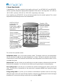
keyboard has the following functions and characteristics.
The unit has four operation modes:
Refrigeration mode.- this is the normal operation mode. The display shows the room temperature
and by pressing the set key the target temperature is shown. During the operation the electronic
control keeps a record of the maximum and minimum room temperature ever measured, which can be
consulted at any time.
Defrost mode.- the time on time your unit will switch to the defrost mode to eliminate the frost that has
formed on the evaporator. You can also force a defrost cycle by pressing the corresponding key.
Fast cooling mode.- If you like you can activate this operation mode during the start-up of the cold
room. The unit will run continuously for the preset time in parameter “CCt”, even beyond the target
temperature.
Energy saving mode.- If you like you can activate or deactivate this operation mode to save energy
during the night or when the room will stay closed for a long time. By activating this function the target
temperature is increased according to preset value in parameter “HES”.
Press for 3 seconds
to
activate the energy
saving function
Press to switch on
and off the room light
Press for 3 seconds
to force a defrost
cycle
Press to visualise
minimum temperature
record
Press to visualise the
target temperature,
which can be modified
by pressing
or
Press to visualise
maximum temperature
record
Press to turn on and
off the unit
DIGITAL DISPLAY
It shows the room
temperature.
By pressing the set key
it will show the target
temperature.
Operation LEDs

intarblock | intartop
3
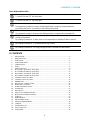
Basic keyboard functions.-
To switch ON and OFF the instrument.
To switch ON and OFF the room light.
To visualise maximum room temperature record
In programming mode it increases the displayed value or explores the parameter list.
by pressing the key for 3 seconds the fast cooling cycle starts.
To visualise minimum room temperature record
In programming mode it decreases the displayed value or explores the parameter list.
To display and modify target set point; in programming mode it selects a parameter or
confirm an operation.
By holding it pressed for 3s when max or min temperature is displayed it will be erased.
By holding it pressed for 3s a manual defrost cycle starts.
By holding it pressed for 3s Energy Saving function is activated or deactivated.
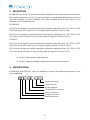
II. CONTENTS
1. DESCRIPTION ........................................................................................................................ 4
2. IDENTIFICATION .................................................................................................................... 4
3. OPERATION............................................................................................................................ 5
4. OPERATION LIMITS ............................................................................................................... 6
5. COMPOSITION ....................................................................................................................... 7
6. TESTS ..................................................................................................................................... 8
7. SAFETY DEVICES .................................................................................................................. 8
8. MCV SERIES TECHNICAL FEATURES ................................................................................ 9
9. BCV SERIES TECHNICAL FEATURES ............................................................................... 11
10. MCR SERIES TECHNICAL FEATURES .............................................................................. 12
11. BCR SERIES TECHNICAL FEATURES ............................................................................... 14
12. COOLING CAPACITY R404A ............................................................................................... 15
13. COOLING CAPACITY R134a ............................................................................................... 15
14. DIMENSIONS ........................................................................................................................ 18
15. ELECTRICAL CONNECTIONS ............................................................................................. 20
16. EMERGENCY SYSTEM........................................................................................................ 21
17. SOUND PRESSURE LEVEL ................................................................................................ 21
18. TRANSPORT......................................................................................................................... 21
19. DATA PLATE ......................................................................................................................... 22
20. SAFETY RECOMMENDATIONS .......................................................................................... 22
21. INSTALLATION AND MOUNTING........................................................................................ 23
22. START-UP ............................................................................................................................. 27
23. MAINTENANCE .................................................................................................................... 28
24. REFRIGERANT LOAD .......................................................................................................... 29
25. DISPOSAL MANAGEMENT .................................................................................................. 30
26. CONTROL ............................................................................................................................. 30
27. PARAMETER LIST ................................................................................................................ 33
28. FAULT ANALYSIS ................................................................................................................. 37
29. GUARANTEE ........................................................................................................................ 40

4
1. DESCRIPTION
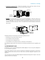
INTARBLOCK and INTARTOP units are monoblock refrigeration units in vertical and roof construction,
fullly tested and adjusted in Factory. They are assembled on a prelacquered galvanised steel shell and
have been designed for indoor installation, with easily removable panels to give access to fans,
refrigerant circuit, and electric board.
INTARBLOCK:
MCV Series are designed for positive temperature refrigeration applications from -5ºC (23ºF) to +10ºC
(50ºF) and consist of 12 models to cover a cooling capacity range from 0.5 kW to 3 kW
BCV Series are designed for positive temperature refrigeration applications from -15ºC (5ºF) to -25ºC
(13ºF) and consist of 9 models to cover a cooling capacity range from 0.4 kW to 2,5 kW
INTARTOP:
MCV Series are designed for positive temperature refrigeration applications from -5ºC (23ºF) to +10ºC
(50ºF) and consist of 10 models to cover a cooling capacity range from 0.5 kW to 2,5 Kw
BCR Series are designed for positive temperature refrigeration applications from -15ºC (5ºF) to -25ºC
(13ºF) and consist of 6 models to cover a cooling capacity range from 0.4 kW to 1,7 kW
- NF version – featuring axial condensation fan,
- CF version – featuring centrifugal condensation fan for ducted air extraction.
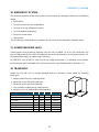
2. IDENTIFICATION
INTARBLOCK and INTARTOP series are identified according to the following nomenclature on the
product data plate.
M
C
V
-
N
F
-
1
024
Compressor capacity
Construction size
R-404A refrigerant
Vertical construction
Compact construction
(N) Standard (C) Centrifugal
Medium temperature

intarblock | intartop
5
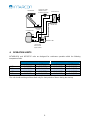
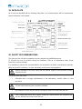
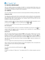
3. OPERATION
INTARBLOCK and INTARTOP are refrigeration machines operating under a vapour compression
cycle.
Refrigeration cycle
The refrigeration cycle uses a phase change refrigerant fluid in a closed circuit, with the following four
steps:
Expansion: refrigerant expansion takes place in the capillary tube between high and low pressure
sections. During the expansion, liquid refrigerant cools down to the evaporating temperature.
Evaporation: In the evaporator the refrigerant evaporates under constant temperature and pressure
absorbing heat from the cold room. Once the refrigerant vapour has been fully evaporated, it is slightly
overheated beyond the evaporation temperature.
Compression: The resultant refrigerant vapour is suctioned from the evaporator by the compressor
through the suction line. The compressor compresses the refrigerant vapour up to high pressure and
temperature.
Condensation: the hot high pressure gas is desuperheated and condensed, at a constant pressure
and temperature, in the el condenser by exhausting the latent evaporation to the outer ambient. Once
the refrigerant has been fully condensed, the liquid refrigerant is overcooled beyond the condensing
temperature.
High pressure liquid refrigerant is then driven to the capillary tube, and therefore closing the circuit.
Defrost cycle
Because of the evaporator temperature can be below 0ºC (32ºF), frost is likely to deposit on the
evaporator surface through the condensation of the water vapour contained in the air. To prevent the
air flow from being obstructed with the consequently loss of performance, the instrument switches
automatically to the defrost operation mode every given period of time.
During the defrost cycle, by opening the solenoid valve, part of the hot gas from the compressor
discharge is injected into the evaporator. The evaporator temperature is rapidly increased in order to
melt the frost on it while the inside fan is off.
The defrost water is collected in the drain tray and conducted to the drain bucket. This drain bucket
contains a hot gas coil to progressively evaporate the drain water to the outer ambient.

6
4. OPERATION LIMITS
INTARBLOCK and INTARTOP units are designed for continuous operation within the following
temperature limits:
Cold Room Temperature
Ambient Temperature
Max
Min
Max
Min
MCV +10 ºC (50ºF) -5 ºC (23ºF) +45 ºC (113ºF) +15 ºC (59ºF)
BCV -15 ºC (5ºF) -25 ºC (-13ºF) +45 ºC (113ºF) +15 ºC (59ºF)
MCR 10 ºC (50ºF) -5 ºC (23ºF) +45 ºC (113ºF) +15 ºC (59ºF)
BCR -15 ºC (5ºF) -25 ºC (-13ºF) +45 ºC (113ºF) +15 ºC (59ºF)
The unit should work beyond these limits only for short periods of time or during the start-up.
AP
BP
SOLENOID
VALVE
COMPRESSOR
DRAIN BUCKET
EVAPORATOR
CONDENSER
DRAIN TRAYFILTER
AP
BP
PRESSURE
REGULATOR
(only BCV/BCR)
CAPILLARY TUBE /
THERMOSTATIC
EXPANSION VALVE

intarblock | intartop
7
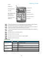
5. COMPOSITION
MCV / BCV units are built on a self-contained construction. The components are assembled on a steel
structure and covered with a prelacquered galvanised steel shell. It consists of:
Refrigerant circuit
§ Hermetic reciprocating compressor with internal protection, assembled on silentblocs
§ R404-A or R134a refrigerant load.
§ HP and LP pressure switches.
§ HP and LP load nipples.
§ Thermostatic expansion valve (capillary tube in medium temperature models with power lower
than 1,5 HP (R404A) and 1 HP (R134a).
§ Antiacid dehydrating filter.
§ Evaporation coil in copper tubes and aluminium fins with stainless steel drain tray.
§ Condensation coil in copper tubes and aluminium fins.
§ Solenoid valve for the hot gas bypass.
§ Water drain bucket including hot gas coil for the automatic evaporation of drain water.
Air circuits
N/I version:
§ Direct driven axial fans with single phase motor. Dynamically equilibrated blades with protection
grill.
C version:
§ Direct driven centrifugal fans with single phase motor. Dynamically equilibrated rotor.
Electric board
§ Circuit breaker protection
§ Electric control XW270K with the following elements and features:
- transformer 230 VAC / 12 VCC,
- microprocessor,
- alarm relay,
- compressor relay,
- defrost relay,
- evaporator fan relay,
- cold room light relay,
- condenser fan relay,
- door switch digital input
- H/LP pressure switch input
- inside temperature NTC probe
- outside temperature NTC probe
- defrost NTC probe
- RS485 connection,
- programming key connection,

8
- V820 keyboard.
§ Compressor permanent condenser in single phase units.
§ Compressor start relay and condenser in single phase units.
§ Ground connection for compressor and motorfans.
§ Cold room light.
§ Door microswitch connection.
§ Door microswitch (as an option).
§ Door heating cable (only for BCV and BCR models).
§ Crankcase heater (as an option).
§ Draining pipe heating cable (only for BCV y BCR models).
6. TESTS
Every INTARBLOCK and INTARTOP units have been previously checked and tested in factory
according to the following test protocol:
§ Helium leak-proof test. A leak-proof certificate is supplied upon request.
§ Refrigerant load.
§ Operation test for refrigeration and defrost modes under nominal operating conditions.
§ Safety devices checking
7. SAFETY DEVICES
INTARBLOCK and INTARBLOCK units feature the following safety devices:
§ HP and LP pressure limit switches to protect the unit against unusual pressure levels.
§ Thermal switches with automatic restart in compressor and fans to protect motor wirings from
overloads.
§ Circuit breaker protection
§ Common ground connection.

intarblock | intartop
9
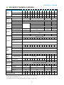
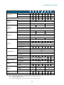
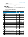
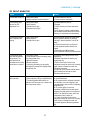
8. MCV SERIES TECHNICAL FEATURES
(1) Cooling capacity under cold room temperature of 0 ºC (32 ºF) and ambient temperature of 35 ºC (95 ºF).
(2) Total absorbed power by compressor and fans under nominal condition (axial version).
(3) As defined by RD138/2011. IF-01.
(4) Maximum absorbed current even beyond compressor operation limits (axial version).
MCV Series R404A 0008
0010
0012
1010
1012
1014
1016
1018
1024
2024
2026
2034
3034 3038
Cooling
capacity
Cooling capacity (1) (W) 610 728 808 799 930 1077
1184
1347
1468
1917
2149
2391
2690 3020
Absorbed power (2) (W) 470 570 640 649 672 804 869 1020
1175
1356
1474
1946
2070 1970
COP performance 1,30
1,28
1,27
1,23
1,38
1,34
1,36
1,32
1,25
1,41
1,46
1,23
1,30 1,53
Installed power (3) (kW) 0,53
0,73
0,86
0,75
0,82
0,98
1,10
1,38
1,68
1,68
1,89
2,63
2,63 2,35
Condenser
fan
NF version
Nominal air flow rate (m3/h) 375 575 1000 1350
Type Axial
Power (W) - r.p.m 85W @ 1300 2 x 85W @ 1300 2x70W@1300
Condenser
fan
CF version
Nominal air flow rate (m3/h)
-
575 1000 1350
Available static pressure (Pa) 45 90 120
Type Centrifugal
Power (W) 45 W 105 W 2 x 10⁵ W
Evaporator
fan
Nominal air flow rate (m3/h) 300 550 1050 1400
Range (m) 3 4
Type Axial
Power (W) - r.p.m 47W @ 2500 62W @ 2600 2 x 62W @ 2600 2x70W@2600
Compressor
Type Hermetic reciprocating
Swept volume (m3/h) 1,16
1,54
1,79
1,64
1,96
2,32
2,65
3,18
4,21
4,21
4,52
6,01
6,01 6,60
Nominal discharge pressure
(bar rel.) 20
Nominal suction pressure (bar
rel.) 3,40
Nominal power (CV) 1/3 3/8 1/2 3/8 1/2 1/2 5/8 3/4 1 1 1 1/4
1 1/2
1 1/2 1 3/4
High
pressure
switch
Type ACB
Brand Danfoss
Model 061F8175
Cut out (bar rel.) 28
Max.
absorbed
intensity
(A)(4)
230 V / I ph / 50 Hz 4,5 5,9 6,7 5,1 6,1 6,7 7,6 8,9 11,1
11,9
12,3
16,9
17,1 N/D
400 V / III ph / 50 Hz Not available 5,7 6,5 6,7 7,9
Starting-up
intensity (A)
230 V / I ph / 50 Hz 16,3
18,8
20,2
16,9
17,9
20,9
23,5
30,9
34,4
35,2
33,7
46,7
46,9 N/D
400 V / III ph / 50 Hz Not available 19,7
24,7
24,9 17,9
Refrigerant
Type R-404A / Group L1 / GWP-100: 3922
Load (kg) 0,50
0,50
0,56
0,70
0,70
0,70
0,78
0,76
0,76
1,00
0,98
1,10
1,66 1,50
Dimensions
Length (mm) 556 854 854 879
Wide (mm) 420 400 620 735
Height (mm) 683 880 920 920
Weight (kg) 35 37 38 59 60 60 69 70 70 88 89 89 117 114
Sound pressure level db(A) 30 30 30 31 31 32 34 35 35 36 38 40 39 40

10
(1) Cooling capacity under cold room temperature of 0 ºC (32 ºF) and ambient temperature of 35 ºC (95 ºF).
(2) Total absorbed power by compressor and fans under nominal condition (axial version).
(3) As defined by RD138/2011. IF-01.
(4) Maximum absorbed current even beyond compressor operation limits (axial version).
MCV series R134a 0010 0015
1015
1026
1033
2033
2053
3053
3074
3108
Cooling capacity
Cooling capacity (1) (W) 610 794 972
1281
1454
1790
2153
2489
3239
3927
Absorbed power (2) (W) 430 530 570
810
920
1090
1460
1510
1890
2480
COP performance 1,42 1,50 1,71
1,58
1,58
1,64
1,47
1,65
1,71
1,58
Installed power (3) (kW) 0,59 0,83 0,83
1,22
1,44
1,44
2,2
2,2
2,9 4,4
Condenser fan
NY version
Nominal air flow rate (m3/h) 375 575 950 1150
Type Axial
Power (W) - r.p.m 85 W @ 1300
2x 85 W @
1300 2x 70 W @ 1300
Condenser fan
CY version
Nominal air flow rate (m3/h) 375 575 950 1150
Available static pressure (Pa) 120
Type Centrifugal
Power (W) 180 W 220 W 2x 200W
2x 200W
Evaporator fan
Nominal air flow rate (m3/h) 300 500 950 1300
Range (m) 3 4
Type Axial
Power (W) - r.p.m 47W @ 2500 62W @ 2600
2x 62W @
2600 2x 70W @ 2600
Compressor
Type Hermetic reciprocating
Swept volume (m3/h) 2,08 3,18 3,18
4,51
5,69
5,69
9,26
9,26
12,92
18,74
Nominal discharge pressure (bar rel.) 10
Nominal suction pressure (bar rel.) 1
Nominal power (CV) 3/8 1/2 1/2
3/4
1 1
1 1/2
1 1/2
2 5
High pressure switch
Type ACB
Brand Danfoss
Model 061F6147
Cut out (bar rel.) 20
Max. absorbed
intensity (A)(4)
230 V / I ph / 50 Hz 5,9 6,9 7,0
10,7
10,9
11,17
13,77
14,19
19,74
-
400 V / III ph / 50 Hz Not available 18,5
Starting-up intensity
(A)
230 V / I ph / 50 Hz 13,2 20,7 20,7
27,0
30,0
30,0
46,0
46,0
55,0
-
400 V / III ph / 50 Hz Not available 65
Refrigerant
Type R-134a / Group A1 / GWP-100: 1430
Load (kg) 0,56 0,62 0,64
0,64
0,70
0,90
0,90
1,30
1,20
1,40
Dimensions
Length (mm) 306+250 340+514 340+514
365+514
Wide (mm) 420 400 620 735
Height (mm) 683 880 920 940
Weight (kg) 36 38 60 69 70 88 89 117
114 116
Sound pressure level db(A) 28 29 29 34 34 35 39 38 41 43

intarblock | intartop
11
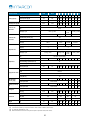
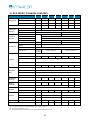
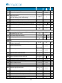
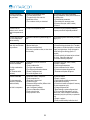
9. BCV SERIES TECHNICAL FEATURES
(1) Cooling capacity under cold room temperature of -20 ºC (-4 ºF) and ambient temperature of 35 ºC (95 ºF).
(2) Total absorbed power by compressor and fans under nominal condition (axial version).
(3) As defined by RD138/2011. IF-01.
(4) Maximum absorbed current even beyond compressor operation limits (axial version).
BCV Series R404A 0018 1018 1026 1034 2034 2054 2074 3074 3086 3096
Cooling capacity
Cooling capacity (1) (W) 479 489 720 866 1048 1349 1633 1930 2270 2460
Absorbed power (2) (W) 620 688 914 1136 1187 1685 2014 2380 2320 2640
COP performance 0,77 0,73 0,79 0,76 0,88 0,80 0,81 0,81 0,98 0,93
Installed power (3) (kW) 0,87 0,88 1,29 1,76 1,76 2,60 3,39 3,39 3,46 4,31
Condenser fan
NF version
Nominal air flow rate (m3/h) 375 575 1000 1350
Type Axial
Power (W) - r.p.m 85W @ 1300 2 x 85W @ 1300 2 x 70W @ 1300
Condenser fan
CF version
Nominal air flow rate (m3/h)
-
575 1000 1350
Available static pressure (Pa) 45 90 120
Type Centrifugal
Power (W) 45 W 105 W 2 x 10⁵ W
Evaporator fan
Nominal air flow rate (m3/h) 300 550 1050 1400
Range (m) 3 4
Type Axial
Power (W) - r.p.m 47W
@
2500 62W @ 2600 2 x 62W @ 2600 2 x 70W @ 2600
Compressor
Type Hermetic reciprocating
Swept volume (m3/h) 3,18 3,18 4,57 6,01 6,01 9,25 12,91 12,91 11,80 16,70
Nominal discharge pressure (bar
rel.) 20
Nominal suction pressure (bar rel.) 1,30
Nominal power (CV) 5/8 5/8 3/4 1 1/4 1 1/4 1 3/4 2 1/2 2 1/2 3 3 1/2
High pressure
switch
Type ACB
Brand Danfoss
Model 061F8175
Cut out (bar rel.) 28
Max. absorbed
intensity (A)(4)
230 V / I ph / 50 Hz 4,8 7,2 8,4 10,9 11,7 17,7 25,7 25,9 No disponible
400 V / III ph / 50 Hz Not available 6,5 7,2 7,4 10,3 12,0
Starting-up
intensity (A)
230 V / I ph / 50 Hz 21,9 21,9 29,9 40,9 41,7 69,7 82,7 82,9 No disponible
400 V / III ph / 50 Hz Not available 24,7 29,7 29,9 26,9 33,9
Refrigerant
Type R-404A / Group L1 / GWP-100: 3922
Load (kg) 0,60 0,70 0,70 0,60 1,15 1,05 1,10 1,50 1,50 1,20
Dimensions
Length (mm) 556 854 854 879
Wide (mm) 420 400 620 735
Height (mm) 683 880 920 920
Weight (kg) 38 59 60 60 89 102 102 131 117 129
Sound pressure level db(A) 33 38 38 40 41 42 43 43 40 50

12
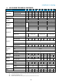
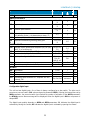
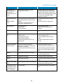
10. MCR SERIES TECHNICAL FEATURES
(1) Cooling capacity under cold room temperature of 0 ºC (32 ºF) and ambient temperature of 35 ºC (95 ºF).
(2) Total absorbed power by compressor and fans under nominal condition (axial version).
(3) As defined by RD138/2011. IF-01.
(4) Maximum absorbed current even beyond compressor operation limits (axial version).
MCR Series R404A 0008
0010
0012
1010
1012
1014
1016
1018
1024
2024
2026
2034
Cooling
capacity
Cooling capacity (1) (W) 612 738 838 799 930 1087
1194
1378
1478
2020
2223
2527
Absorbed power (2) (W) 470 580 650 652 672 811 880 1038
1201
1319
1425
1903
COP performance 1,30 1,27 1,29 1,23 1,38 1,34 1,36 1,33 1,23 1,53 1,56 1,33
Installed power (3) (kW) 0,53 0,73 0,86 0,75 0,82 0,98 1,10 1,38 1,68 1,68 1,89 2,63
Condenser
fan
NF version
Nominal air flow rate (m3/h) 375 575 1150
Type Axial
Power (W) - r.p.m 85 W @ 1300 rpm 120W @ 1300 rpm
Condenser
fan
CF version
Nominal air flow rate (m3/h)
-
575 1150
Available static pressure (Pa) 45
Type Centrifugal
Power (W) 45 W @ 1300 rpm 105 W @ 1300 rpm
Evaporator
fan
Nominal air flow rate (m3/h) 300 600 1150
Range (m) 3 4
Type Axial
Power (W) - r.p.m 47@ 2500 rpm 62W @ 2600 rpm 2x 62W @ 2600
rpm
Compressor
Type Hermetic reciprocating
Swept volume (m3/h) 1,16 1,54 1,79 1,64 1,96 2,32 2,65 3,18 4,21 4,21 4,52 6,01
Nominal discharge pressure (bar
rel.) 20
Nominal suction pressure (bar
rel.) 3,40
Nominal power (CV) 1/3 3/8 1/2 3/8 1/2 1/2 5/8 3/4 1 1 1 1/4
1 1/2
High pressure
switch
Type ACB
Brand Danfoss
Model 061F8175
Cut out (bar rel.) 28
Max.
Absorbed
intensity(4)(A)
230 V / I ph / 50 Hz 4,5 5,9 6,7 5,1 6,1 6,7 7,6 8,9 11,1 11,6 12,0 16,6
400 V / III ph /50 Hz Not available 5,4 6,2
Starting up
intensity (A)
230 V / I ph / 50 Hz 16,3 18,8 20,2 16,9 17,9 20,9 23,5 30,9 34,4 34,9 33,4 46,4
400 V / III ph /50 Hz Not available 19,4 24,4
Refrigerant
Type R-404A / Group L1 / GWP-100: 3922
Load (kg) 0,50 0,50 0,50 0,80 0,70 0,80 0,83 0,76 0,86 1,10 1,05 1,10
Dimensions
Length (mm) 790 850 850
Wide (mm) 600 665 835
Height (mm) 480 385+189 468+189
Weight (kg) 62 64 65 73 73 73 82 83 83 98 99 99
Sound pressure level db(A) 30 30 30 32 32 32 34 35 35 36 38 40

intarblock | intartop
13
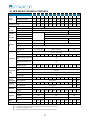
(1) Cooling capacity under cold room temperature of 0 ºC (32 ºF) and ambient temperature of 35 ºC (95 ºF).
(2) Total absorbed power by compressor and fans under nominal condition (axial version).
(3) As defined by RD138/2011. IF-01.
(4) Maximum absorbed current even beyond compressor operation limits (axial version).
MRC series R134a 0010 0015 1015
1026 1033 2033 2053
2074
Cooling capacity
Cooling capacity (1) (W) 605 788 999 1265 1502 1911 2352
2940
Absorbed power (2) (W) 430 530 580 930 1050 1210 1670
1830
COP performance 1,41 1,48 1,72 1,36 1,43 1,58 1,41 1,61
Installed power (3) (kW) 0,83 0,83 1,22 1,44 1,44 2,2 2,9
Condenser fan
NF version
Nominal air flow rate (m3/h) 375 575 1000
Type Axial
Power (W) - r.p.m 85 W @ 1300 120 W @ 1300
Condenser fan
CF version
Nominal air flow rate (m3/h) 375 575 1000
Available static pressure (Pa) 120
Type Centrifugal
Power (W) 180 W 220 W 2x 200 W
Evaporator fan
Nominal air flow rate (m3/h) 300 600 1150
Range (m) 4
Type Axial
Power (W) - r.p.m 47W @ 2500
62W @ 2600 2x 62W @ 2600
Compressor
Type Hermetic reciprocating
Swept volume (m3/h) 2,08 3,18 3,18 4,51 5,69 5,69 9,26 12,92
Nominal discharge pressure (bar rel.) 10
Nominal suction pressure (bar rel.) 1
Nominal power (CV) 3/8 1/2 1/2 3/4 1 1 1 1/2
2
High pressure switch
Type ACB
Brand Danfoss
Model 061F6147
Cut out (bar rel.) 20
Max. Absorbed intensity(4)(A)
230 V / I ph / 50 Hz 5,94 6,94 7,00 10,70
10,90
11,17
13,7 11,77
400 V / III ph /50 Hz Not available
Starting up intensity (A)
230 V / I ph / 50 Hz 16 22 22 29 30 30 46 55
400 V / III ph /50 Hz Not available
Refrigerant
Type R-134a / Grupo A1 / PCA-100: 1430
Load (kg) 0,46 0,50 0,70 0,70 0,60 1,00 1,00 1,10
Dimensions
Length (mm) 790 850 850
Wide (mm) 600 665 835
Height (mm) 330+100 385+135 469+135
Weight (kg) 62 65 73 82 83 98 99 110
Sound pressure level db(A) 30 30 28 34 34 35 39 41

14
11. BCR SERIES TECHNICAL FEATURES
(1) Cooling capacity under cold room temperature of 0 ºC (32 ºF) and ambient temperature of 35 ºC (95 ºF).
(2) Total absorbed power by compressor and fans under nominal conditions.
(3) As defined by RD138/2011. IF-01.
(4) Maximum absorbed current even beyond compressor operation limits (axial version)
BCR Series R404A 0008 1018 1026 1034 2034 2054 2074
Cooling capacity
Cooling capacity (1) (W) 515 502 734 876 1102 1443 1689
Absorbed power (2) (W) 630 671 928 1160 1297 1830 2147
COP performance 0,81 0,75 0,79 0,76 0,85 0,79 0,79
Installed power (3) (kW) 0,87 0,88 1,29 1,76 1,76 2,60 3,39
Condenser fan
NF version
Nominal air flow rate (m3/h) 375 575 1150
Type Axial
Power (W) - r.p.m 85 W @ 1300 rpm 120 W @ 1300 rpm
Condenser fan
CF version
Nominal air flow rate (m3/h)
-
575 1150
Available static pressure (Pa) 45
Type Centrifugal
Power (W) 45 W @ 1300 rpm 105 W @ 1300 rpm
Evaporator fan
Nominal air flow rate (m3/h) 300 600 1150
Range (m) 3 4
Type Axial
Power (W) - r.p.m 47 W @
2500rpm 62 W @ 2600 rpm 2 x 62 W @ 2600 rpm
Compressor
Type Hermetic reciprocating
Swept volume (m3/h) 3,18 3,18 4,57 6,01 6,01 9,25 12,91
Nominal discharge pressure (bar
rel.) 20
Nominal suction pressure (bar rel.) 1,30
Nominal power (CV) 5/8 5/8 3/4 1 1/4 1 1/4 1 3/4 2 1/2
High pressure
switch
Type ACB
Brand Danfoss
Model 061F8175
Cut out (bar rel.) 28
Max. absorbed
intensity (A)
230 V / I ph / 50 Hz 4,8 7,2 8,4 10,9 11,4 17,4 25,4
400 V / III ph / 50 Hz Not available 6,21 6,91
Starting-up
intensity (A)
230 V / I ph / 50 Hz 21,9 21,9 29,9 40,9 41,4 69,4 82,4
400 V / III ph /50 Hz Not available 24,4 29,4
Refrigerant
Type R-404A / Grupo L1 / PCA-100: 3260
Load (kg) 0,64 0,75 0,75 0,80 1,20 1,00 1,10
Dimensions
Length (mm) 790 850 850
Wide (mm) 600 665 835
Height (mm) 480 385+189 468+189
Weight (kg) 65 83 84 84 135 145 145
Sound pressure level db(A) 33 38 38 40 41 42 43

intarblock | intartop
15
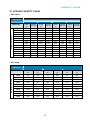
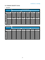
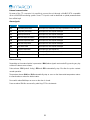
12. COOLING CAPACITY R-404A
§ MCV series
Capacity (W) Cold room temperature
-5 ºC 0 ºC +5 ºC +10 ºC
MCV series
Cooling
capacity
(W)
Absorbed
power (W)
Cooling
capacity
(W)
Absorbed
power (W)
Cooling
capacity
(W)
Absorbed
power (W)
Cooling
capacity
(W)
Absorbed
power (W)
Ambient Temp: 35 ºC
0008 502 446 610 470 738 506 860 534
0010 604 533 728 570 871 624 1012 666
0012 568 619 808 676 961 706 1118 759
1010 630 613 801 649 966 683 1157 722
1012 767 631 930 672 1118 714 1317 763
1014 893 756 1077 804 1270 858 1485 920
1016 985 800 1184 869 1386 939 1615 1018
1018 1138 940 1347 1020 1570 1104 1806 1200
1024 1207 1049 1468 1175 1739 1305 2039 1450
2024 1554 1245 1917 1356 2296 1464 2726 1579
2026 1795 1368 2149 1474 2526 1584 2945 1707
2034 1996 1805 2391 1946 2801 2102 3247 2282
3034 2230 1925 2690 2070 3200 2220 3730 2390
3038 2500 1830 3020 1970 3580 2110 4220 2270
§ BCV series
Capacity (W) Cold room temperature
-25 ºC -20 ºC -15 ºC
MCV series
Cooling capacity
(W)
Absorbed power
(W)
Cooling capacity
(W)
Absorbed power
(W)
Cooling capacity
(W)
Absorbed power
(W)
Ambient Temp: 35 ºC
0018 379 565 479 620 591 694
1018 383 611 489 668 655 747
1026 548 802 720 914 877 1015
1034 668 986 866 1136 1023 1254
2034 793 1196 1048 1334 1297 1463
2054 963 1592 1349 1832 1655 2026
2074 1338 1931 1633 2161 1963 2405
3074 1430 2070 1930 2380 2320 2660
3086 1630 2000 2270 2320 2810 2560
3096 1890 2280 2460 2640 3040 2970

16
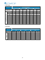
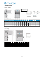
§ MCR Series
Capacity (W) Cold room temperature
-5 ºC 0 ºC +5 ºC +10 ºC
MCR Series
Cooling
capacity
(W)
Absorbed
power (W)
Cooling
capacity
(W)
Absorbed
power (W)
C
ooling
capacity
(W)
Absorbed
power (W)
Cooling
capacity
(W)
Absorbed
power (W)
Ambient Temp.: 35 ºC
0008 508 455 612 470 720 521 851 547
0010 621 537 738 580 901 629 1055 681
0012 701 598 838 650 1012 712 1163 766
1010 630 617 801 652 966 682 1157 727
1012 767 637 930 672 1118 717 1317 772
1014 916 761 1087 811 1275 867 1479 929
1016 1005 811 1194 880 1402 953 1628 1031
1018 1161 957 1378 1038 1579 1118 1828 1211
1024 1217 1070 1478 1201 1782 1335 2062 1462
2024 1625 1201 2020 1319 2402 1409 2888 1527
2026 1849 1324 2223 1425 2646 1531 3077 1648
2034 2080 1768 2527 1903 2987 2059 3380 2190
§ BCR Series
Capacity (W) Cold room temperature
-25 ºC -20 ºC -15 ºC
BCR Series Cooling
capacity (W)
Absorbed power
(W)
Cooling capacity
(W)
Absorbed power
(W)
Cooling capacity
(W)
Absorbed power
(W)
Ambient Temp:
35 ºC
0018 405 570 515 630 618 700
1018 407 618 502 671 664 752
1026 565 813 734 928 908 1039
1034 699 1015 876 1160 1051 1287
2034 840 1157 1102 1297 1366 1433
2054 1116 1617 1443 1830 1733 2005
2074 1425 1932 1689 2147 2088 2416

intarblock | intartop
17
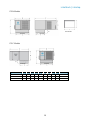
13. COOLING CAPACITY R-134a
· Serie MCV
Capacity (W) Cold room temperature
0 ºC +5 ºC +10 ºC
MCV Series Cooling
capacity (W)
Absorbed
power (W)
Cooling
capacity (W)
Absorbed
power (W)
Cooling
capacity (W)
Absorbed
power (W)
Ambient Temp: 35 ºC
0010 610 437 758 477 907 508
0015 794 532 961 587 1139 642
1015 972 572 1199 622 1453 672
1026 1281 812 1565 892 1859 972
1033 1454 922 1743 1012 2037 1112
2033 1790 1099 2163 1184 2573 1274
2053 2153 1464 2609 1634 3103 1809
3053 2489 1515 3103 1700 3743 1870
3074 3239 1895 3938 2145 4667 2400
3108 3927 2485 4725 2790 5539 3145
· Serie MCR
Capacity (W) Cold room temperature
0 ºC +5 ºC +10 ºC
MCR Series Cooling
capacity (W)
Absorbed
power (W)
Cooling
capacity (W)
Absorbed
power (W)
Cooling
capacity (W)
Absorbed
power (W)
Ambient Temp: 35 ºC
0010 605 432 751 471 902 505
0015 788 530 956 577 1134 640
1015 999 580 1231 673 1490 691
1026 1265 930 1549 884 1853 970
1033 1502 1050 1817 1067 2153 1176
2033 1911 1210 2363 1210 2846 1347
2053 2352 1670 2882 1689 3455 1855
2074 2940 1830 3560 1945 4211 2147

18
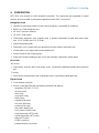
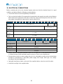
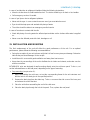
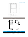
14. DIMENSIONS
CV-N-C Models
CV-I Models
Dimensions (mm) A B C D E F G H
1
series
340 330 1060 400 514 115 380 335
2
series
340 330 1100 620 514 115 600 335
3
series
365 470 1100 735 514 115 710 475
Dimensions (mm) A B C D E F G H I J K L M Exhaust
duct
0 series 306 510 683 420 250 50 405 515 n/a Ø 150
1 series 340 330 880 400 514 122 380 335 75 41 295 13 233 Ø 150
2 series 340 330 920 620 514 122 600 335 75 36 523 13 233 Ø 150
3 series 365 470 920 735 514 122 710 475 75 41 611 22 356 2x Ø 150
PLUG
-
IN FRAME
DROP FRAME
Centrifugal Box
only in 0 series

intarblock | intartop
19
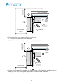
CR-N Models
CR-C Models
Dimensions (mm) A B C D E F G H I Exhaust duct
0 series 480 600 430 330 790 375 100 435 380 Ø 150
1 series 574 665 582 385 850 379 135 588 385 Ø 150
2 series 677 835 756 469 850 379 135 762 385 Ø 150
ROOF FRAME

20
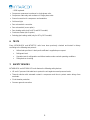
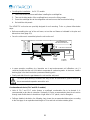
15. ELECTRICAL CONNECTIONS
Before connecting the unit to the electrical supply, make sure that the electrical board is in good
conditions and please follow the following recommendations:
§ Consult the electrical schema supplied by manufacturer.
§ Only use electrical cables of the appropriate characteristics and capacity according to the following
table. Notice that single phase units have a three-wire supply and three phase units have a five-
wire supply, being always the ground wire in green-yellow colour.
MCV - MCR 0008 0010 0012 1010 1012 1014 1016 1018 1024 2024 2026 2034 3034 3038
Power supply
220-I-50 2 x 1,5 mm² + T
2 x 2,5 mm² +
T
Power supply
400-III-50
4 x 1,5 mm² + T
Cold room light 2 x 1 mm² + T
Door
microswitch 2 x 1 mm²
Remote
controller 2 x 1 mm²
BCV - BCR 0018 1018 1026 1034 2034 2054 2074 3074 3086 3096
Power supply 220-I-50 2 x 1,5 mm² + T 2 x 2,5 mm² +
T 2 x 4 mm² +
T
Power supply 400-III-50 4 x 1,5 mm² + T
Cold room light 2 x 1 mm² + T
Door microswitch 2 x 1 mm²
Remote controller 2 x 1 mm²
Power supply 220-I-50 2 x 1 mm²
§ Always install the appropriate protection device on the supply line. In case that more than one unit
is installed, always provide separate protection devices for each of the installed units.
§ Electrical wires section in power supply wiring is to be calculated according to the electrical data
provided by manufacturer in data plate, power supply wires length, wires type, etc.; always
according to electrical regalement.
§ Optionally install a door switch on the end of the supplied cable or close the end of the cable.
§ Install the room light in the supplied cable.
Page is loading ...
Page is loading ...
Page is loading ...
Page is loading ...
Page is loading ...
Page is loading ...
Page is loading ...
Page is loading ...
Page is loading ...
Page is loading ...
Page is loading ...
Page is loading ...
Page is loading ...
Page is loading ...
Page is loading ...
Page is loading ...
Page is loading ...
Page is loading ...
Page is loading ...
Page is loading ...
Page is loading ...
Page is loading ...
Page is loading ...
Page is loading ...
-
 1
1
-
 2
2
-
 3
3
-
 4
4
-
 5
5
-
 6
6
-
 7
7
-
 8
8
-
 9
9
-
 10
10
-
 11
11
-
 12
12
-
 13
13
-
 14
14
-
 15
15
-
 16
16
-
 17
17
-
 18
18
-
 19
19
-
 20
20
-
 21
21
-
 22
22
-
 23
23
-
 24
24
-
 25
25
-
 26
26
-
 27
27
-
 28
28
-
 29
29
-
 30
30
-
 31
31
-
 32
32
-
 33
33
-
 34
34
-
 35
35
-
 36
36
-
 37
37
-
 38
38
-
 39
39
-
 40
40
-
 41
41
-
 42
42
-
 43
43
-
 44
44


INTARCON BCR-N User & Installation Manual
- Type
- User & Installation Manual
Ask a question and I''ll find the answer in the document
Finding information in a document is now easier with AI
Other documents
-
GGM Gastro KC1400ND Owner's manual
-
-
Hansgrohe 15763003 User manual
-
Emerson XMC25D COPELAND LARGE OUTDOOR REFRIGERATION UNITS Installation guide
-
AGI Axial Flow Aeration Fan Owner's manual
-
Roca BCH-30 Datasheet
-
Lennox EcoLean EAC0431S Installation Operating & Maintenance Manual
-
Reznor RTU User manual
-
CIAT ASW-100 Installation, Operation, Commissioning, Maintenance
-
Sime SHP M PLUS 021 Installation guide