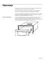
Thermador WD30ES Installation guide
- Category
- Warming drawers
- Type
- Installation guide
This manual is also suitable for
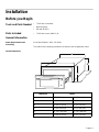
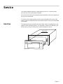
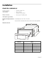
Thermador WD30ES Warming Drawer is the perfect complement to your kitchen. With three heat settings (low, medium, and high) and a temperature range of 90-160°F (32-71°C), you can keep food warm and at the right temperature until you're ready to serve. The spacious drawer can hold up to 24 dinner plates or 150 tortillas, making it perfect for large gatherings or everyday use. The stainless steel construction is durable and easy to clean, and the digital display makes it easy to monitor the temperature.
Thermador WD30ES Warming Drawer is the perfect complement to your kitchen. With three heat settings (low, medium, and high) and a temperature range of 90-160°F (32-71°C), you can keep food warm and at the right temperature until you're ready to serve. The spacious drawer can hold up to 24 dinner plates or 150 tortillas, making it perfect for large gatherings or everyday use. The stainless steel construction is durable and easy to clean, and the digital display makes it easy to monitor the temperature.


-
 1
1
-
 2
2
-
 3
3
-
 4
4
-
 5
5
-
 6
6
-
 7
7
-
 8
8
-
 9
9
-
 10
10
-
 11
11
-
 12
12
-
 13
13
-
 14
14
-
 15
15
-
 16
16
-
 17
17
-
 18
18
-
 19
19
-
 20
20
-
 21
21
-
 22
22
-
 23
23
-
 24
24
-
 25
25
-
 26
26
-
 27
27
-
 28
28


Thermador WD30ES Installation guide
- Category
- Warming drawers
- Type
- Installation guide
- This manual is also suitable for
Thermador WD30ES Warming Drawer is the perfect complement to your kitchen. With three heat settings (low, medium, and high) and a temperature range of 90-160°F (32-71°C), you can keep food warm and at the right temperature until you're ready to serve. The spacious drawer can hold up to 24 dinner plates or 150 tortillas, making it perfect for large gatherings or everyday use. The stainless steel construction is durable and easy to clean, and the digital display makes it easy to monitor the temperature.
Ask a question and I''ll find the answer in the document
Finding information in a document is now easier with AI
in other languages
- français: Thermador WD30ES Guide d'installation
- español: Thermador WD30ES Guía de instalación
Related papers
-
Thermador WD30 User manual
-
-
-
Thermador MED302 User manual
-
-
-
-
-
Thermador MED302RWS Installation guide
-
Thermador MED302LWS Installation guide
Other documents
-
Bosch HWD30 Installation guide
-
Bosch HDI7052C/09 Installation guide
-
Bosch HDI7132U/05 User manual
-
-
Bosch HEI7052U/08 Installation guide
-
Siemens HF35M630/01 User manual
-
Bosch HBL33 User manual
-
Bosch Food Warmer HWD27 User manual
-
Bosch HDI8054U/07 Installation guide
-
Bosch HII8056C/03 Installation guide