Page is loading ...

Vincent
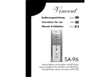
SV-122
Digitaler RDS AV Mehrkanal-Receiver
Digital RDS AV Surround Receiver
Ampli-Tuner 5.1 AV RDS
Bedienungsanleitung deutsch
Instructions for use english
Manuel d‘ utilisation français

2
Vincent
Sehr geehrter Kunde,
wir danken Ihnen für das Vertrauen, welches Sie uns durch die Entscheidung für dieses hochwertige Audio-
Produkt, das Ihrem hohen Anspruch an Klang- und Verarbeitungsqualität gerecht wird, entgegenbringen.
Auch wenn Sie verständlicherweise sofort beginnen wollen, das Gerät zu verwenden, lesen Sie bitte vor
dem Aufstellen und Anschließen dieses Handbuch sorgfältig durch. Es wird Ihnen bei der Bedienung und
der optimalen Nutzung des Gerätes in Ihrem System helfen, selbst wenn dieses durch Ihren Fachhändler
installiert wurde.
Bitte beachten Sie vor allem die Sicherheitshinweise, auch wenn einige davon offensichtlich erscheinen
mögen.
Um Ihnen verwendete Fachbegriffe zu erläutern, ist ein kleines Lexikon im Anhang enthalten. Bei eventuel-
len Fragen steht Ihnen Ihr Fachhändler gern zur Verfügung, er ist auch Ihr Ansprechpartner im Fall der
Garantie-Inanspruchnahme oder für Reparaturen nach dem Gewährleistungszeitraum. Er ist in jedem Fall
interessiert daran, dass Sie ihm Ihre Erfahrungen mit Vincent-Produkten mitteilen.
Viel Freude mit unserem/Ihrem Produkt wünscht Ihnen Ihr Vincent-Team
Dear Customer,
we thank you for the confidence you prove in purchasing our product. It will match your high demands
towards sound and manufacturing quality.
Though it is understandable that you want to plug and play this product instantaneously, we encourage
you to read this manual carefully before installation. It will help you in handling and operating this machi-
ne in your system and obtaining the best possible performance, even if it was installed by your dealer.
Please follow the security precautions, though some instructions may seem obvious.
In the appendix to this manual you will find a glossary explaining some established technical terms. If
there are open questions your audio specialist dealer will help you. He also represents your contact per-
son in case of needed warranty service or repairs after the warranty period and is interested to hear from
your experiences with Vincent products.
We wish you plenty of joy with your / our product, your Vincent-Team
Cher client,
nous vous remercions de la confiance que vous nous témoignez en achetant ce produit de haute qualité.
Il répondra à vos attentes élevées en termes de qualité sonore et de fabrication.
Même si l'on peut comprendre que vous ayez envie d'utiliser immédiatement cet appareil, nous vous pri-
ons de lire soigneusement ce manuel avant son installation et son branchement. Il vous aidera à manier et
utiliser l'appareil de manière optimale dans votre système, même si celui-ci a été installé par votre reven-
deur.
Veuillez respecter les consignes de sécurité, même si certaines peuvent vous paraître évidentes.
Vous trouverez à la fin de ce manuel un petit glossaire qui vous explique les termes techniques utilisés.
Votre revendeur est à votre disposition pour répondre à vos questions. Il est aussi votre interlocuteur en cas
de recours à la garantie ou pour les réparations après la période de garantie. Dans tous les cas, vos expé-
riences avec les produits Vincent l'intéressent, n'hésitez pas à lui en faire part.
Nous vous souhaitons beaucoup de plaisir avec notre / votre produit. Votre équipe Vincent

Vincent
3
INHALTSVERZEICHNIS/CONTENTS/SOMMAIRE
Sicherheitshinweise 4
Weitere Hinweise 5
Lieferumfang 6
Beschreibung des Gerätes 6
Fernbedienung 9
Installation 12
Lautsprecher-Einstellungen 20
Bedienung des Gerätes 25
Weitere Tipps 31
Fehlersuche 32
Lexikon/Wissenswertes 33
Technische Daten 35
Security precautions 36
User Information 37
Scope of delivery 38
Description of the device 38
Remote control 41
Installation 44
Speaker Settings 52
Operating the receiver 56
Tips 61
Troubleshooting 62
Glossary 63
Technical Specifications 65
Consignes de sécurité 66
Informations complémentaires 67
Contenu de la livraison 68
Description de l'appareil 68
Télécommande 71
Installation 74
Configuration des haut-parleurs 82
Commandes de l'appareil 86
Conseils 91
Dépannage 92
Glossaire 93
Caractéristiques techniques 95
english
français
deutsch

36
Vincent
SECURITY PRECAUTIONS
This product has been designed and manufactured under strict
quality and safety standards to meet all effective international
security regulations. However, you should consider the following
security precautions to avoid unnecessary harms:
Cleaning
Unplug the power cord from the wall outlet before
cleaning the surface of the appliance. Use a damp
cloth. Do not use aerosol cleaners, solvents, thin-
Maintenance / Changes
All devices connected to the wall outlet power supply
may be dangerous to the user when used improperly.
Do not attempt to service this product yourself. There
are no servicable parts inside. Refer servicing to qua-
lified personal only. This product or parts of this pro-
duct must not be changed or reconstructed as this will
void the warranty, as is the case for changes at the
serial number. This product should be operated only
from a power source providing 230Volts/50Hz AC.
The power outlet must be compatible to the safety plug.
Use this audio component only indoors. After a failu-
re that tripped the fuse contact your audio specialist
dealer or a service technician to replace this part.
Mains supply cord / Power Connection
Always pull the plug and never at the cable when
separating the power cord from the power line.
Make sure the power cable is not being squeezed,
bent unnaturally or cut by sharp edges. Do not touch
the cable with wet hands. Use the provided power
cable or other ones offered by Vincent.
Humidity/Heat and Vibrations
The contact with moisture, liquids, rain or steam is a
danger for all electrically powered devices and their
users. Dangerous high voltages are present inside
the enclosure. To reduce the risk of fire or electric
shock, exposition of the appliance to those should be
avoided. If that happened accidentally, the applian-
ce must be separated from the power outlet and
checked by a service technician. Never allow ob-
jects of any kind or liquids to get inside this product,
through openings, as they may touch dangerous vol-
tage points or short-out parts which could result in a
fire or electric shock. Do not use the appliance near
water. This product should be situated away from all
heat sources such as radiators, heat registers, stoves
or other products that produce heat. Do not expose
it to direct sunlight for an extended period. Do not
expose the device to heavy vibrations.
Switch off
Always switch off the appliance before connecting or
separating cable connections to other devices or loud-
speakers, connecting or separating the power supply
connection, leaving the device unused for an extended
period or cleaning of the surface. After switching off
power amplifiers, integrated amplifiers or receivers wait
for about 1 minute before changing cable connections.
Heat generation
All amplifiers generate heat. A minimum distance of
50 mm around the sides and top of the device is re-
commended to provide adequate ventilation. Do not
use the appliance in a closed cabinet or book case.
Volume
The maximum bearable loudness mostly appears far
beneath the maximum volume setting of the amplifier.
So be careful with this setting to avoid damage to
your hearing. To prevent unwanted high sound level
always reduce the volume setting before changing to
another input channel.
ON
OFF
CAUTION! RISK OF ELECTRIC SHOCK!
Do not remove cover (or back). No user-serviceable parts inside refer servicing to
qualified service personel.

Vincent
37
SECURITY PRECAUTIONS
Placing the components of
your audio system
The setup and way of placement of your audio
system will affect its sound quality. Therefore, place
the equipment only on top of an adequate and sta-
ble base. To achieve the maximum of the sound qua-
lity potential of your system we recommend to place
your electronic audio equipment on Vincent Racks
and to not pile up the components.
Electronic waste regulations
This device is covered by the European directive
2002/96/EC. This is displayed by the crossed-
out wheeled bin symbol on the back side of the
housing.
The meaning for you is:
All electric and electronic devices that are out of use
must be disposed of separately from the household
waste and can be deposited free of charge in desi-
gnated local and communal collection facilities ap-
pointed by the government or the local authorities.
In doing so you help prevent potential negative con-
sequences for the environment and human health.
It will motivate manufacturers to produce recyclable
and longlife products. You can obtain further infor-
mation at your city office, the waste disposal service
or the shop where you purchased the product.
CE - sign and regulations
This appliance is in accordance with all valid EU-
regulations necessary for receiving the right to dis-
play the CE-Sign. It is in conformity with the requi-
rements to electric and electronic devices (EMC
regulations, safety regulations and guidelines for
low voltage devices).
ners, inflamable chemicals, polish or other pro-
ducts that leave stains.
Battery Cells
Please read about the handling of batteries in the
chapter „Remote control“.
Copyrights
© November 2006, all rights reserved.
This document has been created by Andreas Böer.
It is a product of the Sintron Vertriebs GmbH, 76473
Iffezheim, Germany and must not (in parts or com-
plete) be copied or distributed without their permis-
sion in written form.
Vincent is a registered trademark owned by Sintron
Vertriebs GmbH, 76473 Iffezheim, Germany.
“Dolby”, “Prologic”, and the double-D symbol are
trademarks of Dolby Laboratories, Inc.
Disclaimer
Vincent is permanently improving and developing its
products. This means that designs, componentry or fea-
tures are subject to changes without notice. Manufac-
turer and owner of the trademark have no obligation
to announce technical changes to the appliance as far
as dedicated to the technical progress.
All contents of this manual are of informational charac-
ter and may be altered at any time without prior notice.
No obligations or responsibilities for the owner of the
trademark Vincent arise from these informations. He will
not take responsibility for the correctness of the given
information.
Explanation of the graphic symbols
The lightning flash is intended to alert you to the presence
of uninsulated “dangerous voltage” within the product's
enclosure that may be of sufficient magnitude to
constitute a risk of electric shock to persons.
The exclamation point is intended to alert the user to
important operating and maintenance (servicing) in-
structions in the literature accompanying the
product.
This symbol marks useful hints and information.
USER INFORMATION

38
Vincent
SCOPE OF DELIVERY
DESCRIPTION OF THE DEVICE
Please check the contents of the package, it should contain the
receiver SV-122 and the following:
• 1 remote control VRC-12
• 2 batteries of the type AAA (LR3)
• 1 power cable
• 1 AM loop antenna
• 1 FM antenna wire
• this handbook
Home theater systems are supposed to make origi-
nal movies an authentical and sensational experi-
ence. A unit of purely Vincent AV components can
master this challenge in excellence. Accurate elec-
tronics circuit design, up-to-date decoding techno-
logy, approved solid mechanical construction and
large reserves in the electrical power circuit make
the reproduction of explosive film scenes as well
as quiet and sensitive passages as close to reality
as possible. Additionally, benchmarks in cost-per-
formance ratio are set.
The SV-122 is a compact, user friendly multi chan-
nel receiver with extraordinary dynamics and the
renowned musicality of Vincent audio products.
Never compromising in Stereo as well as in Multi
Channel Mode. It is the ideal partner for speakers
and DVD players made by Vincent.
The device offers:
• decoding technology for Dolby Prologic II, PCM-Stereo and the digital surround formats
• an RDS Tuner with 30 presets for each frequency band (AM or FM)
• a clearly arranged, high-contrast, dimmable display
•
more than enough power for most speaker types: 5x60 Watts RMS at 4, active or passive subwoofer possible
• all functions remote controllable
• a multi function knob at the front panel for convenient control of most functions
• audio input connectors for up to 6 source audio devices (1x coaxial digital, 1x optical digital,
3x stereo analog high level, 1x 5.1 channel analog high level)
• video input connectors for up to 3 AV devices (3x Composite or 3x S-Video)
• one video output connector for S-Video and one for Composite Video
•
one pre-amplifier output connector for the Stereo-Signal (“PRE”) and one active subwoofer (“SW”), respectively
• one audio output connector (stereo) for a recording device (“REC”)
All user settings are being made directly at the front panel without the need of navigating through
complex on-screen menus.

Vincent
39
1. POWER: power switch,
turns on and off the main power of the receiver.
2. Display,
shows the selected input and operating status in
normal operation. In setting mode the parameters
of the specific settings are displayed.
In Tuner mode, radio station frequency or RDS
data is visible.
3. LISTEN: selector for audio playback mode
This button allows manual selection of one of the
audio playback modes such as „stereo“.
4. TONE: sound adjustments,
Increase or decrease treble and bass of the
system's sound. “MULTI CONTROL” (9) is used
to change the values.
5. CHANNEL: equalization of speaker
channel volume levels With this button the
receiver can switch to settings mode for adjusting
volume level balance and making all speakers
have the same volume level at your favourite posi-
tion in the room. “MULTI CONTROL” (9) is used
to browse all available settings. Settings can not
be made if the input „5.1CH“ has been selected.
6. SPEAKER: speaker configuration
Using this button you can enter an editing mode
to give information about your speaker system to
the sound management of the receiver. Settings can
not be made if the input „5.1CH“ has been selec-
ted. “MULTI CONTROL” (9) is used to change
through all available settings.
7. DSP: programs for surround sound
conditioning
Choose between eight digital methods of sound
conditioning, for example simulation of the sound
in a big concert hall. “MULTI CONTROL” (9) is
used to browse all available settings.
DSP programs can not be used for the receiver
input “5.1CH”.
8. Tuner buttons
Number block and other buttons needed for
operating the RDS-Tuner. See Chapter “Operating
the receiver - Tuner”.
9. MULTI CONTROL / INPUT SELECTOR:
general purpose selection knob
In normal operation it is used to select another
input channel. In settings mode (TONE,
CHANNEL, SPEAKER, DSP and some tuner
modes) this button can change the parameters of
different settings.
10. MASTER VOLUME: volume level controller
Used to control the overall volume level of the
system: speakers, headphones and the “PRE”
(19), “SW” (18) outputs.
11. PHONES: 6,3 mm standard stereo jack,
the socket that you can connect your stereo head-
phones to.
Min.
impedance: 32 ohms.
FRONT VIEW:
1 3 4 5 6 7 8 11
2
9 10

40
Vincent
12. ANTENNA: FM connector 75Ω
Connect a standard coaxial antenna cable
here. If there is no antenna wall outlet in the
room, an indoor aerial or the supplied FM
antenna wire can be utilized.
13. AM LOOP ANTENNA
Connect both cable ends of the loop antenna
here if you want to listen to AM broadcast.
14. DIGITAL IN:
audio connectors for devi-
ces providing a digital audio signal,
for example DVD-Players. „OPTICAL“ is used for
TOSLINK digital connection and „COAXIAL“ for
electrical connection using a coaxial cable.
15. 2 CH INPUTS:
terminal with connectors
for audio signals of the source devices
that provide analog stereo audio signal
(for example CD-Players, video recorders).
16. 5.1 CH INPUT: connection terminal for
the audio signal of a source device
that provides analog multi channel
audio signal
(for example an SACD-Player
or digital TV receiver)
17. OUTPUT „REC“: connectors dedicated
to a stereo audio recording device (RCA)
If desired, connect for example an audio recor-
ding device (CD-recorder, tape recorder etc.).
The unchanged front audio signals (L,R) of the se-
lected input source device are supplied here.
18. OUTPUT „SW“: pre-amplifier output
signal for the subwoofer
Connect an active subwoofer here if you want
to use one.
19. OUTPUT „PRE“: pre-amplifier output
If desired, one additional stereo main amplifier
or two mono main amplifiers can be connected
here. The pre-amplified front audio signals (L,R)
of the selected input source device are availa-
ble at these connectors.
20. VIDEO INPUTS: input connectors for
video signals of the source devices
(for example a DVD-Player)
21. VIDEO OUTPUT: connection providing
the video signal to the displaying
device
(for example TV, video beamer)
22. SPEAKERS: screw terminals
Output connectors for front, center and surround
speakers as well as one passive subwoofer.
4mm banana plugs can be utilized at the
speaker cable.
23. AC power connector and fuse holder
To establish the power supply, connect the plugs
of the power cable to the device and to a 230V
AC wall outlet. The small plastic housing beneath
the plug opening holds the fuse. Refer to the
security precautions.
REAR VIEW:
15 16 18 19 2321
12
13 14 20 2217

Vincent
41
Point the diode side of the remote set to the front
panel of the receiver, make sure there are no
objects between the remote set and the device.
Keep the distance between remote set and device
Use micro AAA cells (LR3) only.
REMOTE CONTROL
Replacing of the batteries:
a. Open and remove the plastic cover on the
backside of the remote.
b. Remove used cells and insert new ones as
seen on the scheme inside.
c. Close the cover.
REMARKS ABOUT HANDLING OF THE REMOTE CONTROL
less than 7 meters. Do not point from an angle
greater than 30 degrees from the middle axis.
Change the batteries when the distance of reliable
operation is shortening.
Usage of battery cells
Incorrect handling of the batteries can cause acid
leakage or in extreme cases explosion. The cells
must be inserted respecting the correct polarity as
seen on the plan inside the battery housing. For
longlife operation do not mix old batteries and
new ones and use the same battery type (for exam-
ple alcaline). Some battery cells are rechargable,
some are not. Refer to the details written on the cell
surface. Remove batteries when not using the
remote control for an extended period. Batteries
must never be short-circuited, disassembled or
exposed to heat! Used batteries are hazardous
waste and must be disposed of according to local
regulations. Do not put them into household waste.
Alt
Neu
b
a
c

42
Vincent
BUTTONS REMOTE CONTROL
VRC-12
24. Buttons for input channel selection
These buttons choose the desired input source
(device connected to CD, AUX1, AUX2, 5.1CH,
OPTICAL, COAXIAL (14)(15)(16) or the built-in
TUNER) that you want to change to.
25. AM, FM If the receiver input “TUNER” has
been chosen, this button switches between AM
and FM mode. A suitable antenna must be
connected to the corresponding antenna input
(12)(13).
26. Number block for the control of the Tuner
Number pad (0-9) for direct frequency input or
selection of presets in Tuner mode.
27. ST/MONO If the receiver input “TUNER” has
been chosen, you can switch between stereo
and mono reception of radio stations. If a station's
signal quality ls low in stereo mode, a change to
mono mode may result in better sound quality.
28. DIRECT If the Tuner has been selected as input
source, after pushing this button you can enter a
known radio station frequency directly by using
the number buttons (26).
29. MEMORY If the receiver input “TUNER” has
been chosen, this button is used to store a previo-
usly selected radio station fequency to one of the
memory presets. The procedure is described in
the chapter „Operating the receiver - Tuner“.
30. TU.MODE If the Tuner has been selected as
input source, you can use this button to choose
between three settings that determine what functi-
on the buttons TU/PR (32) will have:
„MANUAL“ (manuel frequency scan), „AUTO“
(automatic frequency scan) oder „PRESET“
(search the tuner preset stations stored previously).
31. A.MUTE If the receiver input “TUNER” has
been chosen, a volume muting that will be
applied in manual tuning mode can be activated
or deactivated using this button. It removes the
noise at frequencies between the stations.
32. TU/PR If the receiver input is set to
„TUNER“, you can select a radio station with these
buttons. What function they will have is deter-
mined by the setting that has been done by
pressing „TU.MODE“ (30).
33. RDS If the receiver input “TUNER” has been
chosen, this button activates, deactivates and
changes the different possible RDS services.
RDS is available from some FM radio stations
and provides the listener with text information
seen in the front panel display (2).
34. PROLOGIC, 3-ST, STEREO
These three audio
playback modes (D. Prologic, 3-Stereo, Stereo), based
on the stereo format, are also selectable using the
„LISTEN“-button (37) and can be directly chosen here.
25
26
24
27
30
28
34
36
41
38
42
44
46
29
31
32
33
35
37
39
40
43
45
48
47

Vincent
43
35. IN.MODE Select the way the receiver will try
to decode digital audio signals (e. g. DD, PCM)
at the inputs “OPTICAL” and “COAXIAL” (14).
Best choice is the setting “AUTO MODE”.
See chapter “Operating the receiver - General functions”.
36. CHANNEL In combination with the „SET“ but-
tons (38) this can modify the volume difference
between the speaker channels (front left, center,
etc.). For the front channels this is equivalent to
the “Balance” setting of stereo systems.
See chapter “Speaker settings - Setting and testing the
volume of the speaker channels”.
37. LISTEN For every type of audio input signal
(for example „Stereo analog“) there are several
possible audio playback modes (for example
„STEREO“, „3 CHANNEL STEREO“ or „PROLOGIC“).
Using this button you can choose between them.
The buttons (34) can be used to select those three
playback modes directly.
See chapter „Operating the
receiver - Audio playback modes“.
38. SET - buttons „SET+“ and „SET-“ have identi-
cal function as the knob „MULTI CONTROL“ (9)
at the front panel. In normal operation these but
tons serve to switch to a different input channel.
In settings mode (TONE, CHANNEL, SPEAKER,
DSP and some tuner modes) they are used to
browse available parameters.
39. SPEAKER In combination with the „SET“ but-
tons (38) this is used to set up the speaker configu-
ration for optimizing the sound management system.
See chapter “Speaker settings - Speaker configuration”.
40. VOL+ und VOL- Adjust with these buttons
the volume level of speakers, phones and the
signal of the preamplifier outputs „PRE“ (19) and
„SW“ (18).
41. MUTE, If this button is pressed, the volume of
speakers, phones and the pre-amplified outputs
„SW“ (18) and „PRE“ (19) is forced to zero.
If pressed again, the original volume levels are
being restored.
42. DELAY After installing a speaker set, delay
times for surround and center (Dolby Digital only)
channel signals must be adjusted, optimizing the
sound of “Dolby Digital” and “Prologic” material.
The “SET” buttons (38) are being utilized. Audio
playback mode “Dolby Digital” or “Prologic”
must be selected before settings can be made.
See chapter “(3) Setting the delay times of the speaker
channels („DELAY“ button)” for details.
43. TONE Press this button repeatedly and use the
“SET” buttons (38) to attenuate or increase bass
and treble intensity of the sound. If no change in
treble or bass intensity is wanted, the TONE
function can be turned off without changing the
values in one of the options. “Operating the
receiver - General functions”.
44. DIMMER Press repeatedly to change the bright-
ness of the front panel display in three steps.
45. BASS / TREBLE Use these buttons to attenuate
or increase bass and treble intensity of the
sound. These settings can also be made using
“TONE” (4)(43).
46. NIGHT One touch on this button in “Dolby
Digital” mode changes the sound to reduced
dynamics (loud passages are made more quiet
and quiet ones louder), also known as „midnight
mode“. Low-volume movie dialogues become
comprehensible at low system volume levels
while high-volume sound effects represent no
disturbance to others any more.
47. TEST Upon activation, a test noise sound
changes through all speaker channels. It enables
you to check the differences in volume levels of
all speaker channels at your listening/viewing
position in the room. One more touch of the
button turns off the noise signal. See chapter
“Speaker configuration - Setting the volume of
the speaker channels”.
48. DSP Repeated use of this button changes
through all eight possible sound conditioning
formats and sound simulation modes like „Hall“
or „Pop“.
See chapter “Operating the receiver - Digital
simulating effects”.

44
Vincent
Home theater systems can reach different levels of complexity. Using this receiver, the
system can consist in a minimal configuration of a DVD-Player, this receiver, one TV
and a speaker set. If it is desired to use most of the potential of the AV receiver, it beco-
mes harder to handle the system configuration with lots of components.
Imagine your AV system a general system that is provided with input signals (via its input connectors) and
makes output signals available to components connected to its output connectors.
The receiver's function is to process the audio video signals from different sources (CD, DVD, TUNER) con-
nected to the inputs and to supply them via its outputs to the components connected there.
It becomes clear that it is possible to guide the video signal directly to the displaying device and thus not
feeding it through the receiver. This may be of use if you have connected only one video source device.
In doing so you eliminate the (extremely small) loss in video quality that every unnecessary processing of
signals creates. This solution is also useful if you want to use the coaxial digital audio connection from
the AV-source, because this receiver input is audio-only. The advantage you have when feeding video
signals through the receiver is its capability of switching audio and video signals of different inputs simul-
taneously.
Establish the necessary cable connections for all inputs first. Then add the outputs' cable connections.
The last thing to do is to provide power by adding the power cable.
INSTALLATION
Note that there is no signal conversion between the two video signal formats S-Video and Composite.
The displaying device will be able to display only the signals of video sources that use the same type
of connection! It is always possible to connect video signals of AV sources that use a different type of
video output directly to the displaying device (TV, video beamer).
Note that „COAXIAL“ is an audio-only input. If you want to use it for an AV source as a DVD-Player, the
video signal must be connected directly to the displaying device (TV, video beamer) as mentioned above.
You can use all audio-only inputs (such as „CD, „AUX2“) of the receiver for AV-sources that way.
General instructions:

Vincent
45
Remove plastic protective covers
Prior to the first installation, remove
the plastic protective covers on all
used connectors.
Connections
Most of the input, output, audio and video con-
nectors are mechanically identical RCA jacks.
Pay attention to connect the cables to the associa-
ted ones!
Connection quality
Make sure all connections are tight. Loose connec-
tions may cause noise, failure or malfunctions.
RCA Connection
Do not interchange connectors for right and left
channel. At most audio equipment, RCA connec-
tors are color-coded
using red for the right
channel and white or
black for the left channel.
Loudspeaker Connection
Use speaker cables with connectors (for example
banana connectors) for safety.
Make sure that unprotected speaker cable ends
can not touch each other or the metal of the recei-
ver housing!
Connect only one speaker cable wire to one screw
connector!
Mind the polarity of the speaker cable. Match it to
the polarity of the screw terminals (positive = red
= marked side of the cable). If one speaker has
false connection polarity, sound quality reduces
dramatically.
Use only speakers with a nominal impedance of
not less than 4Ω.
Interconnection Cables
To achieve best performance only quality interconnection cables as produced by Vincent should be
utilized. Prefer shielded audio cables. Consult your audio specialist dealer.
1
2
OU
OUTPUT
FOR YOUR SPECIAL ATTENTION:
- false -
- right -

46
Vincent
INPUT CONNECTIONS
Audio inputs of „CD“, „AUX1“, „AUX2“ and „5.1 CH“ represent standard analog high level audio inputs
using RCA jacks.
Name of input Type of audio input Type of video input and connector
channel and connector
CD stereo analog (RCA) –
AUX 1 stereo analog (RCA) Composite (RCA) or S-Video (Mini-DIN)
AUX 2 stereo analog (RCA)
5.1 CH INPUT 5.1 analog (RCA) Composite (RCA) or S-Video (Mini-DIN)
OPTICAL 5.1 digital (Toslink) Composite (RCA) or S-Video (Mini-DIN)
COAXIAL 5.1 digital (RCA) –
Antenna (Tuner) Antenna 75Ω/loop antenna –
CD
Audio
Audio
Video
Antenna
AUX2
Audio
AUX1
Audio/Video
Coaxial
Audio
Optical
Audio/Video
5.1 CH Input
Audio/Video

Vincent
47
CONNECTING AUDIO/VIDEO SOURCES
To provide your audio system with the input signals (from DVD-Player, CD-Player, Tape etc.), connect their out-
puts and the antenna to the inputs of this receiver.
The table on previous page shows you properties and affiliation of the connectors. For information about con-
nectors on your source devices refer to their manuals.
First, connect all devices that can deliver multi channel audio. Inputs „COAXIAL“, „OPTICAL“ (14) and
„5.1 CH“ (16) can be used for those. Check the available connection standards at those devices to decide
which receiver input to choose, respectively. Up to three multi channel sources can be connected to the recei-
ver. If you should want to connect less than three multi channel sources, the free ones can be assigned to ste-
reo sources. Should you decide to connect more than three multi channel sources, it is possible to establish a
stereo connection to one of the receiver's free stereo input channels.
Second, connect all unassigned stereo source devices with free receiver stereo input channels. Again, the pre-
vious table can show you which receiver input channels can be used as AV inputs.
CD-Player and other Stereo Audio-Sources
Stereo Audio-Source with Video connection
In the following you can see some typical setup situations:
For utilization of a record player mostly a separate phono pre-amplifier is needed. It must be
situated in the signal path between record player and one receiver stereo high level input. Most
types are RCA-connected. Some models integrate this small amplifier unit and can be connec-
ted directly to the receiver. For more information see the manual of the record player.
SV-122
CD-Player, Tape etc.
LINE OUT
Stereo RCA
connection
SV-122
Video recorder (VCR)
or Camera
VIDEO OUT
INPUT
S-Video
or
Composite Video

48
Vincent
If a wall terminal that provides radio signal from satellite, house antenna or cable is available in the
room, connect its radio socket with the “FM 75Ω” jack (12). Otherwise you could use an indoor aerial
or the provided lead-type FM antenna (wire). Fit the metal sleeve of the lead-type antenna over the core
(center) pin of this connector.
If you want to receive AM broadcast, connect the
loop antenna's wires to the AM antenna terminals
“LOOP ANTENNA” (13) as shown.
CONNECTING THE ANTENNA
SV-122
Wanddose
bzw. Draht oder
Zimmerantenne
LOOP ANTENNA
SV-122
SACD, DVD
5.1 CH OUT
Analog Audio Multichannel Source
VIDEO OUT
INPUT
S-Video
or
Composite Video
SV-122
DVD, SACD, CD,
TV/Radio-receiver
DIGITAL OUT
Digital Audio Source with optical signal connection
Digital Audio Source with coaxial signal connection
VIDEO OUT
INPUT
S-Video
or
Composite Video
Optical
Digital cable
SV-122
DVD, SACD, CD,
TV/Radio-receiver
DIGITAL OUT
coaxial
Digital cable
(RCA)
RCA
connection

Vincent
49
Two front speakers (right and left), one center speaker, two rear (surround) speakers and one passive or
one active subwoofer can be used in the system based on this receiver. Every speaker is connected to its
assigned pair of screw/banana connectors. If you are using an active subwoofer, it must be connected
to the RCA output “SW” (18) instead.
OUTPUT CONNECTIONS
CONNECTING SPEAKERS AND THE SUBWOOFER
FL
front left
if a passive subwoofer
is used
if an active subwoofer
is used
FR
front right
C
Center
SW
Subwoofer
SL
(rear) left
SR
(rear) right
SW Output
Subwoofer
Audio, mono
vorverstärkt
Cinch
Rec Output
Audio stereo RCA
Speaker Output
Audio 5.1 channels
screw connector terminal
Pre Output
Audio stereo RCA
Video Output
Composite/S-Video
Ton
Bild

50
Vincent
Consider correct polarity, the positive contact is
mostly marked red or with „+“. The side of the
speaker cable that has to be connected with the
positive socket has a marking.
If you use speaker cable equipped with connec-
tors, all you need to do is connect the two plugs
of each speaker's associated cable to the correct
screw terminal jack.
Otherwise, remove a piece of approximately 1cm
from the cable insulation at the cable ends, twist
the blank cable ends and turn the speaker connec-
tor screw counterclockwise to release it. Insert the
blank wire into the hole in the screw thread.
Turn the screw connector clockwise to fasten the
speaker cable.
Your receiver has two output connectors dedica-
ted to the subwoofer signal: One speaker screw
terminal in the „SPEAKERS“ field for a passive
subwoofer and one line level output for an active
saubwoofer. An active subwoofer includes a built-
in amplifier, a passive one not. You can recogni-
ze active subwoofers by their power supply cable
or power supply connector at the rear panel. It is
not necessary to connect a passive and an active
subwoofer at the same time. An active subwoo-
fer's RCA cable must be connected to the output
“SW“ (18) subwoofer jack (mono). When using a
passive subwoofer, connect it to the associated
speaker screw (banana) connectors „SW“ (22)
instead.
CONNECTING SPEAKERS
CONNECTION TO A RECORDING DEVICE
If that is desired you can connect an analog stereo recording device like a CD-Recorder or a tape recor-
der to the receiver's „REC” (17) RCA connectors. It delivers the unchanged, fixed stereo level (line level)
of the source device that is connected to the SV-122 and currently selected. This output level is indepen-
dent from the volume and mute settings.
Connect this signal output of the preamplifier using RCA cables to the signal input („RECORD“ or „INPUT“)
of the recording device. It is possible to connect other devices that accept the line level signal of the source
that is selected at the receiver (for example integrated amplifiers).
AV recordings can be made if the receiver's video output is connected to the video input of the recording
device instead of a displaying device.
Recording Device: CD-
Recorder, Tape recorder etc.
1
LINE-IN
SV-122

Vincent
51
To establish the power supply push the plug of the
power cable into the AC socket on the back panel
and connect the plug on the other side of the cable to
STEREO PREAMPLIFIER OUTPUT “PRE”
CONNECTING A DISPLAY (TV, VIDEO BEAMER, ETC.)
These stereo RCA connectors (19) are only needed, if you want to add one or more main amplifiers for
additional speakers.
The receiver owns two video output connectors (21): one for Composite Video (RCA) and one for the S-Video
(Mini-DIN) signal type. The last mentioned transmits separate color and brightness signals and thus has
higher picture quality compared to Composite video.
This could be of use if you want to listen to stereo music with higher-quality speakers and use a compact
cinema surround speaker set for movies.
POWER CABLE CONNECTION
CONNECTING HEADPHONES
a 220 V - 240 V AC 50 Hz wall outlet. Make sure that
a current of 10 A can be provided
A set of headphones equipped with a standard
6.3 mm plug can be plugged into the “PHONES”
jack (11) (stereo, analog) at the front panel. As long
as a headphone is connected, the speakers and the
preamplifier outputs “PRE” (19) and “SW” (18) of
the system are muted. We recommend setting the
audio playback mode to “STEREO” when listening to
headphones. Before the headphone connector is in-
serted or removed, the volume level should be reduced.
All headphones can be used starting from an impedan-
ce by 32 ohms.
S-Video IN
Video (Composite IN
SV-122
TV/beamer
......
......
......
......
......
......
......
......
......
......
......
......
......
......
......
......
......
......
......
......
......
......
......
......
......
......
......
......
......
......
......
......
......
......
......
......
......
......
......
......
......
......
......
......
......
......
......
......
......
......
......
......
All display devices that accept one of those signal and connection types can be used with this receiver.
The most used displays are TV and video beamers.
If the displaying device has additional video inputs, they can be used to accept the video signals of sour-
ce devices that have audio connection with the SV-122 receiver.
separate
Stereo Main amplifier
1
INPUT
SV-122

52
Vincent
Button(s)
SPEAKER
(6)(39)
CHANNEL
(5)(36)
TEST (47)
DELAY (42)
1
2
3
Function
Speaker configuration
Stereo bal. and vol. level difference of center,
surround and subwoofer signals in relation to
front channel volume level
The speaker channel test sound („TEST“ (47))
can make volume level differences experienced
at the listening position recognizable
Delay times of the center and surround signals
in relation to front channel signal
At front panel/with
remote control
both
both
remote control only
remote control only
available
parameters
SMALL
LARGE
NONE
Speaker channel
volume differences
in dB
Delay time in ms
(milliseconds)
SPEAKER SETTINGS
Home cinema systems are designed for a variety of combinations with other consumer electronics and many dif-
ferent environments. That is why it is necessary to configure the system before first use and everytime the speaker
system is changed.
Usually, a quick setup procedure must be absolved, where audio/video settings have to be made. This setup has
been reduced to the minimum required steps at this receiver, to kepp it user friendly. No video settings have to be
taken on for this receiver. So only the speaker configuration and the required volume differences and delay times
have to be defined. Note that some settings can only be made using the remote control.
It is best to follow the sequence displayed in the following table:
/