18
Operation
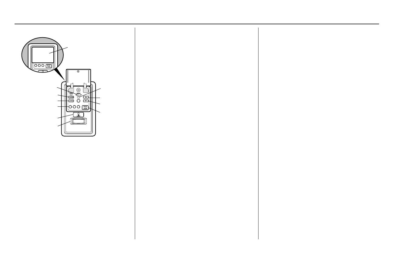
Motion Detecting Control Panel
ON (TTC)
OFF (TTC)
Command LED
Motion Sensor Switch
LIGHT Button
HOLD OPEN
But
ton(TTC)
Motion Sensor
1, 5, and 10 Minute
TTC LED
LEARN Button
LOCK Button
Push Bar
SYNCHRONIZE THE DOOR CONTROL: To synchronize the door control
to the garage door opener, press the push bar until the garage door opener
activates (it may take up to 3 presses). Test the door control by pressing the
push bar; each press of the push bar will activate the garage door opener.
PUSH BAR: Press the push bar to open or close the door.
LEARN BUTTON: Use to program compatible remote controls, wireless
keyless entries and myQ
®
devices to the garage door opener.
MOTION SENSOR: Turns the garage door opener lights on when motion is
detected. Lights stay on for 4-1/2 minutes (factory setting), then turn off. Set
the motion sensor switch ON or OFF to control this feature. The motion
sensor switch turns the motion sensor on or off.
Turn ON: Press and hold the LOCK button for 2 seconds. The command LED
will flash as long as the lock feature is on.
LOCK: Prevents remote controls from working, while still allowing
activation from the door control and keyless entry. (Factory setting is OFF.)
LIGHT BUTTON: Turns the garage door opener lights on or off when
pressed. Lights stay on for 4-1/2 minutes (factory setting). The LIGHT button
will not control the lights when the door is in motion.
To change the amount of time the lights stay on:
Press and hold the LOCK button (approximately 10 seconds) until the garage
door opener lights flash. The time interval is indicated by the number of times
the garage door opener lights flash:
l 1 flash is 1-1/2 minutes
l 2 flashes is 2-1/2 minutes
l 3 flashes is 3-1/2 minutes
l 4 flashes is 4-1/2 minutes
To cycle through the time intervals repeat the step above. If the push bar LED
is continuously blinking, the LOCK feature needs to be turned off.
To turn the light feature ON (Factory default is On):
1. Close the garage door.
2. Start with the garage door opener lights "ON".
3. Press and hold the LIGHT button (approximately 10 seconds) until
the garage door opener lights turn off, then on again.
To turn the light feature OFF:
1. Close the garage door.
2. Start with the garage door opener lights "OFF".
3. Press and hold the LIGHT button (approximately 10 seconds) until
the garage door opener lights turn off, then on again.
Turn OFF: Press and hold the LOCK button for 2 seconds. The command
LED will stop flashing and normal operation will resume.
TIMER-TO-CLOSE (TTC): DO NOT enable TTC if operating a one-piece
door. TTC is to be used ONLY with sectional doors. The TTC can be set to
close your garage door after a specified period of time (1, 5, or 10 minute
intervals). As the time to close the garage door opener occurs, the opener
beeps and the lights flash before closing the door. If an object blocks the door
while closing, the garage door opener will try to close the door again. If the
object is not removed after the second try, the garage door opener reverses
open, stop and WILL NOT close until the object is removed from the door’s
path. TTC WILL NOT work if the garage door opener is operating by battery
power or if the safety reversing sensors are misaligned. Adding a keyless
entry to control the opener is recommended to avoid an accidental lock out
when using this feature.
To turn TTC on or off or to set the TTC time interval:
Turn ON:
1. Press and hold the ON button until one of the TTC LEDs light up.
2. Then press the ON button again to cycle through the time interval
options. The TTC time interval can be set to 1, 5, and 10 minutes
(the corresponding TTC LED will light for each time interval). The
garage door opener light bulbs will blink as confirmation. Once the
TTC has been set and the door is open, the TTC LED for the
selected time interval will blink and begin to count down to close
the door.
Turn OFF:
1. Press and hold the OFF button until all TTC LEDs turn off and a
beep is heard from the garage door opener.
Temporarily hold door open (suspend TTC):
1. Press and release the HOLD OPEN button.
2. Press the HOLD OPEN button again to resume normal TTC
operation.


