8
INSTALLING THE SCANNER TO THE HOST SYSTEM
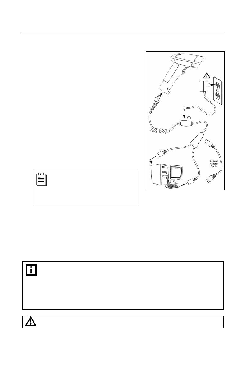
Keyboard Wedge
1. Turn off the host device.
2. Plug the 10-pin RJ45 male end of the
PowerLink cable into 10-pin socket on
the scanner. There will be an audible
click when the connector lock engages.
3. Disconnect the keyboard from the host
device.
4. Connect the “Y” ends of the
communication cable to the keyboard
and keyboard port on the host device.
If necessary use the male/female
adapter cable supplied with the scanner
for proper connections.
5. Plug the external power supply (required)
into the power jack on the PowerLink cable.
Check the AC input requirements
of the power supply to verify the
voltage matches the AC outlet. The
outlet must be located near the
equipment and be easily accessible.
6. Connect AC power to the transformer.
7. The scanner will start to initialize. All LEDs (yellow, white, and blue) will light
for approximately two seconds then start to alternately flash. When the
scanner has finished initializing the LEDs will stop flashing and the unit will
beep three times indicating that the scanner is ready for use.
8. Turn on the host device.
Plugging the scanner into a port on the host system does not guarantee that
scanned information will be communicated properly to the host system. The
scanner is shipped from the factory configured with default settings. Please
refer to the MetroSelect Single-Line Configuration Guide (MLPN 00-02544) or
MetroSet2’s help files for instructions on changing the scanner’s
configuration. In addition, please check that the scanner and host system
are using the same communication protocol.
See power source caution statement located on page 6 of this manual.
Figure 7.


