Page is loading ...

Printer Applicator System
PAM 3600
Service Manual
Edition 1/07

All specications about delivery, design, performance and weight are given to the best of our current knowledge and are
subject to change without prior notice.
W.H. Brady
Lindestraat 21
Industriepark C3
9240 Zele Belgium
Phone: +32 52 457 811
e-mail: support@brady.be
Identication Solutions Division
6555 W. Good Hope Road
PO Box 2131
Milwaukee, WI 53201 U.S.A.
Phone: 1-800-537-8791
Fax: 1-800-292-2289

3Printer Applicator System PAM 3600
Service Manual PAM 3600 Table of Contents
Table of Contents
1 Introduction ................................................................................................................................................5
1.1 Scope of Information ................................................................................................................................... 5
1.2 Important Information .................................................................................................................................. 5
1.3 General Safety Instructions ......................................................................................................................... 6
1.4 Safe Handling of Electricity .......................................................................................................................... 7
1.5 Printer Types ............................................................................................................................................... 7
1.6 Component Location ................................................................................................................................... 8
Printer .................................................................................................................................................... 8
Applicators ............................................................................................................................................. 9
Options................................................................................................................................................. 10
2 Expanded Functions for Servicing ........................................................................................................ 11
2.1 The Service Key and the OEM Key ............................................................................................................11
2.2 Expanded Functions in the "Setup" Menu ................................................................................................. 12
Print Parameters .................................................................................................................................. 12
Interfaces ............................................................................................................................................. 12
2.3 Expanded Functions in the "Test" Menu .................................................................................................... 13
Status Print .......................................................................................................................................... 13
Device List ........................................................................................................................................... 15
Label Prole ......................................................................................................................................... 16
Printhead Prole .................................................................................................................................. 16
Event Log ............................................................................................................................................. 18
Print Directory of IFFS ......................................................................................................................... 18
2.4 Expanded functions in the "Service" Menu ................................................................................................ 19
Clearing the Service Counter ............................................................................................................... 19
Adjusting the Label Edge Sensor......................................................................................................... 20
Saving the NVRAM .............................................................................................................................. 20
Loading the NVRAM ............................................................................................................................ 21
Setting the Device Name ..................................................................................................................... 21
3 Maintenance .............................................................................................................................................22
3.1 General Cleaning ...................................................................................................................................... 22
3.2 Cleaning the Printhead .............................................................................................................................. 22
3.3 Cleaning the Print Roller and the Transport System ................................................................................. 23
3.4 Cleaning the Brake .................................................................................................................................... 24
3.5 Cleaning the Pad ....................................................................................................................................... 25
4 Replacing Assembly Units......................................................................................................................26
4.1 Recommended Tools ................................................................................................................................. 26
Standard Tools ..................................................................................................................................... 26
Special Tools ........................................................................................................................................ 26
4.2 Replacing the Printhead ............................................................................................................................ 27
4.3 Replacing the Print Roller and the Feed Roller ......................................................................................... 28
4.4 Replacing the Transport Locking Roller ..................................................................................................... 29
4.5 Replacing the Pinch Roller ........................................................................................................................ 30
4.6 Replacing the Label Edge Sensor ............................................................................................................. 32
4.7 Replacing the Slip Clutches ....................................................................................................................... 33
Replacing the Slip Clutch on the Ribbon Take Up Hub ........................................................................ 34
Replacing the Slip Clutch on the Ribbon Supply Hub .......................................................................... 35
Replacing the Slip Clutch on the Internal Rewinder............................................................................. 35
4.8 Replacing the Main Drive Motor ................................................................................................................ 36
4.9 Replacing the CPU PCB ............................................................................................................................ 37
4.10 Replacing the Power Unit .......................................................................................................................... 39
4.11 Replacing the Applicator Control PCB and Firmware Update of the Applicator Module ............................ 40
4.12 Replacing the Sensors .............................................................................................................................. 41
Sensors of the Printer Module ............................................................................................................. 41
Sensors of the Applicator Module ........................................................................................................ 46
4.13 Disassembling the Energy-Chains ............................................................................................................ 47
5 Adjustments .............................................................................................................................................48
5.1 Adjusting the Peel-off Table ....................................................................................................................... 48
5.2 Adjusting the Printhead ............................................................................................................................. 49

4
Printer Applicator System PAM 3600
Service Manual PAM 3600Table of Contents
5.3 Adjusting the Guide Plate .......................................................................................................................... 50
5.4 Adjusting the Sensors of the Peel-off Table ............................................................................................... 51
5.5 Adjusting the Sensors of the Printhead ..................................................................................................... 52
5.6 Adjusting the Torques at the Hubs ............................................................................................................. 53
Measuring the Traction at the Internal Rewinder ................................................................................. 53
Measuring the Traction at the Ribbon Take Up and the Ribbon Supply Hub ....................................... 54
Adjusting the Torques .......................................................................................................................... 55
5.7 Adjusting the Brake at the Media Supply Hub ........................................................................................... 56
5.8 Adjusting the Label Edge Sensor .............................................................................................................. 57
5.9 Setting the Speed of the Compressed Air Driven Assemblies ................................................................... 57
Setting the Speed of the Peel-off Table Movement .............................................................................. 57
Setting the Speed of the Printhead Movement .................................................................................... 58
Setting the Speed of the Turn/Lift Cylinder Movement ........................................................................ 59
Setting the Speed of the Main Cylinder Movement.............................................................................. 60
5.10 Pneumatic Setting of the Printhead Pressure ............................................................................................ 61
5.11 Pneumatic Setting of the Brake ................................................................................................................. 62
5.12 Pneumatic Setting of the Supporting Air .................................................................................................... 63
5.13 Pneumatic Setting of the Table .................................................................................................................. 64
5.14 Adjusting the Sensors of the Applicator Module ........................................................................................ 65
Adjusting the Sensor Turn/Lift Cylinder................................................................................................ 65
Adjusting the Labeling Position Sensor ............................................................................................... 66
Adjusting the Sensor 1 Main Cylinder .................................................................................................. 67
Adjusting the Sensors 2 Main Cylinder (PAM 3602 only) .................................................................... 68
6 Problem Solution .....................................................................................................................................69
6.1 Errors During Printing ................................................................................................................................ 69
6.2 Failure of Device Functions ....................................................................................................................... 71
6.3 Permanently Displayed Hardware Errors .................................................................................................. 72
Appendix A: Block Diagram ............................................................................................................................. A-1
Appendix B: Circuit Diagrams ......................................................................................................................... B-1
PCB CPU: CPU, Clock Timer, Clock, BDM..........................................................................................................B-1
PCB CPU: Centronics, Interface Slot, RS-232 ....................................................................................................B-2
PCB CPU: dRAM, Flash ......................................................................................................................................B-3
PCB CPU: Printhead Connection ........................................................................................................................B-4
PCB CPU: FPGA, History RAM ...........................................................................................................................B-5
PCB CPU: Power Supply, Motor Driver ...............................................................................................................B-6
PCB CPU: Sensors, AD Converter ......................................................................................................................B-7
PCB CPU: USB Host ...........................................................................................................................................B-8
PCB 1 Control Panel ............................................................................................................................................B-9
PCB Control Panel .............................................................................................................................................B-10
PCB Applicator Control: Controller.....................................................................................................................B-11
PCB Applicator Control: Inputs/Outputs .............................................................................................................B-12
PCB Valve Connection .......................................................................................................................................B-13
PCB Ribbon Sensor ...........................................................................................................................................B-13
Appendix C: Layout Diagrams......................................................................................................................... C-1
PCB CPU: Components side .............................................................................................................................. C-1
PCB CPU: Soldering side ................................................................................................................................... C-2
PCB 1 Control Panel: Components side ............................................................................................................. C-3
PCB 1 Control Panel: Soldering side .................................................................................................................. C-3
PCB Control Panel .............................................................................................................................................. C-3
PCB Applicator Control: Components side ......................................................................................................... C-4
PCB Applicator control: Soldering side ............................................................................................................... C-4
PCB Valve Connection ........................................................................................................................................ C-5
PCB Ribbon Sensor: Components side .............................................................................................................. C-5
PCB Ribbon Sensor: Soldering side ................................................................................................................... C-5
Appendix D: Pneumatic Diagrams .................................................................................................................. D-1
PAM 3600 with Applicator 3602 .......................................................................................................................... D-1
PAM 3600 with Applicator 3603 .......................................................................................................................... D-2
Index I-1

5
Printer Applicator System PAM 3600
Service Manual PAM 3600 1 Introduction
1 Introduction
1.1 Scope of Information
This manual is intended for use by qualied service and maintenance personnel.
The technical information included relates to hardware and mechanical parts of the Printer Applicator System PAM
3600.
Information related to operation will be found in the Operator's Manual.
If a problem occurs, which cannot be solved with the help of this manual, please contact the Technical Service
Department.
To adress see page 2.
1.2 Important Information
Important information contained in this manual is marked as follows:
WARNING!
Impending danger!
May cause death or physical injuries.
CAUTION!
Dangerous situation!
May cause equipment/material damage or data loss.
NOTICE!
Helpful additional information and tips for use.
In special cases a second symbol is additionally used to characterize the kind of danger.
See a sample for the risk of electric shock:
WARNING!
Mortal danger by electric shock!
Unplug power cord before opening the cover!

6
Printer Applicator System PAM 3600
Service Manual PAM 36001 Introduction
1.3 General Safety Instructions
Follow the general safety rules below:
Keep the area around the device clean at all times!
Avoid performing maintenance which might expose persons to danger or make the device a source of danger!
Keep housing or other parts of the device removed in a safe place during maintenance!
Keep tools out of the way to avoid injury to yourself or others not involved in the maintenance!
Do not wear loose clothing that could be caught in moving parts of the device. Button up your shirt or jacket
sleeves or roll them up. Tie back or put up long hair. Tuck the ends of scarves, ties and shawls into your
clothing and attach them with a non-conducting clip.
Do not wear jewelry, glasses with metal frame or clothing with metal fasteners!
WARNING!
Mortal danger by electric shock!
If such metal parts contact the device, they cause an increased current ow due to
good conductivity!
Wear protective goggles at work as follows:
while driving pins or similar parts in or out with a hammer,
while working at an electric drilling machine,
while using spring hooks or springs,
while releasing or using of springs, snap rings and grip rings,
while soldering,
while using solvents, cleansers or other chemical substances,
in any case where injury to the eyes is possible.
Ret all protective devices such as covers, safety instructions, and grounding cable upon completion of the
maintenance work!
Replace all faulty or defective parts!
•
•
•
•
•
•
•
-
-
-
-
-
-
-
•

7
Printer Applicator System PAM 3600
Service Manual PAM 3600 1 Introduction
1.4 Safe Handling of Electricity
Follow the additional instructions below when handling electricity:
Find out the positions of the emergency and the power switch in order to operate them quickly in an emergency
situation!
Do not work alone under dangerous working conditions or while working on devices with non-protected
voltages (over 50 V AC or 120 V DC)!
Turn off power to the printer before:
removing or installing power units,
working in the immediate vicinity of open power supply parts,
mechanical checkup of power supply parts,
changing circuit boards or electrical parts.
If you cannot avoid working on devices with non-protected voltages, follow these safety precautions:
Have a person nearby who is aware of the position and operation of the power switches, who will switch off
the power in case of danger.
Use only tools and test devices, which are suitable for the work being done.
Work only with one hand on devices that are switched on. Keep the other hand behind your back or in your
pocket until you have nished.
NOTICE!
A shock occurs only with a closed circuit. By using only one hand, as described above, you
would avoid a current ow through your own body.
Do not use worn or defective tools!
Never assume that a circuit is not powered. Always verify that there is no voltage present!
Always examine the work area for possible sources of danger, such as wet oors, defective extension cords,
faulty protective grounding connectors etc.
If you observe an accident with electricity:
Be careful and avoid danger to yourself.
Switch off power.
Request medical assistance.
Give rst aid if necessary.
1.5 Printer Types
There are two printers for the PAM 3600 systems available:
PAM 3630 with a printhead resolution of 300 dpi and
PAM 3660 with a printhead resolution of 600 dpi.
Both printers can be equipped with one of the applicator types
PAM 3602, tamp-blow applicator with vertical lift (main) cylinder and turn cylinder and
PAM 3603, tamp-blow applicator with vertical lift (main) cylinder and horizontal lift cylinder.
•
•
•
-
-
-
-
•
-
-
-
•
•
•
•
-
-
-
-
•
•
•
•

8
Printer Applicator System PAM 3600
Service Manual PAM 36001 Introduction
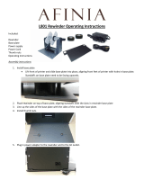
1.6 Component Location
Printer
Figure 1a Overview printer
1 Ribbon take up hub
2 Control panel and display
3 Ribbon supply hub
4 Swing arm with guide roller
5 Guide roller
6 Media supply hub
7 Internal rewinder
8 Power connector
9 Power switch
10 Compressed air connector
11 Silencers
12 Frame
13 Sensor connector for the applicator
14 Compressed air connectors for the applicator
15 Printhead
16 Print roller
17 Peel-off table
18 Guide roller
19 Slot for an additional interface card
20 Connector warning sensor ribbon end
21 Connector warning sensor label end
22 PLC interface port
23 Connector warning light
24 RS-232 interface
25 USB master interface
26 Bi-directional parallel interface
27 Cover
21 22 23 24 25 26 272019
17 18
1 3 4 5 6 7
8
9
2
1110 12 1413
1615

9
Printer Applicator System PAM 3600
Service Manual PAM 3600 1 Introduction
Applicators
PAM 3602 PAM 3603
Figure 1b Overview applicators
1 Energy-chains
2 Sensor 1 main cylinder
3 Main cylinder
4 Sensor 2 main cylinder (PAM 3602 only)
5 Slide valve
6 Lift cylinder (PAM 3603 only)
7 Turn cylinder (PAM 3602 only)
8 Pad holder
9 Pad
1
2
4
3
4
5
8
9
7
6

10 Printer Applicator System PAM 3600
Service Manual PAM 36001 Introduction
Options
Figure 1c Overview options
1 Warning light
2 Warning sensor, ribbon end
3 Warning sensor, label end
4 Antistatic burst
5 Blow tube
1
2
3
4
5

11Printer Applicator System PAM 3600
Service Manual PAM 3600 2 Expanded Functions for Servicing
2 Expanded Functions for Servicing
2.1 The Service Key and the OEM Key
There are a service key (Part No. 5540301) and an OEM key (Part No. 5540304) for accessing special service
functions which are not accessible to the operator.
The OEM key enables:
selecting the correct device name (Set OEM Name).
The service key enables, among other functions:
adjustment of the label edge sensor,
clearing the service counters,
printing an expanded status report,
printing an event log,
saving the conguration data on a memory module (Save NVRAM),
loading the conguration data from a memory module (Load NVRAM).
Moreover, the conguration parameters stored in the printer for optional components (interface boards) are
also accessible with the service key inserted, even if they are not currently installed.
The information contained in the test printout is also expanded.
The printer offers the option of protecting certain functions - such as the complete printer conguration and
security-relevant memory module functions - from unauthorized access by means of a code number (PIN).
There is no PIN prompt when accessing the stated functions with the service key inserted, i. e. the protective
function is circumvented.
NOTICE!
Please ask your cab dealer about obtaining the service key or the OEM key.
Insert the respective key (1) into the USB master interface (2) on the side of the printer. This can be done while the
device is switched on.
21
Figure 2a Inserting the service key or the OEM key
1 Key
2 USB master interface
•
•
•
•
•
•
•

12
Printer Applicator System PAM 3600
Service Manual PAM 36002 Expanded Functions for Servicing
2.2 Expanded Functions in the "Setup" Menu
There are a variety of parameters that can be set to congure the printer to specic requirements.
There are three different methods to set the parameters of the Printer Conguration:
Conguration via the control panel (see Operator's Manual),
Conguration via the optional Ethernet interface accessing the internal web server of the printer using a Java
enabled browser (see Operator's Manual of the optional Ethernet interface),
Conguration via immediate commands (described in the Programming Manual, chapter "Immediate
Commands").
Print Parameters
Protocol Error
With the service key inserted, the parameter "Protocol error" is accessible in the "Print parameters" submenu.
The protocol error parameter is "ON" in the standard setting. As a result, the printer switches to the error state after
receiving unknown or faulty data.
When working with older computer operating systems, it may happen that the operating system’s print spooler
sends normal printer status messages (e.g. end of paper) back to the printer as ASCII text.
The printer cannot interpret this data and produces a long series of protocol errors. The protocol error display can
be switched off in such a case.
CAUTION!
Data loss!
Protocol errors arising from faulty programming are also ignored in the "OFF" setting. There is a
risk of losing data.
Insert the service key into the Master USB socket.
Switch from online mode to the ofine menu by pressing the key.
Press the or key until you reach the "Setup" menu, and then press the key.
Now select the "Print parameters" submenu and then the "Protocol error" parameter, then press the key.
Set the parameter according to your requirements.
Interfaces
The following parameters can be called or congured in the "Interfaces" submenu:
Character set,
IEEE1284,
RS-232.
If the optional interfaces
RS-422/485,
Ethernet and
Keyboard
are installed then these are also shown for setting.
NOTICE!
The parameters of the options "RS-422/485 interface", "Ethernet interface" and "Keyboard" can
be accessed with the service key, even if these components are not present.
Please refer to the "Printer Conguration" section of the printer or optional component operator's manuals for
instructions on how to perform the conguration and set the parameters.
•
•
•
1.
2.
3.
4.
5.
•
•
•
•
•
•

13
Printer Applicator System PAM 3600
Service Manual PAM 3600 2 Expanded Functions for Servicing
2.3 Expanded Functions in the "Test" Menu
The test functions allow the operator or the service personnel to obtain an overview of the most important printer
settings and hardware congurations.
The following functions can be called in the "Test" menu.
Short status*
Status print
Font list*
Device list
ASCII dump mode*
Test grid*
Label prole
Printhead prole
Event log
IFFS Print directory
NOTICE!
For functions marked with an * refer to the Operator's Manual. You will nd all the information
you need there.
Additional information to the Operator's Manual about the other test functions you will nd in
this section.
In order to reach the "Test" submenu, use the key to switch from online mode to the ofine menu.
Press the or key until you reach the "Test" menu, and then press the key.
Now select the desired test function.
Status Print
The status print contains information about the printer conguration and the status.
It will be printed with the heat level and the print speed set in the "Setup" menu.
NOTICE!
With the service key inserted, the status print also contains parameter settings of optional
components, even if these have not been installed and the values of the service counters.
You obtain the expanded status print as follows:
Insert the service key into the Master USB socket.
Switch from online mode to the ofine menu by pressing the key.
Press the key or until you reach the "Test" menu, and then press the key.
Select the "Status print" function with the or key and conrm with the key.
Start the printout with the pre-dispense key.
The printout can be aborted with the key.
The status printout contains the following information:
A Device type, version and date of the rmware
B Values of selected conguration parameters
C Switch-on time, number of prints and the print length, values of the service counters
D Printhead temperature, heating voltage
E Details about the working points of the label edge sensor
F Line pattern for evaluating the quality of the printed image
O Parameter settings of optional components
A typical status printout is shown in the following gure.
•
•
•
•
•
•
•
•
•
•
1.
2.
3.
4.

14
Printer Applicator System PAM 3600
Service Manual PAM 36002 Expanded Functions for Servicing
D
C
B
A
F
E
O
O
Figure 2b Status Print with Service Key inserted

15
Printer Applicator System PAM 3600
Service Manual PAM 3600 2 Expanded Functions for Servicing
Device List
The most important hardware components installed in the printer and the connected optional devices are listed in
the "Device list" submenu.
Please also refer to the "Test Functions" section of the Operator's Manual for the printout of the device list and
further information.
Proceed as follows to print the device list:
Insert the service key into the Master USB socket.
Switch from online mode to the ofine menu by pressing the key.
Press the or key until you reach the "Test" menu, and then press the key.
Select the "Device list" function with the or key and conrm with the key.
Start the printout with the pre-dispense key.
The printout can be aborted with the key.
The printout contains the following information:
CPU Type and serial number of the CPU PCB, revision number of the CPU PCB and FPGA
TPH Resolution and number of hot points of the thermal printhead
CARD* Capacity, manufacturer, serial number and version number of the FlashCard
SLOT* Type, serial number and revision number of the interfaces expansion card
USB [a]* Type and revision number of the installed
[b/c] s USB devices
a: Number of the USB device
b: Number of the USB device to which device a is connected
c: Port number of device b, to which device a is connected
s: Speed of the USB device (Low Speed or Full Speed)
Only with inserted service key:
Mfr. Manufacturer ID indicates the manufacturer of the USB device
Class Code number for the USB device class
Protocol Code number for the type of communication with the USB device
Phase Internal value for debugging purposes
(* This information is only printed if the corresponding devices are installed.)
Figure 2c Device List with Service Key inserted
1.
2.
3.
4.

16
Printer Applicator System PAM 3600
Service Manual PAM 36002 Expanded Functions for Servicing
Label Prole
The label prole printout contains additional information with the service key inserted.
Print out the label prole as follows:
Insert the service key into the Master USB socket.
Select the "Test" menu in the ofine menu and conrm with the key.
Press the or key until you reach the "Label prole" function and conrm with the key.
Start the printout with the pre-dispense key.
The printout can be aborted with the key.
5
6
7
8
9
1
2
3
4
Figure 2d Label Prole with Service Key inserted
1 Device name and current rmware version
2 Method of label detection (transmitted light/reex bottom)
3 Print speed and service information for adjusting the label sensor
4 Scale factor for the derivative diagram *
5 Coordinate in the direction of paper ow at which the label start was detected
6 Type of peripheral device connected
7 Information for the rmware developer
8 Stroke between start and end of the negative derivative *
9 Width of the negative derivative in motor increments *
Information marked with * are only available with the service key inserted.
Printhead Prole
When selecting the option "Printhead prole", a diagram will be printed which shows the resistance values for the
single printhead dots. This printout makes it possible to see the status of the printhead.
When a dot is damaged or defective its resistance value increases. When this error occurs, it causes white lines in
the print image from top to bottom. In some cases, the white line could cause an invalid scan of certain barcodes.
To print the printhead prole, load media (labels, continuous paper) and a transfer ribbon (if applicable), which
extends over the entire print width of the printer.
NOTICE!
With "Printhead prole", the printer will not sense any label gaps, and will print non-stop.
Continuous paper works best for the prints.
1.
2.
3.

17
Printer Applicator System PAM 3600
Service Manual PAM 3600 2 Expanded Functions for Servicing
Insert the service key into the Master USB socket.
Switch from online mode to the ofine menu by pressing the key.
Select the "Test" menu in the ofine menu and conrm with the key.
Select the option "Printhead prole" by pressing the key or the key and conrm by pressing the key.
NOTICE!
The measurement of the resistance values can take several minutes.
You will see the progress of this measurement on the display.
5. When the measurement has nished, start the printout by pressing the pre-dispense key.
6. The "Printhead prole" will be printed with the heat level and print speed set in the "Setup" menu.
To cancel the print, press the key.
The printout has a scale which marks the actual geometric position of the dots. The scale will be printed underneath
the black bar with the text "Printhead prole". It is possible to compare a single dot to the scale as demonstrated in
the following diagram.
The gure indicates a print image failure around 22.5 mm in the black bar. In the scale section of the diagram, a dot
with an increased resistance value appears around 22.5 mm. Using this comparison makes it clear that the image
fault on the top line is caused by a defective printhead and not a case of a dirty printhead surface.
Figure 2e Printhead Prole with Service Key inserted
1.
2.
3.
4.

18
Printer Applicator System PAM 3600
Service Manual PAM 3600
Event Log
The label printer stores the following events in the event log:
Hardware fault
Adjustment of the label sensor
Firmware updates
Service counters reset
The event log can only be called with the service key inserted.
Print out the event log as follows:
Insert the service key into the Master USB socket.
Select the "Test" menu in the ofine menu and conrm with the key.
Press the or key until you reach the "Event log" function and conrm by pressing the key.
Start the printout by pressing the pre-dispense key.
The printout can be aborted with the key.
Figure 2f Event log
Print Directory of IFFS
The IFFS (Internal Flash File System) is located on a Flash EPROM in the printer.
NOTICE!
As long as there was no write access on the IFFS the function "Print directory" is not shown.
The function "Print directory" can only be called with the service key inserted.
Start the printout of the directory as follows:
Insert the service key into the Master USB socket.
Select the "Test" menu in the ofine menu and conrm with the key.
Press the or key until you reach the "Print directory" function and conrm by pressing the key.
Start the printout by pressing the pre-dispense key.
The printout can be aborted with the key.
From the printout you can get the following information:
First line: headline
For each le in the IFFS one line is printed with information about le name, le type, size of le in byte, date
and time for last change of le.
Last line: free memory in IFFS
Directory of internal Flash:
DEFAULT LBL 786 16.06.04 17:10
64718 bytes free
Figure 2g Printout Directory of IFFS
•
•
•
•
1.
2.
3.
1.
2.
3.
•
•
•
2 Expanded Functions for Servicing

19
Printer Applicator System PAM 3600
Service Manual PAM 3600 2 Expanded Functions for Servicing
2.4 Expanded functions in the "Service" Menu
In the "Service" menu, the operator only has access to the "Firmware update" and "Firmware from card" function.
The following functions are available after the service key respective the OEM key have been inserted:
Firmware update
Firmware from card*
Clear service counter
Adjust gap sensor
Save NVRAM*
Load NVRAM*
Set OEM Name
Functions marked with * are only available if the CF memory card is installed.
Clearing the Service Counter
The printer has two counter sets, a total and a service counter. The following data is recorded in both counter sets:
Operative time: time the printer has been switched on
Number of labels: number of labels printed
Transfer print: length of material printed in transfer print
Thermal direct: length of material printed in direct thermal print
The total counter contains the values for the total elapsed service life of the printer. The values of the total counter
are shown in both the short status and in the status printout.
The service counter can be reset with the use of the service key after major maintenance or repair work.
The service counter consequently provides information about the print output since the last reset.
The service counter is reset as follows:
Switch from online mode to the ofine menu by pressing the key.
Press the or key until you reach the "Service" menu, and then press the key.
Now select the "Clear service counter" function, and then press the key.
"No" appears in the display. Change the selection to "Yes" with or and press .
This resets the service counter.
You can check the value reset in the status printout.
1.
2.
3.
4.

20 Printer Applicator System PAM 3600
Service Manual PAM 36002 Expanded Functions for Servicing
Adjusting the Label Edge Sensor
The function "Adjust gap sensor" enables the label edge sensor to be adjusted. This is necessary when the label
edge sensor itself or the CPU PCB are replaced.
NOTICE!
In order to avoid the inuence of light from the outside, check the adjustment of the sensor with
the cover closed and housing mounted!
Perform the adjustment as follows:
Insert the service key into the Master USB socket.
Select the "Service" menu in the ofine menu and conrm with the key.
Select the "Adjust gap sensor" function in the "Service" menu and conrm with the key.
Open the printhead.
The request "Please remove label stock" from label edge sensor appears in the display. Obey the request,
close the printhead and conrm with the key.
The display now requests "Please insert liner" into the label edge sensor.
Insert the liner material (without labels) into the label edge sensor, lock the printhead and conrm with the
key.
NOTICE!
Ensure that there are not any labels on the liner in the vicinity of the label edge sensor. This
would lead to a faulty alignment and a device malfunction.
7. "OK" appears in the display when the adjustment has been successful. Press the key again. The adjustment
has been completed now.
The message "Error" appears in the display if a fault occurs during the adjustment. If a fault recurs when the
adjustment is repeated, then there could be a defect in the following components:
Label edge sensor,
Label edge sensor connection cable or
CPU PCB.
Saving the NVRAM
The "Save NVRAM" function is used to save a printer conguration on a CompactFlash memory module.
This function is only accessible with the service key inserted and the CF card in the slot.
Save on the NVRAM as follows:
The printer is switched on.
Insert a CF card into the CF slot.
Insert the service key into the Master USB socket.
Select the "Save NVRAM" function in the "Service" menu and press the key.
"No" appears in the display.
Change the selection to "Yes" with or and press the key. The saving begins and is indicated by the
green LED next to the CF slot.
CAUTION!
Data loss!
Do not press the ejection key for the CF card while the green LED is lit.
If an error message appears in the display, this may indicate an unreadable CF card (e.g. unknown card type,
unformated card).
NOTICE!
To format the CompactFlash memory module, please refer to the "Memory Modules" section of
the Operator's Manual.
1.
2.
3.
4.
5.
6.
•
•
•
1.
2.
3.
4.
/