Page is loading ...


IMPORTANT - READ CAREFULLY
The Dixon ZTR Mower is both easy and fun to operate. However, any power mower must be
operated properly to be safe. It is not a toy or a recreational vehicle. Before you start to use
the mower, read the operator's manual carefully, and become completely familiar with the
controls.
The information in this operator's manual applies to all Dixon ZTR Model 5501 Mowers. Your
Dixon dealer will gladly provide a check-out ride, and answer any questions.
See your dealer for warranty service, parts and repairs.
DIXON INDUSTRIES, INC. A
BLOUNT COMPANY AIRPORT
INDUSTRIAL PARK PO BOX 1569
COFFEYVILLE KS 67337 0945
316251 2000 FAX 316 251 4117

INDEX
1. SAFETY ............................................................... Pages 1- 3
2. WARRANTY POLICY .......................................... Page 4
3. SPECIFICATIONS................................................ Page 5
4. SET UP AND SERVICE ....................................... Pages 6 - 12
5. OPERATION INSTRUCTIONS............................. Pages 13- 14
6. CARE AND MAINTENANCE ................................ Pages 15-22
7. TROUBLESHOOTING ......................................... Pages 23-25
8. PARTS ILLUSTRATIONS..................................... Pages 26-32
9. PARTS LIST ......................................................... Pages 33-36

SAFETY
RIDING LAWNMOWERS, IF IMPROPERLY OPERATED,
CAN CAUSE SERIOUS INJURY
The following examples are the most common causes of injury to the
operator or bystander...
1 . BLADE CONTACT:
The operator or bystander inserts a hand or foot into the discharge chute
or under the mower deck and into the path of the cutting blade. Neve
r
run the mower blades when there are people nearby. Always turn the
engine off when cleaning or working around the mower deck.
2. RUN-OVER:
This situation occurs when a bystander is run-
over or backed over by the
mower. The most frequently cited example
s are with small children who
wander into, or are allowed to play in an area where the mower is being
operated. Never run the mower blades when there are people nearby,
especially children. Young children should be indoors and watched by
an adult. Always look behind you before backing up.
3. TIP-OVER:
This occurs when the mower tips over, usually sideways or to the rear.
This situation is due to operation of the mower on steep inclines or near
a drop-off. Mow across the slope to slightly uphill. Mow slopes
when
the grass is dry and watch for bumps, holes and other obstacles. Test
the slope with the blades off. A good rule of thumb is "Don't mow on a
slope you can't back up". Stay clear of drop-
offs, especially if they are
on the down side of a slope.
4. THROWN OBJECTS:
The fast spinning mower deck blade can strike stones or other objects
which can be hurled into the path of a bystander. To prevent this from
happening, never remove the safety discharge chute from the mower
deck, or operate the mower when other people are around.
5. FIRES:
Most accidents of this type occur during re-
fueling of the mower or
placing the mower in a storage situation. The exhaust system and
related engine components operate at very high temperatures which
can ignite any fuel spil
led on or near them. Always allow the mower to
cool before re-fueling or placing in storage.
6. OPERATION BY
CHILDREN:
This mower is not a toy or a recreational vehicle. Never allow children
to operate the mower in any manner or to ride as a passenger.
NOTE: The six examples are the most frequently cited injury causing situations. Please review
all the safety precautions outlined on the following pages prior to operation of the
mower. Our aim is to enhance the safe and satisfactory use of this product.
Page 1

SAFETY
SAFETY REMINDERS: READ CAREFULLY BEFORE OPERATION
1.
Wear appropriate, safe clothing when mowing - close fitting jeans or slacks and heavy leather
or safety shoes with rough soles. Never operate this mower with bare feet or open sandals.
2.
Do not operate on wet or slippery grass.
3.
Always mow at the slowest speed that will cut satisfactorily.
4.
Keep hands and feet away from the blade at all times.
5.
Keep persons clear of the discharge chute. Do not operate mower unless deflector is in place.
6.
When mowing hills or slopes, use extreme caution. Reduce speed, do not make sudden starts,
stops or turns.
7.
Always disengage blades before taking the mower across walks or objects that project above
the surface.
8.
Stay alert for holes, rocks and roots in the terrain, and other hazards. Keep away from
drop-offs.
9.
When the mower is not in use, turn the engine off and remove key. Never leave the engine
running unattended. Your Dixon mower is equipped with a weight-sensitive switch that kills the
engine when operator leaves the seat while blades are engaged.
Note:
This important safety feature must be tested prior to each mowing. This may be done by starting
engine, engaging blades and then rising slightly from seat. If engine does not stop, see your
dealer for necessary repair.
10.
Before adjusting or servicing your mower, turn off the engine and let it cool. Be sure all moving
parts are stopped. Never run the 5501 with the body open.
11.
Never run the engine indoors; the fumes are dangerous.
12.
Before backing your Dixon Mower; stop, turn around and look.
13.
Handle gasoline with care - it is highly flammable.
A. Use approved gasoline container.
B. Never remove the fuel cap of, or add gasoline to, a running or hot engine, or
an engine that has not been allowed to cool after running. Never fill the tank
indoors and always clean up spilled gasoline.
C. Never store the mower, with gasoline in the tank, inside the building where
fumes may reach an open flame or spark. Allow the engine to cool before storing
in any enclosure.
Page 2

SAFETY REMINDERS:
(Continued)
14.
Never lift lawnmower by the body, lift only by the frame.
15.
Never carry passengers.
16.
Use care when pulling loads or using heavy equipment.
A. Use ONLY approved drawbar hitch points.
B. Limit loads to those you can safely control.
C. Do not turn sharply. Use care when backing.
17.
Watch out for traffic when crossing or near roadways.
18.
Keep the mower in good operating condition, and keep safety devices in place and working.
19.
Keep all nuts, bolts and screws tight to be sure the mower is in safe working condition.
20.
To reduce fire hazard, keep the engine free of grass, leaves or excessive grease.
21.
The mower should be stopped and inspected for damage after striking a foreign object or if it
starts vibrating, and any damage should be repaired before restarting and operating the mower.
22.
When mowing, proceed as follows:
A.
Mow only in daylight or in good artificial light.
B. Shut the engine off when removing the grass catcher or unclogging chute.
C. Check the blade mounting bolts for proper tightness at frequent intervals.
D. Never operate the machine when using medication or under the influence of alcohol
or drugs.
Page 3

DIXON LIMITED WARRANTY POLICY - HYDRO-GEAR MODELS
This warranty policy applies to all Hydro-Gear mowers or any 50" model, purchased on or after March 1,1990.
WARRANTY: Dixon Warranty term is for a period of one (1) year from date of purchase or 400 hours of use, whichever
occurs first. Mowers used for residential homeowner applications (used only at owner's primary place of residence) are
warranted for two (2) years from date of purchase or 400 hours of use, whichever occurs first. DIXON ZTR MOWERS
ARE WARRANTED AGAINST DEFECTS IN MATERIALS AND WORKMANSHIP AND PROVIDES FOR REPLACEMENT
OR REPAIR OF PARTS INCLUDING LABOR COSTS. THIS WARRANTY IS SUBJECT TO THE FOLLOWING
CONDITIONS AND LIMITATIONS:
1. Warranty applies only to original retail purchaser of new and unused mowers and accessories.
2. All Dixon warranty must be accomplished by authorized Dixon dealers and in accordance with Dixon warranty policy and
allowances. All warranty claims must be approved by Dixon Industries, Inc.
3. Battery warranty: Limited to 90 days from date of purchase.
4. Accessories Warranty (Grass Catchers, Snow Blades, Tine Rakes, Covers, etc.): Limited to 90 days from date of purchase.
5. Warranty does not apply to damage in transit or incidents of misuse, negligence, accidents, or alteration. The use of parts
or components other than those supplied by Dixon Industries, Inc. VOIDS ALL WARRANTY.
6. The following items are not covered by this warranty policy:
(a) Pick up and delivery charges for transportation of mower to and from an Authorized Dixon Dealer's place of business.
(b) Routine maintenance or adjustments.
(c) Belts / chains / sprockets / cutting blades.
(d) Engines -- All engines used on Dixon ZTR mowers are warranted by each individual engine manufacturer.
(e) Any costs or expense of providing substitute equipment while repair work is being performed on a warranted mower.
7.
There is no other express warranty. Implied warranties, including those of merchantability and fitness for a particular
purpose, are limited to the same duration of the express warranty, and to the extent permitted by law any and all implied
warranties are excluded. Liabilities for consequential damages under any and all warranties are excluded.
WARRANTY VALIDATION: At the time of sale, selling dealer must review each portion of this warranty document, complete the
information section below, secure customer's signature and send copy to Dixon Industries, Inc.
Page 4

SPECIFICATIONS
CHASSIS:
11 GA - rectangular tube.
BODY:
Two piece -
made of rotational molded polyethylene. Front body contains access
panels for battery service and engine to mower deck belt removal. Rear body
tilts up to allow service on the entire drive system.
SEAT:
Economically designed for opera
tor comfort by use of high density closed cell
foam, contoured back rest and arm rests. Seat is adjustable fore and aft.
MOWER DECK:
12 GA stamped steel construction, 3 blades, 50" cut width, cut height approximately
1" to 4" via 7 position lift handle.
BLADE DRIVE:
Electric clutch.
DRIVE SYSTEM:
Each rear wheel is independently driven by a Hydro Gear BDU-
10L Series 70
hydrostatic transmission. The hydrostatic transmissions, in turn, power a fully
enclosed Hydro Gear gearbox. The gears in the Hydro Gear
gearbox are
permanently lubricated using a special grease which completely eliminates the
need for any type of maintenance.
The Hydro Gear BDU-
1 OL Series 70 hydrostatic transmissions are serviced with
any high quality 10W-30 motor oil. The oil is filter
ed by a 10 micron oil filter.
Recommended service interval for filter is after the first 250 hours of operation,
then after every 400 hours of operation. If the system becomes contaminated by
dirt or other foreign debris, both oil and filter must be replaced immediately.
ENGINE:
20 HP Kohler Magnum, Vertical Crankshaft, 4-
Cycle, Air Cooled, Gasoline, Twin
Cylinder Opposed, Aluminum Crankcase, Removable Cast Iron Cylinder Barrels,
Electronic Ignition, Full Pressure Lubrication.
STARTING SYSTEM:
Electric by
key switch operation with safety interlocks on parking brake and blade
drive clutch.
TIRES:
Front 11 X 4.10 X 5 smooth profile.
Rear 20 X 1 0 X 8 turf savers.
CAPACITIES:
Fuel - 4.8 gallons total (dual tanks). Hydrostat oil tank - 3 quart with i
nline 10
micron filter. Hydrostat oil recommendation - name brand SAE 10W-
30 motor
oil.
DIMENSIONS:
Width 60"
Height 45"
Length 72"
Weight 668 Ibs.
NOTE:
Additional information provided in service instructions under the individua
l
component.
SPECIFICATIONS SUBJECT TO CHANGE WITHOUT NOTICE.
PageS

Page 6
SET UP AND SERVICE
1. Seat Assembly Instructions
2. Upper Control Lever Installation
3. Mower Deck Installation
4. Deck Leveling
5. Final Preparation

SEAT ASSEMBLY INSTRUCTIONS
1.
Place seat back against frame of seat bottom. Align top & bottom holes in frame with the t-nuts in
seat back. Insert (4) 1/4-20 Phillips machine screws to attach frame to seat back. DO NOT
TIGHTEN SECURELY.
2.
Place (1) armrest bracket against seat back, aligning mounting holes in bracket and seat back.
3.
Insert (2) 5/16-18 X 5/8" tapping screws through holes in bracket & frame and start screw threads.
DO NOT TIGHTEN SECURELY.
4.
Insert (1) 1/4-20 X 3/4" Phillips machine screw through remaining hole in bracket and start screw
threads. DO NOT TIGHTEN SECURELY.
5.
Repeat steps 2 through 4 for the other armrest.
6.
Tighten all screws.
7.
Align back cover to seat back. Secure with (4) #14 X 5/8" wood screws and (4) 5/16" SAE washers
in recesses provided.
8.
Slide armrest onto mounting bracket pin.
9.
Insert set screw in rear of armrest, securing armrest to mounting bracket.
10.
Repeat steps 8 & 9 for other armrest.
11.
Center utility box on seat back cover and fasten with drill & tap screws and washers provided in
separate hardware package.
Page 7

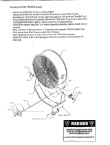
12
.
Install all-thread hex head bolts into seat straps.
Place (1) 5/16-18 x 3" bolt through hole located 1
-5/8" from end of strap. Place (1 ) 5/1 6-1 8 x 4" bolt
through hole located 2-7/8" from opposite end of
strap. Secure each bolt to strap using (1) 1/8"
thick washer and (1) 5/16-18 hex nut w/nylok. See
illustration. Repeat procedure for other seat strap.
13
.
Attach seat straps to seat bottom as illustrated.
The 3" stud protruding through strap must be
located near the rear of seat while the 4" stud
should be nearest the front edge of seat. Align
remaining seat strap holes with holes in bottom
of seat as shown, and attach seat straps using
(4) 5/1 6-18X1 " tapping screws.
14
.
Place seat assembly on body, and
connect
safety switch.
15
.
Place (1) seat spacer (1849) on each stud
protruding through seat bottom, and insert studs
through slots in body. Firmly hold seat assembly
against body with one hand while body is raised to
fully open position. Continue to hold seat against
body to prevent damage to seat safety switch
wiring.
16
.
Install (1) 5/16 standard flat washer (3020), (1)
seat knob (3874), and (1) nylok nut (3205) on
each of the front studs extending through body
and seat frame, and tighten these nuts.
17
.
Install (1) 5/16 standard flat washer (3020) and (1)
nylok nut (3205) on each of the rear studs. Do not
fully tighten these nuts, thus allowing for easy
slide action of seat, as provided by knobs on front
studs.
Page 8
SEAT ASSEMBLY INSTRUCTIONS:

UPPER CONTROL LEVER INSTALLATION
1.
Raise rear body cover to fully open position.
2.
Install flat washer on right hand swivel plate weldment. Next install right hand
control lever, then second flat washer.
3.
Push control lever into the neutral slot and install (2) cup washers, (1) flat washer
and jam nut. (See illustration)
4.
Tighten jam nut. Proper tightness or tension on jam nut is achieved when swing out
movement of upper control levers requires some pressure. Levers should not fall to
the side or be sloppy in movement.
5.
Repeat above procedure on left side.
Page 9

MOWER DECK INSTALLATION
NOTE:
Brake link (P/N 5283) normally used for installation of engine to mower deck
drive belt,
has been placed in position during assembly of the lift frame at the factory. For shipment
purposes, the brake link has been secured with a cotter pin and washer. REMOVE AND
DISCARD cotter pin and washer after engine to mower drive belt has been installed.
1.
Loosen and remove front body mounting bolts (P/N 3368) and washers (P/N 3066).
Disconnect headlight wiring plug from wiring harness. Lift front body from chassis.
2. .
Install rear hanger rods on lift frame. Slide lift plate on hange
r rods, small holes in lift
plate will face rear of mower, and start nylok nuts on each hanger rod until approximately
1/2 inch of threads are exposed.
3.
Position mower deck under chassis.
4.
Raise front of mower deck and slide front support rod through
lift frame and tabs on
mower deck. Install hair pin clips on front and rear of support rods.
5.
Move lift lever to lowest cut position, install engine to mower deck drive belt on top center
pulley. Check belt routing after installation to make certain th
at belt is centered in
groove of electric clutch pulley.
6.
Move lift lever toward high cut position and remove brake link from hole on lift lever.
7.
Install front body, connect headlight wiring.
Page 10

MOWER DECK LEVELING PROCEDURE
LEVELING PRINCIPALS:
A.
There are a total of (4) threaded adjusters which will control the attitude or pitch of the
mower deck. The adjusters have lock nuts on the bottom which can be turned up or
down to raise or lower the front and rear of the mower deck. Deck should be level or
pitched slightly higher in rear.
LEVELING THE DECK:
A.
Place the mower on a smooth level surface, check tire pressures to insure the mower
has a correct stance. Inflate tires as required: Front - 19 - 21 Ibs maximum Rear- 10-
14 Ibs maximum
B.
Rotate or turn each outer blade tip to align with the edge of the deck or side to side.
C.
Measure from the surface up to the bottom of the blade tip on the discharge side of the
mower deck. Retain this measurement. Move to the opposite side, che
ck that
measurement is the same. If adjustment is required, turn the nut on the bottom of the
front threaded adjuster up or down until both side to side measurements are equal.
Retain measurement.
D.
Rotate or turn both outer blades to align with the deck
in front to rear manner. Move to
the left rear threaded adjuster, "left rear is designated from operator position on the
mower". Turn adjuster nut up or down until rear of mower deck is positioned level to
1/8th of an inch higher than the side to side mea
surement. At this time, the mower deck
will hang or be suspended on (3) points. Move the right rear adjuster and take out the
slack which will be present by turning adjuster lock nut up. Confirm the measurement
used on the left rear of the deck.
NOTEThis will place the mower deck in a base measurement position. Additional adjustment
may be required to achieve desired cut for the type of grass or conditions being mowed.
Page 11

FINAL PREPARATION
MOWER DECK DEFLECTOR:
Remove hair pin cotter (P/N 3072) from deflector pin (P/N 6402), remove pin. Position
deflector (P/N 9264) on mower deck. Reinstall deflector pin and hair pin cotter.
BATTERY:
1.
Remove battery from chassis.
2.
Fill each cell with electrolyte (acid) to ring at bottom of fill cap.
3.
Allow battery to sit for (1 0) minutes, re-check acid level and top off any cells that are low.
4.
Trickle charge battery using a charger of less than (6) amps until all cells are gassing
freely. Hydrometer readings may be taken, if desired.
5.
Install permanent battery caps and wash any accumulated acid from battery before
re-installation on chassis.
6.
Observe proper battery polarity when re-connecting leads on chassis. Always connect
positive lead first.
ENGINE SERVICE:
Final preparation of engine should be completed using engine service manual provided
with mower.
INITIAL START AND HYDROSTAT TRANSMISSION CHECK:
1.
Final hydrostat checks have been performed at the factory, however, it is necessary to
check that the pressure relief bypass on each hydrostatic transmission is completely
released before attempting to drive mower.
2.
Each hydrostat has a bypass relief pin located at the rear of the hydrostatic unit. A
bypass keeper is provided to allow t
he mower to be rolled around without complete
servicing of the unit. To accomplish this, the bypass keeper springs must be positioned
to depress the bypass relief pins. Remove bypass keeper springs prior to actual
operation of the mower.
Page 12

OPERATION INSTRUCTIONS
The safe and successful operation of the Model 5501 will depend upon the operator having
the correct knowledge of all controls used on the mower and making good judgements about
the terrain to be mowed. NEVER allow anyone to operate the mower without complete
knowledge of all controls and their functions.
Sound judgement by the owner will prevent accidents. All
controls are described from operators position:
PARKING BRAKE:
The parking brake used on the Model 5501 is designed to hold the mower from
moving and is not intended for use in stopping the mower while it is in motion.
An additional safety feature of the parking brake is that the engine cannot be
started unless the brake is applied.
HYDROSTATIC DRIVE SYSTEM:
Allows the mower to turn on its own axis (zero radius). Each lever controls one
side of the mower. The pressure required to operate the mower is very light and
a minimum of 1/2 hour should be spent simply driving the mower in a non-mowing
application to gain the confidence necessary to mow like a pro.
LEVER MOVEMENTS:
No shifting or clutching required.
TO GO FORWARD:
Release parking brake. From neutral position, gently push both drive levers
forward; to increase speed, move levers farther forward.
TO GO BACKWARD:
From neutral position, gently pull both drive levers toward you.
TURNING:
Turning is controlled by moving one drive lever slightly forward or rearward of the
other. To turn left, move left lever rearward of the right lever. To turn "square
corners" move lever of desired direction to neutral. To turn on mower's own axis
(zero radius) reduce speed and move one lever to reverse position and the other
to forward position.
Page 13

OPERATION INSTRUCTIONS: (Continued)
BRAKING:
To brake mower, move both levers in direction opposite of travel, release levers
to neutral, set parking brake. Park only on level surfaces.
GROUND SPEED:
Ground speed (controlled by movement of hand levers) must be carefully
controlled for safety and best mowing results. Never operate at high speed in
unfamiliar areas or on slopes.
CHOKE CONTROL LEVER:
Used to start a cold engine. (Engine has not been operated for a length of time).
Located on control panel to operators right.
THROTTLE CONTROL LEVER:
Controls engine speed, slow to maximum. Lever should be set to the maximum
or wide open setting to insure adequate cooling of the engine and to maintain
mower deck blade speed while mowing.
MOWER DECK CUT HEIGHT LIFT LEVER:
Controls the cutting height of the mower deck. Seven positions of adjustment in
which the very top, or highest notch, is used for transporting the mower in a
non-mowing situation. Located in front of operator on the right side of mower.
BLADE DRIVE:
To engage the mower deck cutter blades, lift switch up lightly and push forward.
To disengage blades, pull switch backward. Switch is clearly marked "on and off".
CIRCUIT BREAKER:
Protection of the electrical system is by (1) 15 amp circuit breaker. If circuit
breaker engages, push button to reset. If this condition repeats, consult dealer
for inspection and repair.
Page 14

CARE AND MAINTENANCE - MODEL 5501
This portion of the Model 5501 owners manual deals with normal service items which can be
performed by the owner. Please remember that if you are in doubt as to the correct service
procedures to be followed, these and other service situations can be handled by a Dixon ZTR
Dealer who is familiar with the service of your mower.
NOTE: Due to the precision nature of the hydrostatic transmissions used on the Model
5501, internal service repairs cannot be recommended. Current service
requirements will necessitate replacement of an entire hydro unit if failure
should occur.
MAINTENANCE SCHEDULE:
To insure a long and trouble free service life on all the components used on the
Model 5501 a regular and thorough maintenance schedule should be followed.
As with any type of precision made equipment, a certain amount of initial bedding
in or seating of the components will take place. The following items should be
checked after the first (10) hours of operation and on a weekly basis, or each (40)
hours of use:
1
.
Drive system, belts and controls.
2.
Mower deck belts.
3.
Tire pressures.
4.
Hydrostat oil.
5.
Tightness of all nuts and bolts.
6.
Electric blade clutch air gap setting.
* Refer to Page 16 for details
Refer to engine service manual provided with your mower for maintenance schedules and
procedures to be used on the engine.
Page 15

PROCEDURE FOR ELECTRIC CLUTCH ADJUSTMENT
Dixon has used two types of electric clutches. One type is the Borg Warner and the second one is the
Ogura. Even though these clutches come from different manufacturers, the test procedures are the
same for both. Few people realize that clutches have maintenance procedures to extend the life of
the clutch as they wear over time. Below is the information to make these maintenance adjustments
and also a procedure to check for a faulty coil. In the case that the clutch has failed a part, the entire
clutch must be replaced since there are no parts available.
A. AIR GAP ADJUSTMENT
1. Remove the clutch from the engine. This is recommended because it is easier to verify the
gap.
figure 1
6. Tighten the adjusting nut adjacent to the window with the feeler gauge inserted until the gauge
fits snugly between the rotor and armature. The gap should not be so tight that the feeler gauge
cannot be reinserted after removal.
9. Reinstall the clutch to the engine. Be sure to torque the mounting
bolt back to 50 ft. Ibs.
B. OHMS TEST:
1. Disconnect clutch from mower wiring harness which is located
on the right side of the mower frame.
2. Set the multi-meter on RX1 and attach the two leads to the two
wires coming from the electric clutch.
3. The reading you receive should be between 2.4 to 2.9 OHMS.
4. If the resistance is outside this range the clutch coil is faulty.
5. If the clutch coil is faulty, the clutch must be replaced.
Page 16
2.
Locate the three rivet joints which fasten the leaf springs to the
armature (figure 1).
3. Rotate the pulley until these rivet joints are located midway along
the edge of the triangular field adapter (figure 1).
4. Locate the three holes in the brakeplate, one near each
adjustment nut (figure 2).
5. Insert a .012 inch feeler gauge into one of the three windows.
Be careful to position the feeler gauge between the rotor and
armature faces (figure 3).
7. Repeat Steps 5 and 6 at the other two windows.
8. Re-check the air gap at each window and make minor adjustments
as necessary to achieve a consistent .012 inch air gap.

CARE AND MAINTENANCE - MODEL 5501
MOWER DECK SERVICE
CUTTER BLADE REMOVAL - BELT TENSION:
"CAUTION" The removal of the cutter blades for either sharpening or replacement is best
accomplished by removing the deck assembly from the mower. DO A/OTattempt
to raise or lift the front of the mower unless proper safety equipment is available
to support the mower. If you do not have the necessary equipment, entrust this
task to your dealer.
DECK REMOVAL:
1.
Remove front belt access cover from body. Stand in front of mower, grasp lift quadrant
lever with left hand. Move lever to align
with the 5th hole from the bottom on the quadrant
plate. At this time, connect brake link into hole on lift lever. Move lift lever toward lowest
cut position and remove belt from the top of center deck hub assembly.
2.
Remove the hair pin cotters from the
ends of the deck support rods. Slide deck support
rods from deck while supporting deck assembly with a suitable brace, or by the use of
an assistant to hold the deck while rods are removed. Slide deck from under chassis.
3.
Reverse procedure to re-install deck assembly.
CUTTER BLADE REMOVAL:
1.
Carefully place deck assembly in a manner which will allow access to the blade bolts.
Hold blade from turning while bolt is removed from the center of each hub assembly.
"Caution" wear heavy, thick gloves when ho
lding onto cutter blade, avoid the sharp
edge of the blade. - —
2.
When reassembling blades to hub assemblies, fully tighten blade bolts to a minimum
of 60 ft. Ibs. torque. The use of air impact tools is recommended for installation to insure
bolt tightness.
BELT TENSION:
1.
The engine to mower deck drive belt on the Model 5501 is automatically held in proper
tension by springs which push the deck assembly forward, and does not require any
additional adjustment to be made. Both the belt and the
idler system should be
periodically inspected due to the nature of the job they perform.
2.
Serpentine deck belt tension is maintained by a manual adjustment rod which is located
on the top of the mower deck assembly. Proper belt tension is critical to i
nsure cut
quality. If adjustment is required, tighten lock nut on adjustment rod until belt free play
or movement between pulleys is approximately 1/4 of an inch.
Page 17
/