Page is loading ...

DIRECT VENT
WALL FURNACE
STANDARD MODELS:
HWDV080DV(N,P)-1
HWDV181DV(N,P)-1
MODELS WITH BLOWER:
HWDV080BDV(N,P)-1
HWDV181BDV(N,P)-1
This appliance may be installed in an after-
market, permanently located, manufactured
home (USA only), or mobile home, where not
prohibited by state or local codes.
This appliance is only for use with the type of
gas indicated on the rating plate. This appliance
is not convertible for use with other gases.
INSTALLATION
INSTRUCTIONS AND
OWNER'S MANUAL
WARNING: If not installed, operated, and
maintained in accordance with the manufactur-
er's instructions, this product could expose you
to substances in fuel or from fuel combustion
which can cause death or serious illness.
Installer: Leave this manual with the ap-
pliance.
Consumer: Retain this manual for future
reference.
— Do not store or use gasoline or other flam-
mable vapors and liquids in the vicinity of
this or any other appliance.
— WHAT TO DO IF YOU SMELL GAS
• Do not try to light any appliance.
• Do not touch any electrical switch; do
not use any phone in your building.
• Immediately call your gas supplier
from a neighbor’s phone. Follow the
gas supplier’s instructions.
• If you cannot reach your gas supplier,
call the fire department.
— Installation and service must be performed
by a qualified installer, service agency or
the gas supplier.
WARNING: If the information in these in-
structions are not followed exactly, a fire
or explosion may result causing property
damage, personal injury or loss of life.
DO NOT RETURN THIS PRODUCT TO
THE STORE WHERE YOU PURCHASED
IT. IF YOU ARE MISSING PARTS, OR
HAVE ANY PROBLEMS, CONTACT
EMPIRE COMFORT SYSTEMS INC. AT
(877) 459-1583.
GAS-FIRED
Page 1

24632-0-0508Page 2
TABLE OF CONTENTS
SECTION PAGE
Included in the Box .................................................................................................. 3
Hardware Packets ....................................................................................................
4
Tools Needed .............................................................................................................
4
Gas Specifications ....................................................................................................
5
Specifications ............................................................................................................
5
High Altitude Specifications ....................................................................................
5
Unit Dimensions ....................................................................................................... 6
Important Safety Information ................................................................................ 7
Safety Information for Users of LP-Gas ................................................................
8
Introduction ..............................................................................................................
9
Requirements for Massachusetts ..........................................................................
10
Termination Clearances ......................................................................................... 11
Gas Supply ......................................................................................................... 12-13
Clearances ............................................................................................................... 13
Installation Instructions Overview ....................................................................... 14
Installation and Assembly ................................................................................
15-16
Interior Preparation and Installation of the Back of the Unit ......................
17-19
Interior Installation of the Front of the Unit .......................................................
20
Cutting the Vent Tubes .....................................................................................
21-22
Exterior Installation of the Venting .................................................................
23-25
Reassembly and Resealing Vent-Air Intake System ......................................
26-28
Installation of Optional Blower Kit HW125SCB ...........................................
29-32
Before Operating Appliance .............................................................................
33-36
Operating Instructions .......................................................................................... 37
Lighting Instructions ............................................................................................. 38
To Turn Off Gas to Appliance ...............................................................................
38
Pilot Flame Characteristics ................................................................................... 39
Main Burner Flame Characteristics ....................................................................
39
Maintenance Instructions ...................................................................................... 40
Troubleshooting ......................................................................................................
41
How To Order Repair Parts ..................................................................................
41
Parts List ............................................................................................................ 42-43
Parts View ...............................................................................................................
44
Service Notes ...................................................................................................... 45-47

24632-0-0508 Page 3
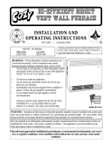
INCLUDED IN THE BOX
DIRECT VENT HEATER
(INSIDE WALL MOUNTING PLATE
AT
TACHED ON BACK)
INLET & OUTLET TUBES
INSTALLATION TEMPLATE
(TEMPLATE FOR HWDV080
ON REVERSE SIDE)
OUTSIDE WALL MOUNTING PLATE
& VENT CAP
VENT KIT
HARDWARE PACKET
VENT SHIELD
HEATER
HARDWARE PACKET

24632-0-0508Page 4
TOOLS NEEDED
SNIPS
5/16 NUT DRIVER
ADJUSTABLE WRENCH
CAULKING
PHILLIPS SCREW DRIVER
TAPE MEASURE
DRILL
SA
W
HARDWARE PACKETS
PLASTIC TOGGLE (6)
#10 X 1 ” SLOTTED HEX HEAD SCREW (6)½
NYLON WASHER (2)
#10 X ½” PHILLIPS HEX HEAD SCREW (3)
#10 X 2 ½” HEX HEAD SCREW (4)
HEATER
HARDWARE PACKET
VENT KIT
HARDWARE
PACKET

24632-0-0508 Page 5
GAS SPECIFICATIONS
MODEL FUEL MAXIMUM INPUT MINIMUM INPUT
HW080
Propane/LP -- Natural gas
8,000 Btu/hr 5,000 Btu/hr
HW181 18,000 Btu/hr
9,000 Btu/hr NAT
9,500 Btu/hr LP
MANIFOLD PRESSURE
Natural gas: 4" water column pressure
Propane/LP gas: 10.0" water column pressure
Gas Inlet 3/8"
SUPPLY
MINIMUM PRESSURE MAXIMUM PRESSURE
Natural Gas 5" W.C.P. 10.5" W.C.P.
LP Gas 11" W.C.P. 13" W.C.P.
Note: Appliance input ratings are based on sea level operation and need not be changed for operation up to 2,000 feet.
SPECIFICATIONS
MODELS HWDV080(B)DV HWDV181(B)DV
COMBUSTION
ATMOSPHERIC BURNER
STANDARD HEATING SPACE
85 - 250 Sq. Ft. 169 - 529 Sq. Ft.
EXTERNAL DIMENSIONS INCHES
HEIGHT 21 11/16" 25 3/16"
WIDTH 18 5/16" 22 5/16"
DEPTH 8 7/8" 9 3/8"
NET WEIGHT LBS.
33.5 45.5
MAX. GAS CONSUMPTION
8,000 Btu/hr. 18,000 Btu/hr.
SAFETY DEVICES
Safety valve (thermocouple)
Warning: This direct vent wall furnace is equipped for Natural or Propane gas. Field conversion is not permitted.
HIGH ALTITUDE SPECIFICATIONS
Model
0 - 2,000 feet (0 - 610 m) 2,000 - 4,500 feet (610 - 1 370 m)
Main Burner Orifice/Gas Pressure Main Burner Orifice/Gas Pressure
Natural Gas LP Gas Natural Gas LP Gas
HW080 #55 (4") #66 (10") #1.27 mm (4") #67 (10")
HW181 #49 (4") #56 (10") #50 (4") #57 (10")
For altitudes/elevations above 2,000 feet (610 m), input ratings should be reduced at the rate of 4% for each 1,000 feet (305 m) above
sea level. Canadian High Altitudes for locations having an elevation above mean sea level between 2,000 feet (609.9 m) and 4,500 feet
(1,370 m), use orifices as indicated in the following table:

24632-0-0508Page 6
UNIT DIMENSIONS
MAKE SURE THAT APPLIANCE IS SUITABLE FOR THE GAS SUPPLY AVAILABLE:
NATURAL GAS OR PROPANE/LP.

24632-0-0508 Page 7
IMPORTANT SAFETY INFORMATION
Children and adults should be alerted to the haz-
ards of high surface temperatures and should stay
away to avoid burns or clothing ignition.
Any safety screen or guard removed for servicing
must be replaced prior to operating the heater.
Do not use this heater if it has been under water.
Immediately call a qualified service technician to
inspect the heater and to replace any part of the
control system and any gas control which has been
under water.
Young children should be carefully supervised when
they are in the same room as the heater.
Installation and repair should be done by a quali-
fied service person. Heater should be inspected be-
fore use and at least annually by a qualified service
person.
More frequent cleaning may be required due to ex-
cessive lint from carpeting, bedding material etc. It
is imperative that control compartments, burners,
and circulating air passageways of the appliance be
kept clean.
Follow State and Local codes for installation.
DO NOT put anything around or on top of the fur-
nace that will obstruct the flow of combustion and
ventilation air.
DO keep the appliance area clear and free from
combustible material, gasoline and other flamma-
ble vapors and liquids.
DO examine venting system periodically and re-
place damaged parts.
DO make a periodic visual check of pilot and burn-
ers. Clean and replace damaged parts.
CAUTION: Pilot hole cover must be kept tightly
closed during operation.
Vent cap hot while furnace is in operation.

24632-0-0508Page 8
Some people cannot smell well. Some people cannot smell the
odor of the chemical put into the gas. You must find out if you
can smell the odorant in propane. Smoking can decrease your
ability to smell. Being around an odor for a time can affect your
sensitivity or ability to detect that odor. Sometimes other odors
in the area mask the gas odor. People may not smell the gas odor
or their minds are on something else. Thinking about smelling a
gas odor can make it easier to smell.
The odorant in LP-gas is colorless, and it can fade under some
circumstances. For example, if there is an underground leak, the
movement of the gas through soil can filter the odorant. Odorants
in LP-Gas also are subject to oxidation. This fading can occur if
there is rust inside the storage tank or in iron gas pipes.
The odorant in escaped gas can adsorb or absorb onto or into walls,
masonry and other materials and fabrics in a room. That will take
some of the odorant out of the gas, reducing its odor intensity.
LP-Gas may stratify in a closed area, and the odor intensity could
vary at different levels. Since it is heavier than air, there may be
more odor at lower levels. Always be sensitive to the slightest gas
odor. If you detect any odor, treat it as a serious leak. Immediately
go into action as instructed earlier.
Propane (LP-Gas) is a flammable gas which can cause fires
and explosions. In its natural state, propane is odorless and
colorless. You may not know all the following safety precautions
which can protect both you and your family from an accident.
Read them carefully now, then review them point by point
with the members of your household. Someday when there
may not be a minute to lose, everyone's safety will depend on
knowing exactly what to do. If, after reading the following
information, you feel you still need more information, please
contact your gas supplier.
• Do not operate electric switches, light matches, use your
phone. Do not do anything that could ignite the gas.
• Get everyone out of the building, vehicle, trailer, or area. Do
that IMMEDIATELY.
• Close all gas tank or cylinder supply valves.
• LP-Gas is heavier than air and may settle in low areas such
as basements. When you have reason to suspect a gas leak,
keep out of basements and other low areas. Stay out until
firefighters declare them to be safe.
• Use your neighbor's phone and call a trained LP-Gas service
person and the fire department. Even though you may not
continue to smell gas, do not turn on the gas again. Do not
re-enter the building, vehicle, trailer, or area.
• Finally, let the service man and firefighters check for escaped
gas. Have them air out the area before you return. Properly
trained LP-Gas service people should repair the leak, then
check and relight the gas appliance for you.
SOME POINTS TO REMEMBER
NO ODOR DETECTED - ODOR FADE
LP-GAS WARNING ODOR
If a gas leak happens, you should be able to smell the gas because of the odorant put in the LP-Gas.
That's your signal to go into immediate action!
• Learn to recognize the odor of LP-gas. Your local LP-Gas
Dealer can give you a "Scratch and Sniff" pamphlet. Use it
to find out what the propane odor smells like. If you suspect
that your LP-Gas has a weak or abnormal odor, call your
LP-Gas Dealer.
• If you are not qualified, do not light pilot lights, perform
service, or make adjustments to appliances on the LP-Gas
system. If you are qualified, consciously think about the odor
of LP-Gas prior to and while lighting pilot lights or perform
-
ing service or making adjustments.
• Sometimes a basement or a closed-up house has a musty
smell that can cover up the LP-Gas odor. Do not try to light
pilot lights, perform service, or make adjustments in an area
where the conditions are such that you may not detect the
odor if there has been a leak of LP-Gas.
• Odor fade, due to oxidation by rust or adsorption on walls
of new cylinders and tanks, is possible. Therefore, people
should be particularly alert and careful when new tanks or
cylinders are placed in service. Odor fade can occur in new
tanks, or reinstalled old tanks, if they are filled and allowed
to set too long before refilling. Cylinders and tanks which
have been out of service for a time may develop internal rust
which will cause odor fade. If such conditions are suspected
to exist, a periodic sniff test of the gas is advisable. If you
have any question about the gas odor, call your LP-gas dealer.
A periodic sniff test of the LP-gas is a good safety measure
under any condition.
• If, at any time, you do not smell the LP-Gas odorant and you
think you should, assume you have a leak. Then take the same
immediate action recommended above for the occasion when
you do detect the odorized LP-Gas.
• If you experience a complete "gas out," (the container is un
-
der no vapor pressure), turn the tank valve off immediately.
If the container valve is left on, the container may draw in
some air through openings such as pilot light orifices. If this
occurs, some new internal rusting could occur. If the valve is
left open, then treat the container as a new tank. Always be
sure your container is under vapor pressure by turning it off
at the container before it goes completely empty or having it
refilled before it is completely empty.
SAFETY INFORMATION FOR USERS OF LP-GAS

24632-0-0508 Page 9
Qualified Installing Agency
Installation and replacement of gas piping, gas utilization equip-
ment or accessories and repair and servicing of equipment shall
be performed by a qualified agency. The term “qualified agency”
means any individual, firm, corporation or company which either
in person or through a representative is engaged in and is respon-
sible for (1) the installation or replacement of gas piping or (2) the
connection, installation, repair or servicing of equipment, who is
experienced in such work, familiar with all precautions required
and has complied with all the requirements of the authority hav-
ing jurisdiction.
State of Massachusetts: The installation must be made by a
licensed plumber or gas fitter in the Commonwealth of Mas
-
sachusetts. The state of Massachusetts requires that a flexible
appliance connector cannot exceed three feet in length.
The installation must conform with local codes or, in the absence
of local codes, with the National Fuel Gas Code ANSI Z223.1/
NFPA 54* Natural Gas and Propane Installation Code, CSA
B149.1.
*Available from the American National Standards Institute, Inc., 11 West 42nd St.,
New York, N.Y. 10036.
The vent terminal of a direct vent appliance, with an input of
10,000 Btu per hour (3 kW) or less shall be located at least 6"
(150 mm) from any air opening into a building, and such an ap-
pliance with an input over 10,000 Btu per hour (3 kW) but not
over 50,000 Btu per hour (14.7 kW) shall be installed with a 9"
(229 mm) vent terminal clearance and the bottom of the vent ter-
minal and the air intake shall be located at least 12" (305 mm)
above grade.
WARNING: The nearest point of the vent cap should be a
minimum horizontal distance of six (6) feet (1.8 m) from
any pressure regulator. In case of regulator malfunction,
the six (6) feet (1.8 m) distance will reduce the chance of
gas entering the vent cap.
Always consult your local Building Department regarding regu
-
lations, codes or ordinances which apply to the installation of a
direct vent wall furnace.
Instructions to Installer
1. Installer must leave instruction manual with owner after instal-
lation.
2. Installer must have owner fill out and mail warranty card sup-
plied with furnace.
3. Installer should show owner how to start and operate furnace
and thermostat.
Warning:
Any change to this furnace or its control can be danger
-
ous. This is a heating appliance and any panel, door or
guard removed for servicing an appliance must be re-
placed prior to operating the appliance.
General Information
This furnace is design certified in accordance with American Na-
tional Standard/CSA Standard Z21.86 and CSA 2.32 by Under-
writers Laboratory as a direct vent wall furnace to be installed
according to these instructions.
Any alteration of the original design, installed other than as
shown in these instructions or use with a type of gas not shown
on the rating plate is the responsibility of the person and com
-
pany making the change.
Notice: During initial firing of this unit, its paint will bake out and
smoke will occur. To prevent triggering of smoke alarms, venti-
late the room in which the unit is installed.
Installation in Residential Garages
Gas utilization equipment in residential garages shall be installed
so that all burners and burner ignition devices are located not
less than 18" above the floor. Such equipment shall be located,
or protected, so it is not subject to physical damage by a moving
vehicle.
INTRODUCTION

24632-0-0508Page 10
REQUIREMENTS FOR MASSACHUSETTS
For all side wall horizontally vented gas fueled equipment installed
in every dwelling, building or structure used in whole or in part
for residential purposes, including those owned or operated by the
Commonwealth and where the side wall exhaust vent termination
is less than seven (7) feet above finished grade in the area of the
venting, including but not limited to decks and porches, the fol-
lowing requirements shall be satisfied:
1. INSTALLATION OF CARBON MONOXIDE DETECTORS.
At the time of installation of the side wall horizontal vented
gas fueled equipment, the installing plumber or gasfitter shall
observe that a hard wired carbon monoxide detector with an
alarm and battery back-up is installed on the floor level where
the gas equipment is to be installed. In addition, the installing
plumber or gasfitter shall observe that a battery operated or
hard wired carbon monoxide detector with an alarm is installed
on each additional level of the dwelling, building or structure
served by the side wall horizontal vented gas fueled equipment.
It shall be the responsibility of the property owner to secure the
services of qualified licensed professionals for the installation
of hard wired carbon monoxide detectors.
(a) In the event that the side wall horizontally vented gas
fueled equipment is installed in a crawl space or an attic,
the hard wired carbon monoxide detector with alarm and
battery back-up may be installed on the next adjacent floor
level.
(b) In the event that the requirements of this subdivision can
not be met at the time of completion of installation, the
owner shall have a period of thirty (30) days to comply
with the above requirements; provided, however, that dur
-
ing said thirty (30) day period, a battery operated carbon
monoxide detector with an alarm shall be installed.
2. APPROVED CARBON MONOXIDE DETECTORS. Each
carbon monoxide detector as required in accordance with the
above provisions shall comply with NFPA 720 and be ANSI/UL
2034 listed and IAS certified.
3. SIGNAGE. A metal or plastic identification plate shall be per
-
manently mounted to the exterior of the building at a minimum
height of eight (8) feet above grade directly in line with the
exhaust vent terminal for the horizontally vented gas fueled
heating appliance or equipment. The sign shall read, in print
size no less than one-half (1/2) inch in size, “GAS VENT
DIRECTLY BELOW. KEEP CLEAR OF ALL OBSTRUC-
TIONS”.
4. INSPECTION. The state or local gas inspector of the side wall
horizontally vented gas fueled equipment shall not approve
the installation unless, upon inspection, the inspector observes
carbon monoxide detectors and signage installed in accordance
with the provisions of 248 CMR 5.08(2)(a) 1 through 4.
(b) EXEMPTIONS: The following equipment is exempt from
248 CMR 5.08(2)(a)1 through 4:
1. The equipment listed in Chapter 10 entitled “Equip-
ment Not Required To Be Vented” in the most current
edition of NFPA 54 as adopted by the Board; and
2. Product Approved side wall horizontally vented gas
fueled equipment installed in a room or structure
separate from the dwelling, building or structure used
in whole or in part for residential purposes.
(c) MANUFACTURER REQUIREMENTS - GAS EQUIP
-
MENT VENTING SYSTEM PROVIDED. When the
manufacturer of Product Approved side wall horizontally
vented gas equipment provides a venting system design
or venting system components with the equipment, the
instructions provided by the manufacturer for installation
of the equipment and the venting system shall include:
1. Detailed instructions for the installation of the vent-
ing system design or the venting system components;
and
2. A complete parts list for the venting system design
or venting system.
(e) A copy of all installation instructions for all Product Ap
-
proved side wall horizontally vented gas fueled equipment,
all venting instructions, all parts lists for venting instruc-
tions, and/or all venting design instructions shall remain
with the appliance or equipment at the completion of the
installation.

24632-0-0508 Page 11
TERMINATION CLEARANCES
Description US Installations
1
A Clearance above grade, veranda, porch, deck, or balcony 12 inches (305 mm)
B Clearance to window or door that may be open
6 inches (152 mm) for appliance ≤ 10,000 Btuh (3 kW), 9 inches
(229 mm) for appliances > 10,000 Btuh (3 kW) and ≤ 50,000 Btuh
(15 kW), 12 inches (305 mm) for appliances > 50,000 Btuh (15 kW)
C Clearance to permanently closed window *
D Vertical clearance to ventilated soffit located above the
terminal within a horizontal distance of 2 feet (610 mm)
from the center line of the terminal
*
E Clearance to unventilated soffit *
F Clearance to outside corner 24"
G Clearance to inside corner 24"
H Clearance to each side of center line extended above me-
ter/regulator assembly
*
I Clearance to service regulator vent outlet *
J Clearance to non-mechanical air supply inlet to building
or the combustion air inlet to any other appliance.
6 inches (152 mm) for appliance ≤ 10,000 Btuh (3 kW), 9 inches
(229 mm) for appliances > 10,000 Btuh (3 kW) and ≤ 50,000 Btuh
(15 kW), 12 inches (305 mm) for appliances > 50,000 Btuh (15 kW)
K Clearance to a mechanical air supply inlet 3 feet (914 mm) above if within 10 feet (3.04 m) horizontally
L Clearance above paved sidewalk or paved driveway lo-
cated on public property
*
M Clearance under veranda, porch, deck, or balcony. *
The minimum distance from the center of the outside vent to the nearest inside and outside corner or obstruction or overhang is 24"
(457 mm).
1
In accordance with current ANSI Z223.1/NFPA 54, National Fuel Gas Code
*
For clearances not specified in ANSI Z223.1/NFPA 54
or CSA B149.1, one of the following shall be indicated:
a) A minimum clearance value determined by testing in accordance with section 2.19.6, or;
b) A reference to the following footnote:
“Clearance in accordance with local installation codes and the requirements of the gas supplier.”

24632-0-0508Page 12
Installing a New Main Gas Cock
Each appliance should have its own manual gas cock.
A manual main gas cock should be located in the vicinity of
the unit. Where none exists, or where its size or location is not
adequate, contact your local authorized installer for installation
or relocation.
Compounds used on threaded joints of gas piping shall be resistant
to the action of liquefied petroleum gases. The gas lines must be
checked for leaks by the installer. This should be done with a soap
solution watching for bubbles on all exposed connections, and if
unexposed, a pressure test should be made.
Never use an exposed flame to check for leaks. Appliance must be
disconnected from piping at inlet of control valve and pipe capped
or plugged for pressure test. Never pressure test with appliance
connected; control valve will sustain damage!
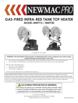
A gas valve and ground joint union should be installed in the gas
line upstream of the gas control to aid in servicing. It is required
by the National Fuel Gas Code that a drip line be installed near
the gas inlet. This should consist of a vertical length of pipe tee
connected into the gas line that is capped on the bottom in which
condensation and foreign particles may collect.
Method of Installing a Tee Fitting Sediment Trap
Figure 2
Locating Gas Supply
The gas line can enter the unit either through the floor or outside
wall. The gas line opening should be made at this time. Location
of the opening will be determined by the position of floor joists
and the valve and union used for servicing.
Note: Never use plastic pipe. Check to confirm whether your local
codes allow copper tubing or galvanized.
Note: Since some municipalities have additional local codes, it is
always best to consult your local authority and installation code.
The use of the following gas connectors is recommended:
— ANS Z21.24 Appliance Connectors of Corrugated Metal Tubing
and Fittings
— ANS Z21.45 Assembled Flexible Appliance Connectors of
Other Than All-Metal Construction
The above connectors may be used if acceptable by the authority
having jurisdiction. The state of Massachusetts requires that a
flexible appliance connector cannot exceed three feet in length.
Figure 1
Consult the current National Fuel Gas Code, ANSI Z223.1 CAN/
CGA-B149 (.1 or .2) installation code.
GAS SUPPLY
Recommended Gas Pipe Diameter
Pipe Length Schedule 40 Pipe
Inside Diameter
Tubing, Type L
Outside Diameter
Nat. L.P. Nat. L.P.
0-10 feet
0-3 meters
1/2”
12.7 mm
3/8”
9.5 mm
1/2”
12.7 mm
3/8”
9.5 mm
10-40 feet
4-12 meters
1/2”
12.7 mm
1/2”
12.7 mm
5/8”
15.9 mm
1/2”
12.7 mm
40-100 feet
13-30 meters
1/2”
12.7 mm
1/2”
12.7 mm
3/4”
19 mm
1/2”
12.7 mm
100-150 feet
31-46 meters
3/4”
19 mm
1/2”
12.7 mm
7/8”
22.2 mm
3/4”
19 mm
FLEXIBLE GAS LINE CONNECTION
RIGID GAS LINE CONNECTION
GAS SUPPLY
TEE HANDLE
FLEX TUBE
NPT NIPPLE
REGULATOR
VALVE
FLARE FITTING
FLARE SHUT OFF VALVE
CLOSE NIPPLE
TEE HANDLE
3/8 NIPPLE
REGULATOR
VALVE
NPT GAS SUPPLY
SHUT OFF VALVE
NPT UNION

24632-0-0508 Page 13
WARNING: The nearest point of the vent cap should be a
minimum horizontal distance of six (6) (1.83m) feet from
any pressure regulator. In case of regulator malfunction, the
six (6) foot (1.83m) distance will reduce the chance of gas
entering the vent cap.
CLEARANCES
GAS SUPPLY (continued)
Pressure Testing of the Gas Supply System
1. To check the inlet pressure to the gas valve, a 1/8" (3 mm) N.P.T.
plugged tapping, accessible for test gauge connection, must be
placed immediately upstream of the gas supply connection to
the appliance.
2. The appliance and its individual shutoff valve must be
disconnected from the gas supply piping system during any
pressure testing of that system at test pressures in excess of
1/2 psig (3.5 kPa).
3. The appliance must be isolated from the gas supply piping
system by closing its individual manual shutoff valve during
any pressure testing of the gas supply piping system at test
pressures equal to or less than 1/2 psig (3.5 kPa).
Attention! If one of the above procedures results in pressures in
excess of 1/2 psig (14" w.c.) (3.5 kPa) on the appliance gas valve,
it will result in a hazardous condition.
1. In selecting a location for installation, it is necessary to provide
adequate accessibility clearances for servicing and proper
installation.
2. Unit is supported by a wall bracket secured to the wall.
3. The minimum clearances from casing to combustible construction
is 36" (914.4 mm) on top, 6" (152 mm) on each side and
4" (102 mm) from the floor or from the top surface of carpeting,
tile or other floor covering and 0" (0 mm) to rear wall.
4. The minimum distance from the center of the vent cap to the
nearest outside corner or obstruction is 24" (610 mm).
5. The minimum wall depth is 4 1/2" (114.3 mm) and the
maximum is 12" (304.8 mm). The use of tubes not supplied
by the manufacturer results in unsatisfactory performance.
The vent terminal of a direct vent appliance, with an input of
50,000 (14.6 KW) BTU per hour or less shall be located at least 9"
(229 mm) from any opening through which flue gases could enter
a building. The bottom of the vent terminal and the air intake shall
be located at least 12" (305 mm) above grade.
The vent terminal of a direct vent appliance, with an input of
10,000 Btu per hour (3 kW) or less shall be located at least 6"
(150 mm) from any air opening into a building, and such an ap-
pliance with an input over 10,000 Btu per hour (3 kW) but not
over 50,000 Btu per hour (14.7 kW) shall be installed with a 9"
(229 mm) vent terminal clearance and the bottom of the vent ter-
minal and the air intake shall be located at least 12" (305 mm)
above grade.
Checking Manifold Pressure
Both Propane and Natural have a pressure regulator attached to
the gas valve. Natural gas models will have a manifold pressure
of approximately 4.0" w.c. (.996 kPa) at the valve outlet with
the inlet pressure to the valve from a minimum of 5.0" w.c.
(1.245 kPa) for the purpose of input adjustment to a maximum of
10.5" w.c. (2.61 kPa). Propane gas models will have a manifold
pressure approximately 10.0" w.c. (2.49 kPa) at the valve
outlet with the inlet pressure to the valve from a minimum of
11.0" w.c. (2.739 kPa) for the purpose of input adjustment to a
maximum of 13.0" w.c. (3.237 kPa).
A 1/8" (3 mm) N.P.T. plugged tapping, accessible for test gauge
connection, is located on the side of the gas pressure regulator.

24632-0-0508Page 14
INSTALLATION INSTRUCTIONS OVERVIEW
Figure 4 Figure 5 Figure 6
Location - All Models
Select a location near the center of the space to be heated. Overflow
heat will circulate through doorways into adjacent rooms.
The furnace is to be located on an outside wall. Locate wall studs
so that wall opening will be located between wall studs. One wall
stud can be used for attachment of inside wall plate. The wall
opening required as shown in Figure 3 is a minimum diameter of
6 1/4" (159 mm). The inside wall plate and the outside wall plate are
large enough to permit a wall opening diameter of 8" (203 mm).
A template is provided in furnace carton for positioning furnace
on the wall. Also, refer to Figure 3 for positioning the furnace on
wall and for locating gas line connection.
Figure 3
For large homes or spread-out floor plans, two or more furnaces
are recommended.
Do not locate furnace where a door could swing over the outer
casing, or where circulation could be retarded by furniture or
cabinets. See Figure 4.
Do not install in a closet, alcove or small hallway where the furnace
could be isolated by closing doors to the heated space. See Figures
5 and 6.
When location is selected, check the walls to make sure there are
no obstructions such as pipes, electric wiring, etc., which would
interfere with the installation of the furnace or vent pipe.
See Page 18, Box 4 for dimensions.

24632-0-0508 Page 15
1
Note: All references must be considered as if the observer is standing in front of the wall and/or appliance.
HEATER TO
BACK CASING
MOUNTING
SCREWS
WALL
MOUNTING TA
B
WALL
MOUNTING
SCREWS
WALL MOUNTING
PLA
TE
Mark the venting system hole location (as indicated on page
18) and the six holes through the wall mounting plate. Drill
accordingly. Insert the four wall anchors provided and tighten
the wall mounting plate firmly. Use special anchor fasteners if
the heater is to be installed on a wooden (hollow) wall. Line
up the two (2) tabs on the top of the wall mounting plate with
the holes in the back of the unit. Slide the back of the unit onto
the tabs of the wall mounting plate. Secure the back of the unit
into place using two (2) screws. Replace casing door. The heater
is now ready to receive the venting system assembly from the
opposite side of the wall.
Note: All references must be considered as if the observer is
standing in front of the wall and/or appliance.
IMPORTANT: The venting system must be properly
installed to insure proper and safe operation. The venting
system must also be properly re-installed and re-sealed to
insure proper and safe operation.
INSTALLATION AND ASSEMBLY
WARNING: Any change to this heater or its control can be dangerous. Provide adequate clearances and
accessibility for purposes of servicing and proper operation.
A manufactured home (USA only) installation must conform with the Manufactured Home Construction and Safety Standard, Title 24
CFR, Part 3280 or, when such standard is not applicable, the Standard for Manufactured Home Installations, ANSI Z225.1.
Due to high surface temperature, keep children, clothing, and furniture away. Keep burner and control compartments clean.
INSTALLATION OVERVIEW
WARNING: Improper installation, adjustments, alteration, service, or maintenance can cause property damage, personal injury
or loss of life.
Installation and service must be performed by a qualified installer, service agency, or the gas supplier.
These wall furnace models are designed for direct venting through a wall. Only venting components approved for these furnaces may
be used.
This unit is to be installed on a wall from 4 1/2" to 12" (114.3 mm to 304.8 mm) thick.

24632-0-0508Page 16
2
SILICON-BASED
SEALANT
MOUNTING
PLATE
CAP
FLUE OUTLET
TUBE
AIR INLET
TUBE
Failure to position these parts in accordance with diagram
or failure to use only parts specifically approved with these
appliances may result in property damage or personal
injury.
3
INSTALLATION OF HOUSEWARMER PRODUCT
INSTALLATION AND ANY REPAIRS TO THIS APPLIANCE MUST BE DONE BY A QUALIFIED
SERVICE PERSON.
WARNING: Read the installation instructions thoroughly before cutting or drilling any holes for
installation.
WARNING: Do not remove any rating plates attached to the unit.
CLEARANCES TO COMBUSTIBLES
Allow clearances (for all models) to adjacent combustible con
-
struction.
IMPORTANT: A qualified service person must install this ap
-
pliance. Installation must conform to local codes, or in the ab-
sence of local codes, with the latest edition of the National Fuel
Gas Code, ANSI Z223.1.
A qualified service person should be called to inspect this appliance annually.
Have all of your appliances checked annually.
INSTALLATION AND ASSEMBLY

24632-0-0508 Page 17
2
INTERIOR PREPARATION AND INSTALLATION OF THE BACK OF THE UNIT
Locate the wall mounting plate template included in your kit
and remove the perforated sections. Use painters tape to secure
the wall mounting plate template onto the interior wall where
the heater will be located. (Template for HWDV080 will be on
the opposite side of the shown template.)
MOUNTING TEMPLATE FOR
SEE OTHER SIDE FOR HWDV080
1
Before installing unit, remove wall mounting plate from back of unit.
3
Trace the template wall hole and (if applicable) the gas inlet hole onto the wall. Mark the six (6) wall mounting plate screw
holes onto the wall. The size of the gas inlet hole will depend upon the size of gas pipe coming into the unit. (See page 17,
box 2 and page 18, box 4).

24632-0-0508Page 18
5
MARKING FOR
WALL HOLE
MARKING FOR
WALL MOUNTING
PLATE HOLES
FLOOR LINE
MARKING FOR
GAS INLET HOLE
4
Remove the template from the wall after the holes are marked.
The hole location markings will be present on the wall.
Housewarmer recommends the use of the wall template to properly cut the wall holes and place the heater. If the template is
damaged or not included, refer to the table and graphic below for proper alignment of the wall holes and heater.. Be sure the
baseboard does not get in the way.
MEASUREMENTS
Model HWDV080(B)DV HWDV181(B)DV
C 7 3/8" 11 3/8"
D 10 7/8" 10 7/8"
E 21" 24 1/2"
F 9 1/4" 9 1/4"
G 4" 4"
I 6 1/4" 6 1/4"
INTERIOR PREPARATION AND INSTALLATION OF THE BACK OF THE UNIT

24632-0-0508 Page 19
6
7
9
Use a jigsaw to cut the holes out of the wall and discard the
inner circle debris. The wall is now prepared for the installation
of the unit.
Locate the studs in the wall and use at least four (4) wood screws
to attach the wall mounting plate to the wall.
If installing onto drywall (not into a stud), anchors must be
used.
Drill a pilot hole inside of the traced circle so that a jigsaw can
be used to cut the holes out.
Pilot
Hole
8
Pivot and remove casing door. Remove two screws from the
back inside of the unit and detach the wall mounting plate from
outside back of the unit.
INTERIOR PREPARATION AND INSTALLATION OF THE BACK OF THE UNIT

24632-0-0508Page 20
INTERIOR INSTALLATION OF THE FRONT OF THE UNIT
1
2
3
Line up the two (2) tabs on the top of the wall mounting plate
with the holes in the back of the unit. Slide the back of the unit
onto the tabs of the wall mounting plate.
After the back of the unit is attached to the wall, bring in the
gas line as shown on page 18, or follow the installation template
indications. Following your city, local and state codes, attach the
gas line to the unit.
NOTE: The gas line runs through the wall or floor of the
house..
GAS LINE
Secure the back of the unit into place using two (2) screws.
Replace casing door.
/