
6 416 m
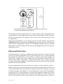
Mic Input Module
Mic Control Surface
Remote Control Interface
RCI
P/N 9310 1013 0001F rev. 2.00
© 2009 Aviom, Inc.
User Guide

i i
Trademarks
Aviom, A‑Net, the A‑Net icon, Pro16, Pro64, and Virtual Data Cable are
trademarks of Aviom, Inc.
All other trademarks are the property of their respective owners.
© 2009 Aviom, Inc. All rights reserved.
Information subject to change without notice.
Notice of Rights
All rights reserved. No part of this document may be reproduced or
transmitted in any form or by any means—electronic, mechanical, photocopy,
recording, or otherwise—without written permission of Aviom, Inc.
Certifications
ETL/cETL Listed
EMC: EN 55013, EN 55020, SAA AS/NZS 1053
Conforms to: IEC 60065, EN 60065, UL 6500‑2001
Certified to: CAN/CSA E60065, KETI
RoHS Status: Pb‑free
Pb
Pb-Free

i ii
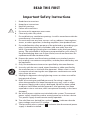
READ THIS FIRST
Important Safety Instructions
Read these instructions. 1.
Keep these instructions2.
Heed all warnings.3.
Follow all instructions.4.
Do not use this apparatus near water.5.
Clean only with a dry cloth.6.
Do not block any ventilation openings. Install in accordance with the 7.
manufacturer’s instructions.
Do not install near any heat sources such as radiators, heat registers, 8.
stoves, or other apparatus (including amplifiers) that produce heat.
Do not defeat the safety purpose of the polarized or grounding‑type 9.
plug. A polarized plug has two blades with one wider than the
other. A grounding type plug has two blades and a third grounding
prong. The wide blade or third prong are provided for your safety. If
the provided plug does not fit your outlet, consult an electrician for
replacement of the obsolete outlet.
Protect the power cord from being walked on or pinched, particu‑10.
larly at plugs, convenience receptacles, and the point where they exit
the apparatus.
Only use attachments/accessories specified by the manufacturer.11.
Use only with the cart, stand, tripod, bracket, or table specified by 12.
the manufacturer, or sold with the apparatus. When a cart is used,
use caution when moving the cart/apparatus combination to avoid
injury from tip‑over.
Unplug this apparatus during lightning storms or when unused for 13.
long periods of time.
Refer all servicing to qualified personnel. Servicing is required 14.
when the apparatus has been damaged in any way, such as when
the power‑supply cord or plug is damaged, liquid has been spilled
or objects have fallen into the apparatus, the apparatus has been
exposed to rain or moisture, does not operate normally, or has been
dropped.
No on/off power switches are included in the system. The external 15.
power supply should be used to control power to an Aviom device.
This power supply should remain readily operable.
The solid line over dashed line symbol (16. ) indicates that the
input voltage must be a DC voltage.
The box within a box symbol ( 17. ) indicates that the external power
supply is double insulated.
!

i v
TO REDUCE THE DANGER OF ELECTRICAL SHOCK DO NOT REMOVE COVERS.
NO USER SERVICEABLE PARTS INSIDE
REFER SERVICING TO QUALIFIED SERVICE PERSONNEL ONLY
To reduce the risk of fire or electrical shock, do not expose this
product to rain or other types of moisture.
To avoid the hazard of electrical shock, do not handle the
power cord with wet hands.
Replace fuse with same type and rating.
Operating Temperature: 10˚C to 50˚C (50˚F to 122˚F)
Risque de choc électrique – ne pas ouvrir. Pour réduire le risque de feu ou de choc
électrique, ne pas exposer cet équipement à la pluie ou la moisissure. Pour réduire
le risque de choc électrique, ne pas retirer le couvercle. Pièces non remplaçables
par l’utilisateur. Confier la réparation à une personne qualifiée. Attention – utiliser
seulement un fusible de rechange de même type.
Cet appareil est conforme à la section 15 de la norme FCC. Son fonctionnement est
soumis aux conditions suivantes : (1) cet équipement ne doit pas causer des interférences
nocives, et (2) cet équipement doit accepter toute interférence captée incluant les
interférences pouvant causer des opérations indésirables.
Cet appareil numérique de Classe B est conforme à la norme NMB‑003 du Canada.
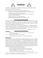
WARNING!
! !
CAUTION:
Using any audio system at high volume levels can cause permanent •
damage to your hearing.
Set your system volume as low as possible. •
Avoid prolonged exposure to excessive sound pressure levels.•
IMPORTANT:
This equipment has been tested and found to comply with the limits for a Class B digital
device, pursuant to part 15 of the FCC Rules. These limits are designed to provide reasonable
protection against harmful interference in a residential installation. This equipment
generates, uses and can radiate radio frequency energy and, if not installed and used in
accordance with the instructions, may cause harmful interference to radio communications.
However, there is no guarantee that interference will not occur in a particular installation. If
this equipment does cause harmful interference to radio or television reception, which can
be determined by turning the equipment off and on, the user is encouraged to try to correct
the interference by one or more of the following measures:
Reorient or relocate the receiving antenna.•
Increase the separation between the equipment and receiver.•
Connect the equipment into an outlet on a circuit different from •
that to which the receiver is connected.
Consult the dealer or an experienced radio/TV technician for help.•
Changes or modifications to the product not expressly approved by Aviom, Inc. could
void the user’s FCC authority to operate the equipment.

v
Aviom, Inc. Limited Warranty
Aviom, Inc. warrants this product against defects in materials and workmanship for a
period of one year from the date of the original retail purchase.
This warranty does not apply if the equipment has been damaged due to misuse,
abuse, accident, or problems with electrical power. The warranty also does not apply
if the product has been modified in any way, or if the product serial number has been
damaged, modified, or removed.
If a defect is discovered, first write or call Aviom, Inc. to obtain a Return Authorization
number. No service will be performed on any product returned without prior
authorization. Aviom, Inc. will, at its option, repair or replace the product at no charge
to you. The product must be returned during the warranty period, with transportation
charges prepaid to Aviom, Inc., 1157 Phoenixville Pike, Suite 201, West Chester, PA
19380. You must use the product’s original packing materials for shipment. Shipments
should be insured for the value of the product. Include your name, address, phone
number, description of the problem, and copy of the original bill of sale with the
shipment. The Return Authorization number should be written on the outside of the
box.
THIS LIMITED WARRANTY GIVES YOU SPECIFIC LEGAL RIGHTS. YOU MAY HAVE OTHER
RIGHTS, WHICH VARY FROM STATE TO STATE (OR JURISDICTION TO JURISDICTION).
AVIOM’S RESPONSIBILITY FOR MALFUNCTIONS AND DEFECTS IN HARDWARE IS
LIMITED TO REPAIR AND REPLACEMENT AS SET FORTH IN THIS LIMITED WARRANTY
STATEMENT. ALL EXPRESS AND IMPLIED WARRANTIES FOR THE PRODUCT, INCLUDING
BUT NOT LIMITED TO ANY IMPLIED WARRANTIES OF MERCHANTABILITY AND FITNESS
FOR A PARTICULAR PURPOSE, ARE LIMITED IN DURATION TO THE WARRANTY PERIOD
SET FORTH ABOVE. NO WARRANTIES, WHETHER EXPRESS OR IMPLIED, WILL APPLY
AFTER SUCH PERIOD.
AVIOM, INC. DOES NOT ACCEPT LIABILITY BEYOND THE REMEDIES SET FORTH IN THIS
LIMITED WARRANTY DOCUMENT. AVIOM, INC.’S LIABILITY IS LIMITED TO THE REPAIR
OR REPLACEMENT, AT OUR OPTION, OF ANY DEFECTIVE PRODUCT, AND SHALL IN NO
EVENT INCLUDE INCIDENTAL OR CONSEQUENTIAL DAMAGES OF ANY KIND.
SOME STATES DO NOT ALLOW EXCLUSIONS OR LIMITATION OF IMPLIED WARRANTIES
OR LIABILITY FOR INCIDENTAL OR CONSEQUENTIAL DAMAGES, SO THE ABOVE
LIMITATIONS MAY NOT APPLY TO YOU.

v i
Warranty Information
Please record the following information for future reference:
Your Authorized Aviom Dealer:
Name:
Address:
Phone:
Serial Numbers of Your Aviom Products:
Date of Purchase:
Your Authorized Aviom Dealer is your primary source for service and support.
The information recorded above will be helpful in communicating with your
Authorized Aviom Dealer should you need to contact Aviom Customer
Service. If you have any questions concerning the use of this unit, please
contact your Authorized Aviom Dealer first. For additional technical support,
or to find the name of the nearest Authorized Aviom Repair Station, check
the Aviom web site at www.aviom.com.
To fulfill warranty requirements, your Aviom product should be serviced
only at an authorized Aviom service center. The Aviom serial number label
must appear on the outside of the unit, or the Aviom warranty is void.
This manual and its contents are copyrighted by Aviom, Inc. All rights are
reserved by Aviom, Inc. This document may not, in whole or in part, be
copied, photocopied, reproduced, translated, or reduced to any electronic
medium or machine‑readable form without prior written consent from
Aviom, Inc.
The software and/or firmware contained within Aviom products is
copyrighted and all rights are reserved by Aviom, Inc.
Although every effort has been made to ensure the accuracy of the text
and illustrations in this manual, no guarantee is made or implied as to the
accuracy of the information contained within.

Table of Contents
Welcome . . . . . . . . . . . . . . . . . . . . . . . . . . . . . .1
Features . . . . . . . . . . . . . . . . . . . . . . . . . . .1
The EtherCon Connector . . . . . . . . . . . . . . . . . . .2
AC Power . . . . . . . . . . . . . . . . . . . . . . . . . . . . . . 3
AC Line Conditioning . . . . . . . . . . . . . . . . . . . . . . . 3
Rack Mounting. . . . . . . . . . . . . . . . . . . . . . . . . . .3
Transporting the 6416m in a Rack . . . . . . . . . . . . . . .4
Ventilation . . . . . . . . . . . . . . . . . . . . . . . . . . . . .4
Cleaning . . . . . . . . . . . . . . . . . . . . . . . . . . . . . .4
About A-Net . . . . . . . . . . . . . . . . . . . . . . . . . . . . 5
Clocking . . . . . . . . . . . . . . . . . . . . . . . . . . .5
Control Data . . . . . . . . . . . . . . . . . . . . . . . . .6
A‑Net Ports . . . . . . . . . . . . . . . . . . . . . . . . . .6
Support For Pro16 Series Products . . . . . . . . . . . . . . 7
Firmware Notice . . . . . . . . . . . . . . . . . . . . . . . . . .8
Pro64 Interface Conventions . . . . . . . . . . . . . . . . . . .9
Cat‑5e . . . . . . . . . . . . . . . . . . . . . . . . . . . . 9
Button Presses . . . . . . . . . . . . . . . . . . . . . . . . 9
Changing Values . . . . . . . . . . . . . . . . . . . . . . .9
Selecting Values . . . . . . . . . . . . . . . . . . . 10
DIP Switches . . . . . . . . . . . . . . . . . . . . . 10
Pro64 User Interface . . . . . . . . . . . . . . . . . . . . . . . 11
Basic Actions . . . . . . . . . . . . . . . . . . . . . . . . 11
A‑Net Slot . . . . . . . . . . . . . . . . . . . . . . . . . 12
Slots versus Channels. . . . . . . . . . . . . . . . . 12
Slots and Sample Rate . . . . . . . . . . . . . . . . 13
A‑Net Slot Example . . . . . . . . . . . . . . . . . . 16
Network Modes. . . . . . . . . . . . . . . . . . . . . . . 18
Auto Mode . . . . . . . . . . . . . . . . . . . . . . 18
Manual Mode . . . . . . . . . . . . . . . . . . . . 18
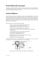
Pro64 Network Concepts . . . . . . . . . . . . . . . . . . . . 20
Control Master . . . . . . . . . . . . . . . . . . . . . . . . . 20
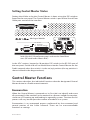
Setting Control Master Status . . . . . . . . . . . . . . . . 21
Control Master Functions . . . . . . . . . . . . . . . . . . 21
Enumeration . . . . . . . . . . . . . . . . . . . . . . . . 21
Adding Pro64 Modules to a Network . . . . . . . . . 22
Changing Settings . . . . . . . . . . . . . . . . . . . . . 22
Control Master and Clock Source . . . . . . . . . . . . . . 23
Clock Errors . . . . . . . . . . . . . . . . . . . . . 24
Network Sample Rate . . . . . . . . . . . . . . . . . . . . 24
Changing the Sample Rate . . . . . . . . . . . . . . 25
Auto/Manual Mode Selection . . . . . . . . . . . . . . . . 25
Changing the Network Mode . . . . . . . . . . . . . 26
Managed Mode. . . . . . . . . . . . . . . . . . . . . . . 26
v i i

Password Protection . . . . . . . . . . . . . . . . . . . . 27
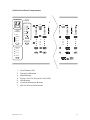
6416m Front Panel Components. . . . . . . . . . . . . . . . . 29
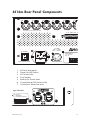
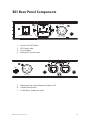
6416m Rear Panel Components . . . . . . . . . . . . . . . . . 32
6416m Network Settings . . . . . . . . . . . . . . . . . . . . 34
Control Master . . . . . . . . . . . . . . . . . . . . . . . 34
Control Master Errors . . . . . . . . . . . . . . . . . 34
A‑Net Slot Range Configuration . . . . . . . . . . . . . . . 35
Setting the A‑Net Slot Range . . . . . . . . . . . . . . . . 35
Network Mode . . . . . . . . . . . . . . . . . . . . . . . 36
A‑Net Transmit . . . . . . . . . . . . . . . . . . . . . . . 36
Changing the A‑Net Transmit Port . . . . . . . . . . 37
Clock Master . . . . . . . . . . . . . . . . . . . . . . . . 37
Sample Rate . . . . . . . . . . . . . . . . . . . . . . . . 37
Changing the Sample Rate . . . . . . . . . . . . . . 38
Sample Rates and A‑Net Slots. . . . . . . . . . . . . 39
6416m Front Panel Features . . . . . . . . . . . . . . . . . . . 40
A‑Net Slot Configuration . . . . . . . . . . . . . . . . . . 40
A‑Net Transmit . . . . . . . . . . . . . . . . . . . . . . . 40
Clock Master . . . . . . . . . . . . . . . . . . . . . . . . 41
Sample Rate . . . . . . . . . . . . . . . . . . . . . . . . 41
Function Button . . . . . . . . . . . . . . . . . . . . . . 41
Control Master LED . . . . . . . . . . . . . . . . . . . . . 41
VDC Slot and Port Configuration . . . . . . . . . . . . . . 42
Enter/Cancel Buttons . . . . . . . . . . . . . . . . . . . . 42
A‑Net LED . . . . . . . . . . . . . . . . . . . . . . . . . 42
Managed Button . . . . . . . . . . . . . . . . . . . . . . 43
Edit Lock Button . . . . . . . . . . . . . . . . . . . . . . 43
Query Functions (Get Info) . . . . . . . . . . . . . . 44
Control Group . . . . . . . . . . . . . . . . . . . . . . . 45
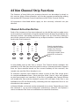
6416m Channel Strip Functions . . . . . . . . . . . . . . . . . 46
Channel Activation Button . . . . . . . . . . . . . . . . . 46
Channel Activation Rules . . . . . . . . . . . . . . . 47
Level Meter LEDs . . . . . . . . . . . . . . . . . . . . . . 47
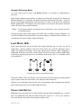
Stereo Link Button . . . . . . . . . . . . . . . . . . . . . 47
Mute Button . . . . . . . . . . . . . . . . . . . . . . . . 48
Edit Button . . . . . . . . . . . . . . . . . . . . . . . . . 49
Phase Button . . . . . . . . . . . . . . . . . . . . . . . . 49
Low Cut Button . . . . . . . . . . . . . . . . . . . . . . . 50
Pad Button . . . . . . . . . . . . . . . . . . . . . . . . . 50
+48V Phantom Power Button . . . . . . . . . . . . . . . . 51
Channel Gain . . . . . . . . . . . . . . . . . . . . . . . . 52
Gain Display . . . . . . . . . . . . . . . . . . . . . . . . 52
Control Group . . . . . . . . . . . . . . . . . . . . . . . 52
Mic Preamp Presets . . . . . . . . . . . . . . . . . . . . . . . 54
Save a Preset . . . . . . . . . . . . . . . . . . . . . . . . 54
v i ii

Recall a Preset . . . . . . . . . . . . . . . . . . . . . . . 55
Preset Rules. . . . . . . . . . . . . . . . . . . . . . . . . 55
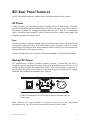
6416m Rear Panel Features . . . . . . . . . . . . . . . . . . . 56
AC Power . . . . . . . . . . . . . . . . . . . . . . . . . . 56
Fuse . . . . . . . . . . . . . . . . . . . . . . . . . 56
Backup DC Power . . . . . . . . . . . . . . . . . . . . . . 56
6416m DC Requirements . . . . . . . . . . . . . . . 56
A‑Net Ports . . . . . . . . . . . . . . . . . . . . . . . . . 57
Balanced Mic/Line Inputs . . . . . . . . . . . . . . . . . . 57
DB25 Audio Thru/Alternate In . . . . . . . . . . . . . . . . 58
Alternate Input . . . . . . . . . . . . . . . . . . . . 58
DB25 Pinout . . . . . . . . . . . . . . . . . . . . . 58
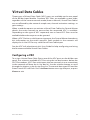
Virtual Data Cables . . . . . . . . . . . . . . . . . . . . . . . 60
Configuring a VDC . . . . . . . . . . . . . . . . . . . . . 60
GPIO . . . . . . . . . . . . . . . . . . . . . . . . . . . . 61
GPIO Configuration DIP Switches . . . . . . . . . . . 61
GPIO Terminal Blocks . . . . . . . . . . . . . . . . . 62
MIDI In, MIDI Out . . . . . . . . . . . . . . . . . . . . . . 62
RS‑232 Port . . . . . . . . . . . . . . . . . . . . . . . . . 62
RS‑232 Configuration DIP Switches . . . . . . . . . . 63
RS‑232 Baud Rates . . . . . . . . . . . . . . . . . . 63
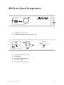
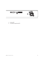
RCI Front Panel Components . . . . . . . . . . . . . . . . . . 66
RCI Rear Panel Components . . . . . . . . . . . . . . . . . . . 68
RCI Front Panel Features . . . . . . . . . . . . . . . . . . . . 69
Headphone Input Jack . . . . . . . . . . . . . . . . . . . 69
Monitor Volume Control . . . . . . . . . . . . . . . . . . 69
Network Mode Selection . . . . . . . . . . . . . . . . . . 69
A‑Net Slot . . . . . . . . . . . . . . . . . . . . . . . . . 70
Sync Indicator . . . . . . . . . . . . . . . . . . . . . . . 71
Control Group Selection . . . . . . . . . . . . . . . . . . 71
A‑Net LED . . . . . . . . . . . . . . . . . . . . . . . . . 71
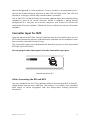
Controller Input for MCS . . . . . . . . . . . . . . . . . . 72
Cables Connecting the RCI and MCS . . . . . . . . . 72
RCI Rear Panel Features . . . . . . . . . . . . . . . . . . . . . 73
AC Power . . . . . . . . . . . . . . . . . . . . . . . . . . 73
Fuse . . . . . . . . . . . . . . . . . . . . . . . . . 73
Backup DC Power . . . . . . . . . . . . . . . . . . . . . . 73
Balanced Line‑Level Monitor Output . . . . . . . . . . . . 74
Output Pad Switch . . . . . . . . . . . . . . . . . . . . . 74
A‑Net Ports . . . . . . . . . . . . . . . . . . . . . . . . . 74
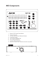
MCS Components . . . . . . . . . . . . . . . . . . . . . . . . 76
MCS Features . . . . . . . . . . . . . . . . . . . . . . . . . . 78
Channel Level Meters . . . . . . . . . . . . . . . . . . . 78
Numeric Keypad . . . . . . . . . . . . . . . . . . . . . . 78
Inc/Dec Selection Buttons. . . . . . . . . . . . . . . . . . 78
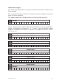
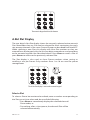
A‑Net Slot Display. . . . . . . . . . . . . . . . . . . . . . 79
Select a Slot . . . . . . . . . . . . . . . . . . . . . 79
i x

No Control Indicator . . . . . . . . . . . . . . . . . . . . 80
Save and Recall Buttons . . . . . . . . . . . . . . . . . . 80
Cancel and Enter Buttons . . . . . . . . . . . . . . . . . . 81
MCS Channel Strip . . . . . . . . . . . . . . . . . . . . . . . . 81
Gain Display . . . . . . . . . . . . . . . . . . . . . . . . 81
Gain Control . . . . . . . . . . . . . . . . . . . . . . . . 82
Mute Button . . . . . . . . . . . . . . . . . . . . . . . . 82
Phase Button . . . . . . . . . . . . . . . . . . . . . . . . 82
Low Cut Button . . . . . . . . . . . . . . . . . . . . . . . 83
+48V Phantom Power Button . . . . . . . . . . . . . . . . 84
Controller Connector . . . . . . . . . . . . . . . . . . . . 85
Cables Connecting the MCS and RCI . . . . . . . . . 85
Building a Pro64 Network . . . . . . . . . . . . . . . . . . . . 86
Choosing a Network Mode . . . . . . . . . . . . . . . . . 86
Connecting Pro64 Modules . . . . . . . . . . . . . . . . . 86
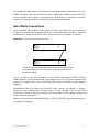
Basic Routing . . . . . . . . . . . . . . . . . . . . . . . . 86
Auto Mode Connections . . . . . . . . . . . . . . . . . . 87
Digital Copies in Auto Mode . . . . . . . . . . . . . 88
Adding a Merger Hub in Auto Mode . . . . . . . . . 89
Manual Mode Connections . . . . . . . . . . . . . . . . . 90
Digital Copies in Manual Mode . . . . . . . . . . . . 94
VDC Configuration . . . . . . . . . . . . . . . . . . . . . 97
VDC Slot Display . . . . . . . . . . . . . . . . . . . 97
VDC In Use LED . . . . . . . . . . . . . . . . . . 98
Assigning a VDC Slot . . . . . . . . . . . . . . . . . 99
Deactivate an Active VDC Slot . . . . . . . . . . . . 99
Advanced Functions . . . . . . . . . . . . . . . . . . . 100
Function Button . . . . . . . . . . . . . . . . . . . . . 100
Clear A‑Net Resources . . . . . . . . . . . . . . . .101
Mute/Unmute all Channels . . . . . . . . . . . . . .101
Password Lock . . . . . . . . . . . . . . . . . . . .101
Password Unlock . . . . . . . . . . . . . . . . . . 102
Set a New Password . . . . . . . . . . . . . . . . 102
Sample Alignment . . . . . . . . . . . . . . . . . . . . 103
Measure New Sample Alignment Value . . . . . . . 104
Use Stored Sample Alignment Value . . . . . . . . 104
Use Default Sample Alignment Value . . . . . . . . 105
Restore Factory Defaults . . . . . . . . . . . . . . 105
Firmware Update . . . . . . . . . . . . . . . . . . . . . 107
Update Connections . . . . . . . . . . . . . . . . 107
Firmware Update ‑ Local . . . . . . . . . . . . . . 107
Error Recovery . . . . . . . . . . . . . . . . . . . 108
Firmware Update ‑ via A‑Net . . . . . . . . . . . . 108
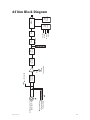
6416m Block Diagram . . . . . . . . . . . . . . . . . . . . . .110
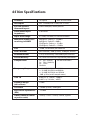
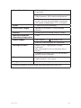
6416m Specifications . . . . . . . . . . . . . . . . . . . . . .111
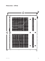
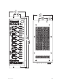
Dimensions ‑ 6416m . . . . . . . . . . . . . . . . . . . .113
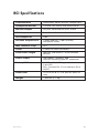
RCI Specifications . . . . . . . . . . . . . . . . . . . . . . . .115
x

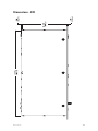
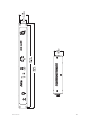
Dimensions ‑ RCI . . . . . . . . . . . . . . . . . . . . . .116
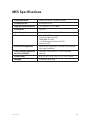
MCS Specifications. . . . . . . . . . . . . . . . . . . . . . . .118
Dimensions ‑ MCS . . . . . . . . . . . . . . . . . . . . .119
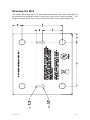
Mounting the MCS . . . . . . . . . . . . . . . . . . . . .121
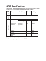
GPIO Specifications . . . . . . . . . . . . . . . . . . . . . . 122
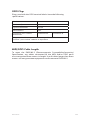
GPIO Plugs . . . . . . . . . . . . . . . . . . . . . 123
MIDI/GPIO Cable Lengths . . . . . . . . . . . . . . 123
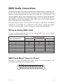
DB25 Audio Connections . . . . . . . . . . . . . . . . . . . .124
Wiring an Analog DB25 Cable . . . . . . . . . . . . . . . .124
DB25 Panel‑Mount Connector Pinout . . . . . . . . . . . .124
Using DB25 Jacks . . . . . . . . . . . . . . . . . . . . . 125
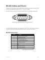
RS-232 Cables and Pinout . . . . . . . . . . . . . . . . . . . .126
RS‑232 Connections. . . . . . . . . . . . . . . . . . . . .126
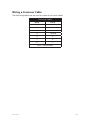
Wiring a Crossover Cable . . . . . . . . . . . . . . . . . .127
Warranty Registration . . . . . . . . . . . . . . . . . . . . . .135
x i

1Ab o u t Yo u r Pr o 64 Pr o d u c t
Welcome
Thank you for purchasing the 6416m Mic Input Module, RCI Remote Control
Interface, and MCS Mic Control Surface. All Pro64 products are powered by
A‑Net®, Aviom’s proprietary data transmission protocol designed especially
for the unique demands of live streaming audio.
In developing the Pro64 Series, we have made every effort to make the
user interface as easy to use and understand as possible. This User Guide
is designed to familiarize you with the features and functions of your new
Pro64® products. We encourage you to read the manual completely, as
some of the powerful features of your new product may not be immediately
apparent.
This combined User Guide covers the use and operation of the 6416m, RCI,
and MCS.
Features
All Pro64 Series products provide a host of professional features designed to
make A‑Net audio networking with Pro64 Series products easy to set up and
configure in a variety of professional audio situations.
6416m Mic Input Module Features:
Sixteen state‑of‑the‑art mic preamp channels
Remote controllable using the optional RCI Remote Control •
Interface and MCS Mic Control Surface
Support for • m‑control™ for Yamaha® digital consoles with
the 6416Y2 A‑Net Interface Card installed
XLR input jacks •
• DB25 Audio Thru/Alternate In connections
Mute, phase, low cut, +48V phantom power, and pad per •
channel
Link switches for stereo channel pairing•
Four Control Groups•
Individual A‑Net Slot activation buttons per channel•
Save and recall 16 preset configurations•
Virtual Data Cable™ connectivity for GPIO, MIDI, and RS‑232 •
Two A‑Net ports•
• EtherCon® RJ45 network connectors
Backup DC power connector •

2Ab o u t Yo u r Pr o 64 Pr o d u c t
RCI Remote Control Interface Features:
Any number of RCI modules can be installed in a Pro64 •
network
Four Control Groups •
Headphone monitor with level control •
Rear‑panel XLR line‑level output for monitoring selected •
mic preamp channel
Pad switch for XLR line‑level output•
Backup DC power connector •
MCS Mic Control Surface Features:
Full real‑time control of the selected channel’s gain, phase, •
mute, pad, +48V phantom power, and low cut filter
Real‑time metering of 64‑channel network stream•
Intuitive user interface with numeric keypad•
High resolution metering of selected channel•
Access to all Pro64 network audio resources•
Switchable peak hold•
Save and recall of 6416m presets•
Monitor up to 64 active Pro64 network channels •
simultaneously
Simple Cat‑5e connection to RCI •
Can be used simultaneously with • m‑control
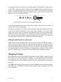
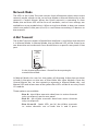
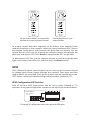
The EtherCon Connector
Pro64 Series products feature locking connectors for all network I/O. The
Neutrik® EtherCon connector is a dual RJ45‑type connector that can receive
a standard Category 5e cable or a cable fitted with the special locking
EtherCon connector.
When using a standard Cat‑5e cable, plug the cable into the center of the
EtherCon jack; release the cable by pressing on the small plastic tab built into
the cable connector.
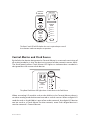
The locking EtherCon connector is similar to an XLR plug, the kind commonly
used on microphone cables. Insert an EtherCon‑equipped cable into the
jack until it clicks and locks in place. To remove the cable, press on the metal
release tab at the top of the panel‑mounted EtherCon jack and pull the
connector outward.

3MAi nt Ai ni n g Yo u r Pr o 64 Pr o d u c t
AC Power
Always plug the unit into a properly grounded (earthed) outlet. Always use
the AC line cord that was shipped with the unit. Grasp the power cable by the
connector and never by the cord itself when connecting and disconnecting
it from the power source.
Do not expose the Pro64 device to moisture, rain, or excessively damp
environments.
AC Line Conditioning
Aviom products are digital devices and as such are sensitive to sudden spikes
and drops in the AC line voltage. Changes in the line voltage from lightning,
power outages, etc., can sometimes damage electronic equipment.
To minimize the chance of damage to your equipment from sudden changes
in the AC line voltage, you may want to plug your equipment into a power
source that has surge and spike protection. Power outlet strips are available
with built‑in surge protection circuits that may help protect your equipment.
Other options for protection of your equipment include the use of an AC
line conditioner or a battery backup system (sometimes referred to as an
uninterruptible power supply, or UPS).
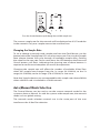
Rack Mounting
Pro64 products are designed to be mounted in a 19‑inch equipment rack.
The rack ears on each side of the device are designed to support the weight
of the product without additional hardware. Each rack ear contains holes for
two screws per side. Always support the unit with all four screws to avoid
damage to the unit.
To rack mount the Pro64 product, position it in the equipment rack at the
desired location. Use standard rack‑mounting screws (10‑32 size) to attach
the unit to your rack hardware. Tighten all four screws firmly, but avoid
overtightening.
Aviom suggests the use of non‑metallic washers between the rack‑mounting
screws and the device’s finished surface to avoid marring the finish on your
Aviom products.

4MAi nt Ai ni n g Yo u r Pr o 64 Pr o d u c t
Transporting the 6416m in a Rack
The 6416m Mic Input Module has attachment points for rear support
hardware built into the product’s sides. If the 6416m is to be rack mounted
and transported frequently, be sure to support the rear of the unit with
appropriate mounting hardware that matches the size of the rack used to
avoid damage to the product.
Ventilation
The 6416m is convection cooled and does not require a built‑in fan. Always
allow adequate ventilation for devices mounted in equipment racks. Avoid
placing your Pro64 product directly above or below other rack‑mounted
devices that produce high levels of heat, such as power amplifiers.
Do not block the side and back vented openings in the product’s case. The
openings in the top may be blocked as long as the temperature immediately
around the unit remains below 50°C. Although use in ambient temperatures
exceeding 50°C isn’t recommended, leaving an open rack space above the
unit will provide additional margin in extreme temperature conditions.
Cleaning
Before cleaning a Pro64 product, turn off the power switch and unplug the
unit from the AC power source.
To clean the surface of the Pro64 product use a clean, soft lint‑free cloth that
has been slightly moistened with water only. For tougher dirt, use a cloth
slightly dampened with water or with a mild detergent. Always be sure to dry
the surface of the unit before proceeding with use.
When cleaning your Aviom products, never spray cleaners directly onto the
product surfaces. Instead, spray a small amount of the cleaning solution onto
a clean cloth first. Then use the dampened cloth to clean the product.
Never use solvents or abrasive cleaners on the finished surfaces of your
Aviom products.

5Ab o u t A-ne t
About A-Net
Aviom’s A‑Net® is the only networking technology conceived, designed, and
optimized for managing and distributing audio using ordinary Cat‑5e cables
(or fiber by adding the MH10f Merger Hub). As implemented in the Pro64®
Series products, A‑Net can transmit up to 128 channels of uncompressed
24‑bit audio with the reliability and fidelity of analog, and the power and
flexibility of a true digital network.
Pro64 A‑Net allows variable sample rates in three ranges, from 44.1kHz±
to 192kHz±, with ultra‑low latency, jitter, and wander. Pro64 devices can
be connected in any combination of serial (daisy‑chain) or parallel (star)
topologies. Cable runs between Pro64 devices can be up to 400 feet (120
meters) on Cat‑5e
1
, and miles on fiber optics (with Aviom fiber‑capable
equipment).
Because A‑Net is designed specifically for audio, the technological limitations
of Ethernet and Ethernet‑based products are removed, while audio
performance and system flexibility are increased. A‑Net incorporates Aviom’s
unique patented and patent‑pending algorithms for controlling clock jitter
and wander, as well as system‑wide latency—regardless of an installation’s
size, design, or clocking setup. A‑Net offers significant advantages in fidelity,
performance, and flexibility over Ethernet‑based products.
A‑Net uses the “physical” layer of Ethernet, but it eliminates all the protocol
elements that are designed for computers and IT‑style networking. In
audio applications, these other layers reduce efficiency, impose system
restrictions, and introduce latency and timing instability. By eliminating
Ethernet data structures, A‑Net creates a superior network with enhanced
audio performance. With A‑Net and the Pro64 Series, Aviom continues to
break new ground in the design and development of innovative digital audio
networking technologies and solutions.
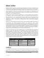
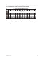
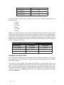
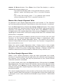
Pro64 Series Supported Sample Rates
Sample Rate Minimum Maximum
1x 44.1/48kHz 39.7kHz 52kHz
2x 88.2/96kHz 79.4kHz 104kHz
4x 176.4/192kHz 158.8kHz 208kHz
Clocking
The Pro64 network offers the most flexible clocking and synchronization
options in the industry. Pro64 devices support three ranges of variable sample
1 Cat-5e, Cat-6, or better, Unshielded Twisted Pair (UTP) cable

6Ab o u t A-ne t
rates, from 44.1/48kHz± to 192kHz±. Because no sample rate converters are
used, audio transmission is kept fast and clean, eliminating the audio artifacts
and signal degradation inherent to sample rate conversion—even when
syncing to an external clock source.
Any Pro64 I/O module can be designated the Clock Master for the network,
generating and distributing its internal clock. Digital I/O modules are capable
of syncing to and distributing an external clock from a Word Clock or AES3
source to the network.
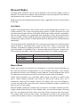
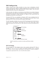
Control Data
The Pro64 Series has built‑in, dedicated bandwidth for 14 channels of
non‑audio control data through the use of Aviom’s innovative Virtual Data
Cables™. These data streams are always available to carry MIDI, RS‑232, RS‑
422, or GPIO (General Purpose I/O), and they never compete with the audio
channels for network resources, regardless of the system configuration. (Not
all VDC™ data types are supported on every Pro64 module.)
Because VDC inputs are simply incorporated into the A‑Net stream, these
control signals can be transmitted over very long cable runs and even across
an entire Pro64 network, significantly expanding the applications possible
with MIDI, RS‑232/422, and GPIO. And as with audio signals, VDC control data
can be input anywhere and output anywhere else in the network.
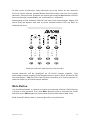
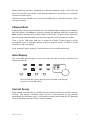
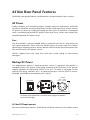
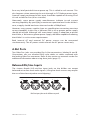
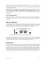
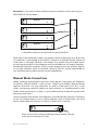
A-Net Ports
Pro64 I/O modules have dual A‑Net ports, labeled A and B. Both ports carry
a bidirectional A‑Net stream at all times. (That is, both ports are always
transmitting and receiving A‑Net data.) Pro64 networks can be configured in
one of two operational modes, Auto Mode or Manual Mode, depending on
the requirements of a particular system.
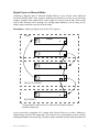
In Auto Mode, there are no connection rules; connect a Cat‑5e cable to either
the A or B port and the system does the rest. Auto Mode provides a true
audio network with 64 available “Slots” for transporting audio (at 44.1/48kHz).
Every audio Slot is available everywhere in the system, with no upstream/
downstream restrictions.
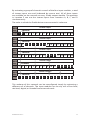
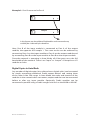
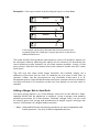
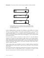
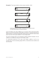
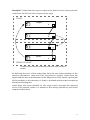
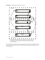
In Manual Mode, the Pro64 network becomes a 64x64 system (at 48kHz),
similar to a traditional stage‑to‑FOH snake. At every point in the Manual
Mode network, two 64‑channel streams are available on the cable and in
each module. The configuration of the cables and ports has an impact on
the makeup of the network and the distribution of audio signals. The user
can direct A‑Net data from an input module to a specific port (A, B, or both).
Output modules can be configured to output audio signals received from a
specific A‑Net port (A or B).

7Ab o u t A-ne t
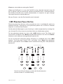
Support For Pro16 Series Products
Pro64 Series products can be combined with Pro16™ Series output products
such as the Pro16 Monitor Mixing System by adding the Pro64 ASI A‑Net
Systems Interface. This 1U module converts Pro64 data to Pro16 data,
providing up to four streams of 16‑channel data (depending on the Pro64
sample rate) that can be used with A‑16II and A‑16R Personal Mixers, A‑Net
Distributors, and AN‑16/o Output Modules.
The ASI is not compatible with the A‑Net output of Pro16 input modules such
as the AN‑16/i, AN‑16/i‑M, the Y1 console interface card (for Yamaha® digital
products), and A‑Net console cards built by third‑party manufacturers for
their digital console products.

4Fi r M w A r e no t i c e
Firmware Notice
All Pro64 devices in a network should be updated to use the most recent
rmware version to ensure trouble-free operation.
As new Pro64 modules are released, older Pro64 products need to be
updated so that they recognize the features and functions of the newer
modules—something that is especially important if one of the older devices
will be used as the network’s Control Master. (If for some reason you cannot
update the firmware on older Pro64 devices before using them, set the
newest module to be the network Control Master.)
Pro64 Update Tool is a free Windows software application for updating the
operating firmware in Pro64 Series products.
The Pro64 Update Tool requires a direct RS‑232 (serial) connection between
the computer and the Control Master device on the Pro64 network. Normally
this is accomplished by connecting a null modem DB9 cable between the
RS‑232 jack on the computer and the Pro64 device. Complete information on
using RS‑232 (and USB‑to‑RS‑232 adapters) is available on the Aviom website.
Updates take just a few minutes per module.
Pro64 Update Tool is designed to run on a PC under Microsoft® Windows® XP.
It has also been tested and found to be compatible with Microsoft Windows
Vista®. Mac users can run Pro64 Update Tool using Windows XP running
under Apple’s Boot Camp program on Intel‑based Macs.
Get the Pro64 Update Tool and firmware update files from the Aviom website:
http://www.aviom.com

9Pr o 64 in t e r F A c e co n v e n t i o n s
Pro64 Interface Conventions
Many Pro64 Series products have similar user interface components,
including buttons, LEDs, and switches. When describing the features and
functions of Pro64 Series products, the following conventions will be used.
Cat-5e
All Cat‑5e connections between A‑Net devices should use Unshielded
Twisted Pair (UTP) cable. The cable can be of the stranded or solid type; solid
wire performs better over long distances, while stranded wire is more flexible
and easier to manipulate and therefore easier to work with in a performance
situation where short cables are required.
Cables designated as Cat‑5e in Pro64 documentation can be interchanged
with any Cat‑6 (or better) cable. Cables will be referred to simply as “Cat‑5e.”
Connectors on Cat‑5e cables can be of the standard RJ45 variety or locking
Neutrik EtherCon type.
Button Presses
When referring to specific front‑panel labels, LEDs, and buttons, or when
describing a Pro64 function that requires the press of a button on the front
panel of a device, a special typeface will be used. For example, “Press the
En t E r button to confirm the sample rate change.”
Buttons that work in combination, giving the user a choice when performing
an operation, will be referred to as one unit. For example, “Changing the
sample rate requires the user to confirm the change using the Enter/Cancel
buttons.“
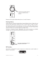
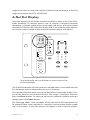
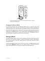
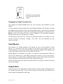
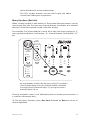
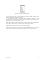
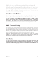
Changing Values
When editing values on the front panel of a Pro64 device, some operations
will require the use of the inc/dec buttons (short for increment/decrement) .
These buttons scroll up and down through a list of available values. Holding
the button down does not accelerate scrolling. The front panel of a Pro64
module is marked only with indicator arrows.
Page is loading ...
Page is loading ...
Page is loading ...
Page is loading ...
Page is loading ...
Page is loading ...
Page is loading ...
Page is loading ...
Page is loading ...
Page is loading ...
Page is loading ...
Page is loading ...
Page is loading ...
Page is loading ...
Page is loading ...
Page is loading ...
Page is loading ...
Page is loading ...
Page is loading ...
Page is loading ...
Page is loading ...
Page is loading ...
Page is loading ...
Page is loading ...
Page is loading ...
Page is loading ...
Page is loading ...
Page is loading ...
Page is loading ...
Page is loading ...
Page is loading ...
Page is loading ...
Page is loading ...
Page is loading ...
Page is loading ...
Page is loading ...
Page is loading ...
Page is loading ...
Page is loading ...
Page is loading ...
Page is loading ...
Page is loading ...
Page is loading ...
Page is loading ...
Page is loading ...
Page is loading ...
Page is loading ...
Page is loading ...
Page is loading ...
Page is loading ...
Page is loading ...
Page is loading ...
Page is loading ...
Page is loading ...
Page is loading ...
Page is loading ...
Page is loading ...
Page is loading ...
Page is loading ...
Page is loading ...
Page is loading ...
Page is loading ...
Page is loading ...
Page is loading ...
Page is loading ...
Page is loading ...
Page is loading ...
Page is loading ...
Page is loading ...
Page is loading ...
Page is loading ...
Page is loading ...
Page is loading ...
Page is loading ...
Page is loading ...
Page is loading ...
Page is loading ...
Page is loading ...
Page is loading ...
Page is loading ...
Page is loading ...
Page is loading ...
Page is loading ...
Page is loading ...
Page is loading ...
Page is loading ...
Page is loading ...
Page is loading ...
Page is loading ...
Page is loading ...
Page is loading ...
Page is loading ...
Page is loading ...
Page is loading ...
Page is loading ...
Page is loading ...
Page is loading ...
Page is loading ...
Page is loading ...
Page is loading ...
Page is loading ...
Page is loading ...
Page is loading ...
Page is loading ...
Page is loading ...
Page is loading ...
Page is loading ...
Page is loading ...
Page is loading ...
Page is loading ...
Page is loading ...
Page is loading ...
Page is loading ...
Page is loading ...
Page is loading ...
Page is loading ...
Page is loading ...
Page is loading ...
Page is loading ...
Page is loading ...
Page is loading ...
Page is loading ...
Page is loading ...
Page is loading ...
Page is loading ...
Page is loading ...
Page is loading ...
-
 1
1
-
 2
2
-
 3
3
-
 4
4
-
 5
5
-
 6
6
-
 7
7
-
 8
8
-
 9
9
-
 10
10
-
 11
11
-
 12
12
-
 13
13
-
 14
14
-
 15
15
-
 16
16
-
 17
17
-
 18
18
-
 19
19
-
 20
20
-
 21
21
-
 22
22
-
 23
23
-
 24
24
-
 25
25
-
 26
26
-
 27
27
-
 28
28
-
 29
29
-
 30
30
-
 31
31
-
 32
32
-
 33
33
-
 34
34
-
 35
35
-
 36
36
-
 37
37
-
 38
38
-
 39
39
-
 40
40
-
 41
41
-
 42
42
-
 43
43
-
 44
44
-
 45
45
-
 46
46
-
 47
47
-
 48
48
-
 49
49
-
 50
50
-
 51
51
-
 52
52
-
 53
53
-
 54
54
-
 55
55
-
 56
56
-
 57
57
-
 58
58
-
 59
59
-
 60
60
-
 61
61
-
 62
62
-
 63
63
-
 64
64
-
 65
65
-
 66
66
-
 67
67
-
 68
68
-
 69
69
-
 70
70
-
 71
71
-
 72
72
-
 73
73
-
 74
74
-
 75
75
-
 76
76
-
 77
77
-
 78
78
-
 79
79
-
 80
80
-
 81
81
-
 82
82
-
 83
83
-
 84
84
-
 85
85
-
 86
86
-
 87
87
-
 88
88
-
 89
89
-
 90
90
-
 91
91
-
 92
92
-
 93
93
-
 94
94
-
 95
95
-
 96
96
-
 97
97
-
 98
98
-
 99
99
-
 100
100
-
 101
101
-
 102
102
-
 103
103
-
 104
104
-
 105
105
-
 106
106
-
 107
107
-
 108
108
-
 109
109
-
 110
110
-
 111
111
-
 112
112
-
 113
113
-
 114
114
-
 115
115
-
 116
116
-
 117
117
-
 118
118
-
 119
119
-
 120
120
-
 121
121
-
 122
122
-
 123
123
-
 124
124
-
 125
125
-
 126
126
-
 127
127
-
 128
128
-
 129
129
-
 130
130
-
 131
131
-
 132
132
-
 133
133
-
 134
134
-
 135
135
-
 136
136
-
 137
137
-
 138
138
-
 139
139
-
 140
140
-
 141
141
-
 142
142
-
 143
143
-
 144
144
-
 145
145
-
 146
146
-
 147
147


Ask a question and I''ll find the answer in the document
Finding information in a document is now easier with AI
Related papers
Other documents
-
Tascam IF-AV/DM Product information
-
 E-Mu Tracker Pre Supplementary Manual
-
Yale Value Safes User manual
-
 Midi Solutions MultiVoltage Professional Series Operating instructions
-
Dwyer Series MCS User manual
-
 Buildbotics CNC Controller Quick start guide
-
Broadcast Devices AES-408 Technical Reference Manual
-
ALLEN & HEATH Me-U User manual
-
ALLEN & HEATH ME-1 User manual
-
Peavey MPE-S2 MA Series Mic Pre-Amp Module Owner's manual


