Lincoln Electric 305D User manual
- Category
- Welding System
- Type
- User manual

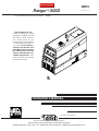
Ranger
P
305D
$%')$'W(V"#*!
"
December, 2010
(165DI5@5>4C?>.?E
Lincoln arc welding and cutting
equipment is designed and built
with safety in mind. However,
your overall safety can be
increased by proper installation
... and thoughtful operation on
your part. $ #$) #()!!
$%')$' '%' )(
&*%"#),)$*) '
# )( "#*! # )
(). %'*)$#( $#
)# )'$*$*) And,
most importantly, think before
you act and be careful.
For use with machines having Code Numbers:
• Sales and Service through Subsidiaries and Distributors Worldwide •
Cleveland, Ohio 44117-1199 U.S.A. TEL: 216.481.8100 FAX: 216.486.1751 WEB SITE: www.lincolnelectric.com
• World's Leader in Welding and Cutting Products •
Copyright © Lincoln Global Inc.
RETURN TO MAIN MENU

$'##
@?G5B545AE9@=5>D
1.a. Turn the engine off before troubleshooting and maintenance
work unless the maintenance work requires it to be running.
____________________________________________________
1.b. Operate engines in open, well-ventilated
areas or vent the engine exhaust fumes
outdoors.
____________________________________________________
1.c. Do not add the fuel near an open flame
welding arc or when the engine is running.
Stop the engine and allow it to cool before
refueling to prevent spilled fuel from vaporiz-
ing on contact with hot engine parts and
igniting. Do not spill fuel when filling tank. If
fuel is spilled, wipe it up and do not start
engine until fumes have been eliminated.
____________________________________________________
1.d. Keep all equipment safety guards, covers and devices in
position and in good repair.Keep hands, hair, clothing and
tools away from V-belts, gears, fans and all other moving
parts when starting, operating or repairing equipment.
____________________________________________________
1.e. In some cases it may be necessary to remove safety
guards to perform required maintenance. Remove
guards only when necessary and replace them when the
maintenance requiring their removal is complete.
Always use the greatest care when working near moving
parts.
___________________________________________________
1.f. Do not put your hands near the engine fan.
Do not attempt to override the governor or
idler by pushing on the throttle control rods
while the engine is running.
___________________________________________________
1.g. To prevent accidentally starting gasoline engines while
turning the engine or welding generator during maintenance
work, disconnect the spark plug wires, distributor cap or
magneto wire as appropriate.
9
().
9
',!##/'$*( %'$)).$*'(!#$)'('$"%$((!('$*(#*'.$')
%!'#,.%" ',''(($*!$#(*!),))'$)$'$'$%')#
Read and understand the following safety highlights. For additional safety information, it is strongly recommended that you
purchase a copy of “Safety in Welding & Cutting - ANSI Standard Z49.1” from the American Welding Society, P.O. Box
351040, Miami, Florida 33135 or CSA Standard W117.2-1974. A Free copy of “Arc Welding Safety” booklet E205 is available
from the Lincoln Electric Company, 22801 St. Clair Avenue, Cleveland, Ohio 44117-1199.
(*')) !! #()!!)$#$%')$#"#)## # '%' %'$*'( '
%'$'"$#!..&*!#+*!(
,'##
!)'#
"#)!(
=1I2541>75B?EC
2.a. Electric current flowing through any conductor causes
localized Electric and Magnetic Fields (EMF). Welding
current creates EMF fields around welding cables and
welding machines
2.b. EMF fields may interfere with some pacemakers, and
welders having a pacemaker should consult their physician
before welding.
2.c. Exposure to EMF fields in welding may have other health
effects which are now not known.
2.d. All welders should use the following procedures in order to
minimize exposure to EMF fields from the welding circuit:
2.d.1.
Route the electrode and work cables together - Secure
them with tape when possible.
2.d.2. Never coil the electrode lead around your body.
2.d.3. Do not place your body between the electrode and
work cables. If the electrode cable is on your right
side, the work cable should also be on your right side.
2.d.4. Connect the work cable to the workpiece as close as
possible to the area being welded.
2.d.5. Do not work next to welding power source.
1.h. To avoid scalding, do not remove the
radiator pressure cap when the engine is
hot.
!$'#%'$%$()$#,'##(
Diesel engine exhaust and some of its constituents
are known to the State of California to cause can-
cer, birth defects, and other reproductive harm.
The engine exhaust from this product contains
chemicals known to the State of California to cause
cancer, birth defects, or other reproductive harm.
The Above For Diesel Engines
The Above For Gasoline Engines

99
99
().
ARC RAYS can burn.
4.a. Use a shield with the proper filter and cover
plates to protect your eyes from sparks and
the rays of the arc when welding or observing
open arc welding. Headshield and filter lens
should conform to ANSI Z87. I standards.
4.b. Use suitable clothing made from durable flame-resistant
material to protect your skin and that of your helpers from
the arc rays.
4.c. Protect other nearby personnel with suitable, non-flammable
screening and/or warn them not to watch the arc nor expose
themselves to the arc rays or to hot spatter or metal.
ELECTRIC SHOCK can
kill.
3.a. The electrode and work (or ground) circuits
are electrically “hot” when the welder is on.
Do not touch these “hot” parts with your bare
skin or wet clothing. Wear dry, hole-free
gloves to insulate hands.
3.b. Insulate yourself from work and ground using dry insulation.
Make certain the insulation is large enough to cover your full
area of physical contact with work and ground.
In addition to the normal safety precautions, if welding
must be performed under electrically hazardous
conditions (in damp locations or while wearing wet
clothing; on metal structures such as floors, gratings or
scaffolds; when in cramped positions such as sitting,
kneeling or lying, if there is a high risk of unavoidable or
accidental contact with the workpiece or ground) use
the following equipment:
• Semiautomatic DC Constant Voltage (Wire) Welder.
• DC Manual (Stick) Welder.
• AC Welder with Reduced Voltage Control.
3.c. In semiautomatic or automatic wire welding, the electrode,
electrode reel, welding head, nozzle or semiautomatic
welding gun are also electrically “hot”.
3.d. Always be sure the work cable makes a good electrical
connection with the metal being welded. The connection
should be as close as possible to the area being welded.
3.e. Ground the work or metal to be welded to a good electrical
(earth) ground.
3.f.
Maintain the electrode holder, work clamp, welding cable and
welding machine in good, safe operating condition. Replace
damaged insulation.
3.g. Never dip the electrode in water for cooling.
3.h. Never simultaneously touch electrically “hot” parts of
electrode holders connected to two welders because voltage
between the two can be the total of the open circuit voltage
of both welders.
3.i. When working above floor level, use a safety belt to protect
yourself from a fall should you get a shock.
3.j. Also see Items 6.c. and 8.
FUMES AND GASES
can be dangerous.
5.a. Welding may produce fumes and gases
hazardous to health. Avoid breathing these
fumes and gases. When welding, keep
your head out of the fume. Use enough
ventilation and/or exhaust at the arc to keep
fumes and gases away from the breathing zone. When
welding with electrodes which require special
ventilation such as stainless or hard facing (see
instructions on container or MSDS) or on lead or
cadmium plated steel and other metals or coatings
which produce highly toxic fumes, keep exposure as
low as possible and within applicable OSHA PEL and
ACGIH TLV limits using local exhaust or mechanical
ventilation. In confined spaces or in some circum-
stances, outdoors, a respirator may be required.
Additional precautions are also required when welding
on galvanized steel.
5. b. The operation of welding fume control equipment is affected
by various factors including proper use and positioning of
the equipment, maintenance of the equipment and the spe-
cific welding procedure and application involved. Worker
exposure level should be checked upon installation and
periodically thereafter to be certain it is within applicable
OSHA PEL and ACGIH TLV limits.
5.c.
Do not weld in locations near chlorinated hydrocarbon
vapors
coming from degreasing, cleaning or spraying operations.
The heat and rays of the arc can react with solvent vapors
to
form phosgene, a highly toxic gas, and other irritating prod-
ucts.
5.d. Shielding gases used for arc welding can displace air and
cause injury or death. Always use enough ventilation,
especially in confined areas, to insure breathing air is safe.
5.e. Read and understand the manufacturer’s instructions for this
equipment and the consumables to be used, including the
material safety data sheet (MSDS) and follow your
employer’s safety practices. MSDS forms are available from
your welding distributor or from the manufacturer.
5.f. Also see item 1.b.

999
().
999
FOR ELECTRICALLY
powered equipment.
8.a. Turn off input power using the disconnect
switch at the fuse box before working on
the equipment.
8.b. Install equipment in accordance with the U.S. National
Electrical Code, all local codes and the manufacturer’s
recommendations.
8.c. Ground the equipment in accordance with the U.S. National
Electrical Code and the manufacturer’s recommendations.
CYLINDER may explode
if damaged.
7.a. Use only compressed gas cylinders
containing the correct shielding gas for the
process used and properly operating
regulators designed for the gas and
pressure used. All hoses, fittings, etc. should be suitable for
the application and maintained in good condition.
7.b. Always keep cylinders in an upright position securely
chained to an undercarriage or fixed support.
7.c. Cylinders should be located:
• Away from areas where they may be struck or subjected to
physical damage.
• A safe distance from arc welding or cutting operations and
any other source of heat, sparks, or flame.
7.d. Never allow the electrode, electrode holder or any other
electrically “hot” parts to touch a cylinder.
7.e. Keep your head and face away from the cylinder valve outlet
when opening the cylinder valve.
7.f. Valve protection caps should always be in place and hand
tight except when the cylinder is in use or connected for
use.
7.g. Read and follow the instructions on compressed gas
cylinders, associated equipment, and CGA publication P-l,
“Precautions for Safe Handling of Compressed Gases in
Cylinders,” available from the Compressed Gas Association
1235 Jefferson Davis Highway, Arlington, VA 22202.
WELDING and CUTTING
SPARKS can
cause fire or explosion.
6.a.
Remove fire hazards from the welding area.
If this is not possible, cover them to prevent
the welding sparks from starting a fire.
Remember that welding sparks and hot
materials from welding can easily go through small cracks
and openings to adjacent areas. Avoid welding near
hydraulic lines. Have a fire extinguisher readily available.
6.b. Where compressed gases are to be used at the job site,
special precautions should be used to prevent hazardous
situations. Refer to “Safety in Welding and Cutting” (ANSI
Standard Z49.1) and the operating information for the
equipment being used.
6.c. When not welding, make certain no part of the electrode
circuit is touching the work or ground. Accidental contact
can cause overheating and create a fire hazard.
6.d. Do not heat, cut or weld tanks, drums or containers until the
proper steps have been taken to insure that such procedures
will not cause flammable or toxic vapors from substances
inside. They can cause an explosion even
though
they have
been “cleaned”. For information, purchase “Recommended
Safe Practices for the
Preparation
for Welding and Cutting of
Containers and Piping That Have Held Hazardous
Substances”, AWS F4.1 from the American Welding Society
(see address above).
6.e. Vent hollow castings or containers before heating, cutting or
welding. They may explode.
6.f.
Sparks and spatter are thrown from the welding arc. Wear oil
free protective garments such as leather gloves, heavy shirt,
cuffless trousers, high shoes and a cap over your hair. Wear
ear plugs when welding out of position or in confined places.
Always wear safety glasses with side shields when in a
welding area.
6.g. Connect the work cable to the work as close to the welding
area as practical. Work cables connected to the building
framework or other locations away from the welding area
increase the possibility of the welding current passing
through lifting chains, crane cables or other alternate cir-
cuits. This can create fire hazards or overheat lifting chains
or cables until they fail.
6.h. Also see item 1.c.
6.I. Read and follow NFPA 51B “ Standard for Fire Prevention
During Welding, Cutting and Other Hot Work”, available
from NFPA, 1 Batterymarch Park, PO box 9101, Quincy, Ma
022690-9101.
6.j. Do not use a welding power source for pipe thawing.
Refer to http://www.lincolnelectric.com/safety for additional safety information.
Page is loading ...

FF
Thank You
for selecting a &*!). product by Lincoln Electric. We want you
to take pride in operating this Lincoln Electric Company product
••• as much pride as we have in bringing this product to you!
'514D89C$@5B1D?BC"1>E1<3?=@<5D5<I before attempting to use this equipment. Save this manual and keep it
handy for quick reference. Pay particular attention to the safety instructions we have provided for your protection.
The level of seriousness to be applied to each is explained below:
,'##
This statement appears where the information =ECD be followed 5H13D<I to avoid C5B9?EC@5BC?>1<9>:EBI or <?CC?6<965.
This statement appears where the information =ECD be followed to avoid =9>?B@5BC?>1<9>:EBI or 41=175D?D89C5AE9@=5>D.
*)$#
%<51C5 H1=9>5 1BD?> 1>4 AE9@=5>D ?B 1=175 ==5491D5<I
When this equipment is shipped, title passes to the purchaser upon receipt by the carrier. Consequently, Claims
for material damaged in shipment must be made by the purchaser against the transportation company at the
time the shipment is received.
Please record your equipment identification information below for future reference. This information can be
found on your machine nameplate.
Product _________________________________________________________________________________
Model Number ___________________________________________________________________________
Code Number or Date Code_________________________________________________________________
Serial Number____________________________________________________________________________
Date Purchased___________________________________________________________________________
Where Purchased_________________________________________________________________________
Whenever you request replacement parts or information on this equipment, always supply the information you
have recorded above. The code number is especially important when identifying the correct replacement parts.
$>!9>5 %B?4E3D '579CDB1D9?>
- Register your machine with Lincoln Electric either via fax or over the Internet.
• For faxing: Complete the form on the back of the warranty statement included in the literature packet
accompanying this machine and fax the form per the instructions printed on it.
• For On-Line Registration: Go to our
,V()1DGGG<9>3?<>5<53DB933?=Choose “Quick Links” and then
“Product Registration”. Please complete the form and submit your registration.
*()$"'((()#%$!.
The business of The Lincoln Electric Company is manufacturing and selling high quality welding equipment, consumables, and cutting equip-
ment. Our challenge is to meet the needs of our customers and to exceed their expectations. On occasion, purchasers may ask Lincoln
Electric for advice or information about their use of our products. We respond to our customers based on the best information in our posses-
sion at that time. Lincoln Electric is not in a position to warrant or guarantee such advice, and assumes no liability, with respect to such infor-
mation or advice. We expressly disclaim any warranty of any kind, including any warranty of fitness for any customer’s particular purpose,
with respect to such information or advice. As a matter of practical consideration, we also cannot assume any responsibility for updating or
correcting any such information or advice once it has been given, nor does the provision of information or advice create, expand or alter any
warranty with respect to the sale of our products.
Lincoln Electric is a responsive manufacturer, but the selection and use of specific products sold by Lincoln Electric is solely within the control
of, and remains the sole responsibility of the customer. Many variables beyond the control of Lincoln Electric affect the results obtained in
applying these types of fabrication methods and service requirements.
Subject to Change – This information is accurate to the best of our knowledge at the time of printing. Please refer to www.lincolnelectric.com
for any updated information.

F9
F9
)!$$#)#)(
Page
>CD1<<1D9?>(53D9?>
Technical Specifications.......................................................................................................A-1
Safety Precautions ........................................................................................................A-2
Location and Ventilation................................................................................................A-2
Stacking ........................................................................................................................A-2
Angle of Operation ........................................................................................................A-2
Lifting.............................................................................................................................A-2
High Altitude Operation .................................................................................................A-2
High Temperature Operation ........................................................................................A-2
Cold Weather Operation ...............................................................................................A-2
Towing...........................................................................................................................A-3
Vehicle Mounting...........................................................................................................A-3
Pre-Operation Engine Service..............................................................................................A-3
Oil..................................................................................................................................A-3
Fuel ...............................................................................................................................A-3
Engine Coolant..............................................................................................................A-4
Battery Connections......................................................................................................A-4
Muffler Outlet Pipe ........................................................................................................A-4
Spark Arrester ...............................................................................................................A-4
Remote Control .............................................................................................................A-4
Electrical Connections..........................................................................................................A-4
Machine Grounding.......................................................................................................A-4
Welding Terminals ........................................................................................................A-5
Welding Output Cables .................................................................................................A-5
Cable Installation...........................................................................................................A-5
Electrical Device Used with the Ranger 305D......................................................................A-6
Auxiliary Power Receptacles and Plugs...............................................................................A-7
Standby Power Connections ................................................................................................A-7
Premises Wiring ...................................................................................................................A-8
Connection of Lincoln Electric Wire Feeders...............................................................A-9,A-10
________________________________________________________________________________
$@5B1D9?>(53D9?>
Safety Precautions ..............................................................................................................B-1
General Description..............................................................................................................B-1
For Auxiliary Power ..............................................................................................................B-1
Engine Operation..................................................................................................................B-1
Add Fuel ...............................................................................................................................B-1
Break in Period.....................................................................................................................B-1
Welder Controls .............................................................................................................B-2,B-3
Engine Controls....................................................................................................................B-3
Starting and Stopping the Engine .................................................................................B-4
Welding Operation................................................................................................................B-4
Duty Cycle ..............................................................................................................B-4,B-5
Constant Current (Stick) Welding..................................................................................B-5
Downhill Pipe (Stick) Welding .......................................................................................B-5
Tig Welding ...................................................................................................................B-5
Typical Current Ranges for Tungsten Electrodes .........................................................B-5
Wire Welding-CV...........................................................................................................B-6
Arc Gouging ..................................................................................................................B-6
Auxiliary Power .............................................................................................................B-7
Simultaneous Welding and Auxiliary Power Loads.......................................................B-7
Extension Cord Recommendations...............................................................................B-7
________________________________________________________________________________
335CC?B95C(53D9?>
Field Installed Options / Accessories ...............................................................................C-1
________________________________________________________________________________

F99
F99
)!$$#)#)(
"19>D5>1>35(53D9?>
Safety Precautions ................................................................................................D-1
Routine Maintenance ............................................................................................D-1
Engine Maintenance Components ........................................................................D-1
Kubota Diesel Engine............................................................................................D-1
Engine Oil Change..........................................................................................D-2
Engine Oil Refill Capacities.............................................................................D-2
Engine Oil Filter Change.................................................................................D-2
Air Cleaner Service .........................................................................................D-2
Service Instructions And Installation Tips for Engine Air Filter .......................D-3
Cooling System .....................................................................................................D-4
Fan Belt...........................................................................................................D-4
Fuel .................................................................................................................D-4
Bleeding the Fuel System ...............................................................................D-4
Fuel Filter ........................................................................................................D-5
Engine Adjustment ..........................................................................................D-5
Battery Maintenance .......................................................................................D-5
Servicing Optional Spark Arrestor ...................................................................D-5
Welder / Generator Maintenance ........................................................................D-6
Storage ...........................................................................................................D-6
Cleaning..........................................................................................................D-6
Brush Removal and Replacement ..................................................................D-6
GFCI Testing and Resetting Procedure..........................................................D-6
________________________________________________________________________
)B?E2<5C8??D9>7(53D9?>
How to Use Troubleshooting Guide.......................................................................E-1
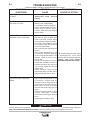
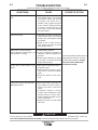
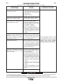
Troubleshooting Guide.............................................................................E-2 thru E-6
________________________________________________________________________
917B1=C1>49=5>C9?>%B9>D (53D9?>
000000000000000000000000000000000000000000000000000000000000000000000000
%1BDC!9CD%
000000000000000000000000000000000000000000000000000000000000000000000000

'#'P
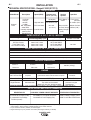
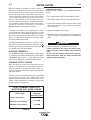
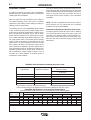
1. Output rating in watts is equivalent to volt-amperes at unity power factor. Output voltage is within ± 10% at all loads up to
rated capacity. When welding, available auxiliary power will be reduced.
* Top of enclosure add 6in. (152mm) for exhaust pipe.
** Engine warranty may vary outside of the USA. (See Engine warranty for details)
#()!!)$#
)#!(%)$#('1>75BP
"1;5"?45< 5C3B9@D9?> (@554'%" 9C@<135=5>D (D1BD9>7 1@139D95C
3E9>3E3= (ICD5=
3 cylinder 43.88(789)
12VDC Battery &
Fuel: 12 gal.
4 stroke starter (45 Liters)
18.8 HP High Idle 3650
Bore x Stroke inch (mm)
Oil: 3.4Qts. (3.2L)
Kubota** (14 KW)
D722 Net intermittent Full Load 3500
2.64 x 2.68
(Group 58; 550 Radiator Coolant:
3600 RPM (67 x 68 mm) cold crank amps) 3.85Qts. (3.6L)
naturally aspirated Low Idle 2450 Battery Charger
water cooled (3.6L)
Diesel Engine
#%*)(!##
')$*)%*)NN,!'
) ,) %) ,)
30.00* in. 21.50 in 52.25 in.
762.0 mm 546.0 mm 1327.0 mm
!*')$#"(($#( *!(.()" $+'#$'
Full Pressure Certified to EPA Tier 4
Mechanical Fuel Pump, Auto air bleed
Mechanical
with Full Flow Filter
Compliant
system Electric shutoff solenoid Indirect fuel injector
Governor
'!#' ##!' "*!' ##%'$))$#
Low noise Muffler: Shutdown on low oil
Single Element Automatic Idler Top outlet can be rotated. pressure & engine
Made from long life, aluminized steel. temperature
##,''#). 2 year complete (parts and labor) 3rd. year major components (parts and labor)
,5<49>7%B?35CC
DC Constant Current
DC Pipe Current
Touch-Start™TIG
DC Constant Voltage
$ED@ED'1>75
20 TO 305 AMPS
40 TO 300 AMPS
20 TO 250 AMPS
14 TO 29 VOLTS
Max. Weld OCV
@Rated Load RPM
60 Volts
,5<49>7$ED@ED
EBB5>D+?<D175EDII3<5
305A / 29V / 100%
300A / 29V / 100%
250A / 30V / 100%
300A / 29V / 100%
EH9<91BI%?G5B
10,000 Watts Peak, / 9,500 Watts Continuous, 60 Hz 120/240 Volts
(?E>4!5F5<C
Sound Power: 104.2 dB Lwa, Sound Level: 80.6 dBA @ 23 ft ( 7m )
%.(!"#($#(
##
'%)!(*-!'.%$,''*)' '$)''*)' '(
(2) 120VAC GFCI Duplex (5-20R) Two 20AMP for Two Duplex Receptacle 15AMP for Battery Charging Circuit
(1) 120/240VAC Dual Voltage One 50AMP for Dual Voltage(2-pole) 15AMP for 42V Wire Feeder Power
Full KVA (14-50R)
'%)!(#'*)' '(
')$*)%*)NN
.
#')$'
698 lbs. (317kg.)

!)#
The RANGER® 305D weighs approximately
775lbs.(352kg.) with a full tank of fuel (698 lbs. less
fuel). A lift bail is mounted to the machine and should
always be used when lifting the machine.
!))*$%')$#
At higher altitudes, output derating may be necessary. For max-
imum rating, derate the machine 2.5% to 3.5% for every 1000 ft.
(305m). Due to new EPA and other local emissions regulations,
modifications to the engine for high altitude are restricted within
the United States and some other European Countries. Use
above 6000 ft.(1828 m) may be limited due to poor engine per-
formance or excessive exhaust smoke. An authorized Kubota
engine field service shop should be contacted to determine if
any adjustments can be made for operation in higher elevations
locally.
)"%')*'$%')$#
At temperatures above 104°F(40°C), Welder output derating is
necessary. For maximum output ratings, derate the welder out-
put 2 volts for every 50°F(10°C) above 104°F(40°C).
?<4G51D85BCD1BD9>7
With a fully charged battery and the proper weight oil,
the engine should start satisfactorily even down to
about 5°F (-15°C). If the engine must be frequently
started at or below 23°F (-5°C), it may be desirable to
install cold-starting aides. The use of No. 1D diesel
fuel is recommended in place of No. 2D at tempera-
tures below 23°F (-5°C). Allow the engine to warm up
before applying a load or switching to high idle.
#?D5 Extreme cold weather starting may require
longer glow plug operation.
*>45B>?3?>49D9?>CC8?E<45D85B?B?D85BCD1BD9>7
6<E94C25EC54G9D8D89C5>79>5
--------------------------------------------------------------------------------
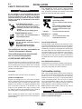
,'##
#()!!)$#
'#'P
().%'*)$#(
$><IAE1<96954@5BC?>>5<C8?E<49>CD1<<
EC5?BC5BF935D89C5AE9@=5>D
!$)$##+#)!)$#
The welder should be located to provide an unrestrict-
ed flow of clean, cool air to the cooling air inlets and to
avoid restricting the cooling air outlets. Also, locate the
welder so that the engine exhaust fumes are properly
vented to an outside area.
() #
RANGER® 305D machines cannot be stacked.
#!$$%')$#
Engines are designed to run in the level condition
which is where the optimum performance is achieved.
The maximum angle of continuous operation is 20
degrees in all directions, 35 degrees Intermittent (less
than 10 minutes continuous) in all directions. If the
engine is to be operated at an angle, provisions must
be made for checking and maintaining the oil level at
the normal (FULL) oil capacity in the crankcase.
When operating the welder at an angle, the effective
fuel capacity will be slightly less than the specified 12
gallons (45ltrs.).
? >?D 1DD5=@D D? EC5 D89C 5AE9@=5>D E>D9<I?E
81F5 D8?B?E78<I B514D855>79>5=1>E613DEB5BWC
=1>E1<CE@@<954 G9D8 I?EB G5<45B D9>3<E45C
9=@?BD1>D C165DI@B531ED9?>C 45D19<545>79>5
CD1BD9>7?@5B1D9>7 1>4=19>D5>1>35 9>CDBE3D9?>C
1>4@1BDC<9CDC
!)'($ 31>;9<<
O?>?DD?E385<53DB931<<I<9F5@1BDC?B
5<53DB?45G9D8C;9>?BG5D3<?D89>7
O>CE<1D5 I?EBC5<66B?=G?B; 1>4
7B?E>4
O<G1ICG51B4BI9>CE<1D9>77<?F5C
##V-*()V31>;9<<
O*C59>?@5> G5<<F5>D9<1D54 1B51C?B
F5>D5H81ECD?EDC945
"$+#%')(V31>9>:EB5
O?>?D ?@5B1D5 G9D8 4??BC ?@5> ?B
7E1B4C?66
O(D?@5>79>5256?B5C5BF939>7
O 55@1G1I6B?==?F9>7@1BDC
(55 1449D9?>1< G1B>9>79>6?B=1D9?> 1D
6B?>D?6D89C?@5B1D?BWC=1>E1<
,'##
O!96D?><IG9D85AE9@=5>D?6145
AE1D5<96D9>731@139DI
O5CEB5=1389>59CCD12<5G85><96D
9>7
O?>?D<96DD89C=1389>5EC9>7<96D
219<969D9C5AE9@@54G9D81851FI
1335CC?BICE381CDB19<5B?B71C
3I<9>45B
!!# O?>?D<96D=1389>596<96D219<9C
&*%"#)31>41=1754
31EC59>:EBIO?>?D?@5B1D5=1389>5G89<5
CEC@5>4546B?=<96D219<
--------------------------------------------------------------------------------
,'##

%'$%')$###('+
READ the engine operating and maintenance instruc-
tions supplied with this machine.
O(D?@5>79>51>41<<?GD?3??<256?B56E5<9>7
O?>?DC=?;5G85>6E5<9>7
O9<<6E5<D1>;1D1=?45B1D5B1D51>44?>?D?F5B
69<<
O ,9@5E@C@9<<54 6E5<1>4 1<<?G6E=5C D? 3<51B
256?B5CD1BD9>75>79>5
O 55@C@1B;C1>46<1=51G1I6B?=D1>;
--------------------------------------------------------------------------------
$!
The RANGER® 305D is shipped with the engine
crankcase filled with high quality SAE 10W-30 Oil that
meets classification CG-4 or CH-4 for diesel engines.
Check the oil level before starting the engine. If it is
not up to the full mark on the dip stick, add oil as
required. Check the oil level every four hours of run-
ning time during the first 50 running hours. Refer to
the engine Operator’s Manual for specific oil recom-
mendations and break-in information. The oil change
interval is dependent on the quality of the oil and the
operating environment. Refer to the Engine Operator’s
Manual for more details on the proper service and
maintenance intervals.
*!
(!*!$#!.!?GCE<@8EB6E5<?BE<DB1<?G
CE<@8EB6E5<9>*(1>41>141
O9<< D856E5< D1>; G9D83<51> 6B5C86E5<)85
31@139DI?6D85D1>;9C71<C<DBC,85>
D856E5<71E75 B514C5=@DID85 D1>; 3?>D19>C
1@@B?H9=1D5<I71<C<DBC?6B5C5BF56E5<
#$)6E5<C8ED?66F1<F59C<?31D54?>D85@B5
69<D5BC549=5>D 69<D5B ,8938C8?E<4259>
D853<?C54@?C9D9?>G85>D85G5<45B9C>?D
B1>6?B5HD5>454@5B9?4C?6D9=5
--------------------------------------------------------------------------------
#()!!)$#
'#'P
)$,#
The recommended trailer for use with this equipment for road,
in-plant and yard towing by a vehicle(1) is Lincoln’s K957-1. If
the user adapts a non-Lincoln trailer, he must assume responsi-
bility that the method of attachment and usage does not result
in a safety hazard nor damage the welding equipment. Some of
the factors to be considered are as follows:
1. Design capacity of trailer vs. weight of Lincoln equipment and
likely additional attachments.
2. Proper support of, and attachment to, the base of the weld-
ing equipment so there will be no undue stress to the frame-
work.
3. Proper placement of the equipment on the trailer to insure
stability side to side and front to back when being moved
and when standing by itself while being operated or ser-
viced.
4. Typical conditions of use, i.e., travel speed; roughness of sur-
face on which the trailer will be operated; environmental con-
ditions; like maintenance.
5. Conformance with federal, state and local laws.
Consult applicable federal, state and local laws regarding specific
requirements for use on public highways.
,'##
,'##
,'##
+!"$*#)#
=@B?@5B<I=?E>D54 3?>35>DB1D54 <?14C =1I
31EC5E>CD12<5F5893<581>4<9>71>4D9B5C?B?D85B
3?=@?>5>DCD?619<
O$><I DB1>C@?BD D89CAE9@=5>D?> C5BF93512<5
F5893<5CG89381B5B1D541>445C97>546?BCE38
<?14C
O9CDB92ED521<1>351>4C53EB5<?14CC?F5893<5
9CCD12<5E>45B3?>49D9?>C?6EC5
O?>?D5H3554=1H9=E=B1D54<?14C6?B3?=@?
>5>DCCE381CCEC@5>C9?>1H<5C1>4D9B5C
O"?E>D5AE9@=5>D21C5D?=5D1<254?B6B1=5?6
F5893<5
O?<<?GF5893<5=1>E613DEB5BWC9>CDBE3D9?>C
--------------------------------------------------------------------------------
,'##

#()!!)$#
'#'P
'"$)$#)'$!
The RANGER® 305D is equipped with a 6-pin and a
14-pin connector. The 6-pin connector is for connect-
ing the K857 or K857-1 Remote Control or for TIG
welding, the K870 foot Amptrol or the K936-3 hand
Amptrol. When in the CC-STICK, DOWNHILL PIPE,
or CV-WIRE modes and when a remote control is
connected to the 6-pin Connector, the auto-sensing
circuit automatically switches the OUTPUT control
from control at the welder to remote control.
When in TOUCH START TIG mode and when a
Amptrol is connected to the 6-Pin Connector, the
OUTPUT dial is used to set the maximum current
range of the CURRENT CONTROL of the Amptrol.
The 14-pin connector is used to directly connect a
wire feeder control cable. In the CV-WIRE mode,
when the control cable is connected to the 14-pin con-
nector, the auto-sensing circuit automatically makes
the Output Control inactive and the wire feeder volt-
age control active
#$),85>1G9B565545BG9D812E9<D9>G5<49>7
F?<D1753?>DB?<9C3?>>53D54D?D85@9>3?>>53
D?B4?>?D3?>>53D1>ID89>7D?D85@9>3?>>53
D?B
--------------------------------------------------------------------------------
!)'!$##)$#(
"#'$*##
Because this portable engine driven welder creates its
own power, it is not necessary to connect its frame to
an earth ground, unless the machine is connected to
premises wiring (home, shop, etc.)
To prevent dangerous electric shock, other equipment
to which this engine driven welder supplies power
must:
O57B?E>454D?D856B1=5?6D85G5<45BEC9>71
7B?E>454DI@5@<E7
O54?E2<59>CE<1D54
O?>?D7B?E>4D85=1389>5D?1@9@5D81D31BB95C
5H@<?C9F5?B3?=2ECD92<5=1D5B91<
--------------------------------------------------------------------------------
,'##
##$$!#(.()"
9BD?3??<D855>79>59C4B1G>9>D85 21C5C945C
1>4 5H81ECD D8B?E78B1491D?B 31C5213; D 9C
9=@?BD1>D D81D D859>D1;51>45H81ECD 19B9C >?D
B5CDB93D54<<?G 1 =9>9=E=3<51B1>35?6 655D
=6B?=D8531C5213;1>49>==6B?=
59D85BC945?6D8521C5D?1F5BD931<CEB6135.
--------------------------------------------------------------------------------
))'.$##)$#
*C531ED9?>1CD855<53DB?<ID59C1CDB?>71394D81D
31>2EB>C;9>1>441=1755I5C
--------------------------------------------------------------------------------
The RANGER® 305D is shipped with the negative
battery cable disconnected. Make certain that the
RUN-STOP switch is in the STOP position. Remove
the two screws from the rear battery tray using a
screwdriver or a 3/8" socket. Attach the negative bat-
tery cable to the negative battery terminal and tighten
using a 1/2" socket or wrench.
#$): This machine is furnished with a wet charged
battery; if unused for several months, the battery may
require a booster charge. Be careful to charge the bat-
tery with the correct polarity.
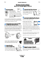
"*!'$*)!)%%
Using the clamp provided secure the outlet pipe to the
outlet tube with the pipe positioned such that it will
direct the exhaust in the desired direction. Tighten
using a 9/16" socket or wrench.
(%' ''()'
Some federal, state or local laws may require that
gasoline or diesel engines be equipped with exhaust
spark arresters when they are operated in certain
locations where unarrested sparks may present a fire
hazard. The standard muffler included with this welder
does not qualify as a spark arrester. When required by
local regulations, a suitable spark arrester, such as
the K1898-1 must be installed and properly main-
tained.
>9>3?BB53DC@1B;1BB5CD?B=1I<514D?41=175D?
D855>79>5?B14F5BC5<I16653D@5B6?B=1>35
--------------------------------------------------------------------------------
*)$#
,'##
,'##
,'##

!#()!!)$#
Install the welding cables to your RANGER® 305D as
follows.
1. The engine must be OFF to install welding cables.
2. Remove the flanged nuts from the output terminals
.
3. Connect the electrode holder and work cables to the
weld output terminals. The terminals are identified
on the case front.
4. Tighten the flanged nuts securely.
5. Be certain that the metal piece you are welding (the
“work”) is properly connected to the work clamp and
cable.
6. Check and tighten the connections periodically.
O!??C53?>>53D9?>C G9<< 31EC5 D85 ?ED@ED D5B=9
>1<C D??F5B851D)85D5B=9>1<C =1I5F5>DE1<<I
=5<D
O?>?D3B?CCD85G5<49>7312<5C1DD85?ED@EDD5B
=9>1< 3?>>53D9?> 55@D85 312<5C 9C?<1D54 1>4
C5@1B1D56B?=?>51>?D85B
--------------------------------------------------------------------------------
*)$#
#()!!)$#
'#'P
When this welder is mounted on a truck or trailer, its
frame must be electrically bonded to the metal frame
of the vehicle. Use a #8 or larger copper wire connect-
ed between the machine grounding stud and the
frame of the vehicle. When this engine driven welder
is connected to premises wiring such as that in a
home or shop, its frame must be connected to the sys-
tem earth ground. See further connection instructions
in the section entitled "Standby Power Connections"
as well as the article on grounding in the latest
National Electrical Code and the local code.
In general, if the machine is to be grounded, it should
be connected with a #8 or larger copper wire to a solid
earth ground such as a metal water pipe going into the
ground for at least ten feet and having no insulated
joints, or to the metal framework of a building which
has been effectively grounded.
The National Electrical Code lists a number of alter-
nate means of grounding electrical equipment. A
machine grounding stud marked with the symbol
is provided on the front of the welder.
,!#)'"#!(
The RANGER® 305D is equipped with a toggle switch
for selecting "hot" welding terminal when in the "WELD
TERMINALS ON" position or "cold" welding terminal
when in the "REMOTELY CONTROLLED" position.
,!#$*)%*)!(
With the engine off connect the electrode and work
cables to the output studs. The welding process dic-
tates the polarity of the electrode cable. These con-
nections should be checked periodically and tightened
with a 3/4" wrench.
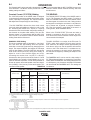
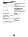
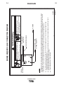
Table A.1 lists recommended cable sizes and lengths
for rated current and duty cycle. Length refers to the
distance from the welder to the work and back to the
welder. Cable diameters are increased for long cable
lengths to reduce voltage drops.
)!
)$)!$"#!#)$
!)'$#,$' !(
12<5!5>7D8
D=5D5BC
D=5D5BC
D=5D5BC
12<5(9J56?B
=@C
EDII3<5
,
,
,

#()!!)$#
'#'
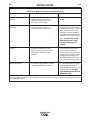
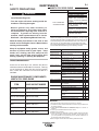
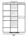
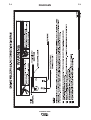
TABLE lll
ELECTRICAL DEVICE USE WITH THE RANGER® 305D
)I@5 ?==?><53DB931<5F935C %?CC92<5?>35B>C
Resistive Heaters, toasters, incandescent NONE
light bulbs, electric range, hot
pan, skillet, coffee maker.
Capacitive TV sets, radios, microwaves, Voltage spikes or high voltage
appliances with electrical control. regulation can cause the capaci-
tative elements to fail. Surge
protection, transient protection,
and additional loading is recom-
mended for 100% fail-safe oper-
ation. DO NOT RUN THESE
DEVICES WITHOUT ADDI-
TIONAL RESISTIVE TYPE
LOADS.
Inductive Single-phase induction motors, These devices require large
drills, well pumps, grinders, small current inrush for starting.
refrigerators, weed and hedge Some synchronous motors may
trimmers be frequency sensitive to attain
maximum output torque, but
they SHOULD BE SAFE from
any frequency induced failures.
Capacitive/Inductive Computers, high resolution TV sets, An inductive type line condition-
complicated electrical equipment. er along with transient and
surge protection is required, and
liabilities still exist. DO NOT
USE THESE DEVICES WITH A
RANGER® 305D
The Lincoln Electric Company is not responsible for any damage to electrical components improperly connected
to the RANGER® 305D.

*-!'.%$,''%)!(
Start the engine and set the “IDLER” control switch to
the “High Idle” mode. Voltage is now correct at the
receptacles for auxiliary power. This must be done
before a tripped GFCI receptacle can be reset prop-
erly. See the MAINTENANCE section for detailed
information on testing and resetting the GFCI recep-
tacle.
The auxiliary power of the RANGER® 305D consists
of two 20 Amp-120 VAC (5-20R) duplex receptacles
with GFCI protection and one 50 Amp 120/240 VAC
(14-50R) receptacle. The 240 VAC receptacle can be
split for single phase 120 VAC operation.
The auxiliary power capacity is 10,000 watts Peak,
9,500 Watts Continuous of 60 Hz, single phase
power. The auxiliary power capacity rating in watts is
equivalent to volt-amperes at unity power factor. The
max permissible current of the 240 VAC output is 40
amps. The 240 VAC output can be split to provide
two separate 120 VAC outputs with a max permissi-
ble current of 40 Amps per output to two separate
120 VAC branch circuits (these circuits cannot be
paralleled). Output voltage is within ± 10% at all loads
up to rated capacity. All auxiliary power is protected
by circuit breakers.
The 120 V auxiliary power receptacles should only be
used with three wire grounded type plugs or
approved double insulated tools with two wire plugs.
The current rating of any plug used with the system
must be at least equal to the current capacity of the
associated receptacle.
#$) The 240 V receptacle has two 120 V circuits,
but are of opposite polarities and cannot be paral-
leled.
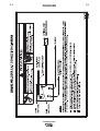
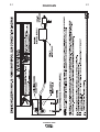
()#.%$,'$##)$#(
The RANGER® 305D is suitable for temporary,
standby or emergency power using the engine manu-
facturer’s recommended maintenance schedule.
The RANGER® 305D can be permanently installed
as a standby power unit for 240 VAC, 3 wire, single
phase, 40 amp service. Connections must be made
by a licensed electrician who can determine how the
120/240 VAC power can be adapted to the particular
installation and comply with all applicable electrical
codes.
#()!!)$#
'#'P
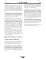
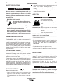
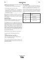
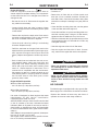
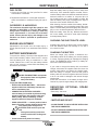
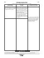
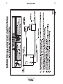
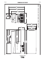
• Install the double-pole, double-throw switch
between the power company meter and the premis-
es disconnect. Switch rating must be the same or
greater than the customer’s premises disconnect
and service over current protection.
• Take necessary steps to assure load is limited to
the capacity of the RANGER® 305D by installing a
50 amp, 240 VAC double pole circuit breaker.
Maximum rated load for each leg of the 240 VAC
auxiliary is 40 amperes. Loading above the rated
output will reduce output voltage below the allow-
able - 10% of rated voltage which may damage
appliances or other motor-driven equipment and
may result in overheating of the RANGER® 305D
engine and/or alternator windings.
• Install a 50 amp, 120/240 VAC plug (NEMA Type
14-50) to the double-pole circuit breaker using No.
6, 4 conductor cable of the desired length. (The 50
amp, 120/240 VAC plug is available in the optional
K802R plug kit or as part number T12153-9.)
• Plug this cable into the 50 Amp, 120/240 Volt recep-
tacle on the RANGER® 305D case front.

#()!!)$#
'#'P
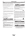
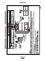
$##)$#$'#'P)$%'"((,'#
,'##
O$><I 1 <935>C54 35BD96954DB19>545<53DB9391> C8?E<49>CD1<< D85 =1389>5 D? 1 @B5=9C5C?BB5C945>D91<
5<53DB931<CICD5=535BD19>D81D
O)859>CD1<<1D9?>3?=@<95CG9D8D85#1D9?>1<<53DB931<?451>41<<?D85B1@@<9312<55<53DB931<3?45C
O )85@B5=9C5C 9C 9C?<1D541>4 >? 6554213;9>D? D85 ED9<9DI CICD5= 31>?33EB 5BD19>CD1D51>4<?31<
<1GCB5AE9B5D85@B5=9C5CD?259C?<1D54256?B5D85 75>5B1D?B 9C<9>;54 D?D85@B5=9C5C 853; I?EB
CD1D51>4<?31<B5AE9B5=5>DC
O 4?E2<5 @?<54?E2<5D8B?G DB1>C65B CG9D389> 3?>:E>3D9?> G9D8 D85@B?@5B<IB1D544?E2<5D8B?G
39B3E9D2B51;5B9C3?>>53D5425DG55>D8575>5B1D?B@?G5B1>4D85ED9<9DI=5D5B
2
40 Volt
60 Hz.
3
-Wire
Service
POWER
COMPANY
METER
2
40 VOLT
120 VOLT
120 VOLT
LOAD
N
N
EUTRAL
BUS
G
ROUND
PREMISES
D
ISCONNECT AND
SERVICE
O
VERCURRENT
PROTECTION
GND
N
NOTE: No. 6 COPPER CONDUCTOR CABLE SEE
NATIONAL ELECTRICAL CODE FOR ALTERNATE WIRE
SIZE RECOMMENDATIONS.
240 VOLT
GROUNDED CONDUCTOR
5
0AMP
240 VOLT
D
OUBLE
POLE
C
IRCUIT
BREAKER
DOUBLE POLE DOUBLE THROW
S
WITCH RATING TO BE THE SAME
A
S OR GREATER THAN PREMISES
SERVICE OVERCURRENT
PROTECTION.
5
0 AMP, 120/240
VOLT PLUG
NEMA TYPE 14-50
50 AMP, 120/240 VOLT
RECEPTACLE
2
40 Volt
60 Hz.
3
-Wire
Service
POWER
COMPANY
METER
2
40 VOLT
120 VOLT
120 VOLT
LOAD
N
N
EUTRAL
BUS
G
ROUND
PREMISES
D
ISCONNECT AND
SERVICE
O
VERCURRENT
PROTECTION
GND
N
NOTE: No. 6 COPPER CONDUCTOR CABLE SEE
NATIONAL ELECTRICAL CODE FOR ALTERNATE WIRE
SIZE RECOMMENDATIONS.
240 VOLT
GROUNDED CONDUCTOR
5
0AMP
240 VOLT
D
OUBLE
POLE
C
IRCUIT
BREAKER
DOUBLE POLE DOUBLE THROW
S
WITCH RATING TO BE THE SAME
A
S OR GREATER THAN PREMISES
SERVICE OVERCURRENT
PROTECTION.
5
0 AMP, 120/240
VOLT PLUG
NEMA TYPE 14-50
50 AMP, 120/240 VOLT
RECEPTACLE

#()!!)$#
'#'P
$##)$# $ !#$!#!)'
,''(
?>>53D9?>?6!#?B!#D?D85'#'P
O(8EDD85G5<45B?66
• Connect the LN-7 or LN-8 per instructions on the
appropriate connection diagram in Section F.
• Set the "WIRE FEEDER VOLTMETER" switch to
either "+" or "-" as required by the electrode being
used.
• Set the "MODE" switch to the "CV WIRE " position.
• Set the "ARC CONTROL" knob to "0" initially and
adjust to suit.
• Set the "WELD TERMINALS" switch to the
"REMOTELY CONTROLLED" position.
• Set the "IDLE" switch to the "HIGH" position.
?>>53D9?>?6!#D?D85'1>75BP
These connections instructions apply to both the LN-
15 Across The-Arc and Control Cable models. The
LN-15 has an internal contactor and the electrode is
not energized until the gun trigger is closed. When the
gun trigger is closed the wire will begin to feed and the
welding process is started.
O(8EDD85G5<45B?66
• For electrode Positive, connect the electrode cable
to the "+" terminal of the welder and work cable to
the "-" terminal of the welder. For electrode
Negative, connect the electrode cable "-" terminal of
the welder and work cable to the "+" terminal of the
welder.
O3B?CC)85B3"?45<
Attach the single lead from the front of the LN-15 to
work using the spring clip at the end of the lead. This
is a control lead to supply current to the wire feeder
motor; it does not carry welding current.
Set the "WELD TERMINALS" switch to "WELD TER-
MINALS ON"
O?>DB?<12<5"?45<
Connect Control Cable between Engine Welder and
Feeder.
Set the "WELD TERMINALS" switch to "REMOTELY
CONTROLLED".
• Set the MODE switch to the "CV-WIRE " position.
• Set the "WIRE FEEDER VOLTMETER" switch to
either "+" or "-" as required by the electrode polarity
being used.
• Set the "ARC CONTROL" knob to "0" initially and
adjust to suit.
• Set the "IDLE" switch to the "AUTO" position

#()!!)$#
'#'P
?>>53D9?> ?6!#(@??< E> 1>4
?2B1=1D93D?'#'P
O(8EDD85G5<45B?66
• Connect per instructions on the appropriate connec-
tion diagram in Section F.
?>>53D9?> ?6 %'# -!(%$$!*# D? D85
'1>75BP
Connection of the Prince XL Spool Gun requires the
use of the K1849-1 Adapter Module.
O(8EDD85,5<45B?66
• For electrode Positive, connect the electrode cable
to the "+" terminal of the welder and work cable to
the "-" terminal of the welder. For electrode
Negative, connect the electrode cable "-" terminal of
the welder and work cable to the "+" terminal of the
welder.
• Connect the Control Cable of the Spool Gun to the
Adapter Module and connect the Control Cable of
the Adapter Module to the Welder.
• Connect the Gas Hose.
• Set the MODE switch to the "CV-WIRE " position.
• Set the "WELD TERMINALS" switch to "WELD
TERMINALS ON".
• Set the "ARC CONTROL" knob to "0" initially and
adjust to suit.
• Set the “IDLE” switch to the “HIGH” position.
?>>53D9?>?6D85!#D?D85'#'P
(8ED?66G5<45B256?B5=1;9>71>I5<53DB931<3?>
>53D9?>C
--------------------------------------------------------------------------------
The LN-25 with or without an internal contactor may
be used with the RANGER® 305D. See the appropri-
ate connection diagram in Section F.
(8EDD85G5<45B?66
2. For electrode Positive, connect the electrode
cable from the LN-25 to the "+" terminal of the
welder and work cable to the "-" terminal of the
welder. For electrode Negative, connect the elec-
trode cable from the LN-25 to the "-" terminal of
the welder and work cable to the "+" terminal of
the welder.
3. Attach the single lead from the front of the LN-25
to work using the spring clip at the end of the lead.
This is a control lead to supply current to the wire
feeder motor; it does not carry welding current.
4. Set the MODE switch to the "CV-WIRE " position.
5. Set the "WELD TERMINALS" switch to "WELD
TERMINALS ON"
6. Set the "ARC CONTROL" knob to "0" initially and
adjust to suit.
7. Set the "IDLE" switch to the "AUTO" position.
When not welding, the RANGER® 305D engine
will be at the low idle speed. If you are using an
LN-25 with an internal contactor, the electrode is
not energized until the gun trigger is closed.
8. When the gun trigger is closed, the current sens-
ing circuit will cause the RANGER® 305D engine
to go to the high idle speed, the wire will begin to
feed and the welding process started. When weld-
ing is stopped, the engine will revert to low idle
speed after approximately 12 seconds unless
welding is resumed.
6I?E1B5EC9>71>!#G9D8?ED1>9>D5B>1<3?>
D13D?B D85 5<53DB?45 G9<<25 5>5B79J54 G85>D85
'1>75BP9CCD1BD54
--------------------------------------------------------------------------------
,'##
*)$#

$%')$#
'#'P
().%'*)$#(
? >?D1DD5=@D D? EC5 D89C5AE9@=5>DE>D9<I?E
81F5 D8?B?E78<IB514D85 5>79>5=1>E613DEB5BWC
=1>E1< CE@@<954G9D8 I?EB G5<45B D9>3<E45C
9=@?BD1>D C165DI @B531ED9?>C 45D19<54 5>79>5
CD1BD9>7 ?@5B1D9>7 1>4 =19>D5>1>35 9>CDBE3D9?>C
1>4@1BDC<9CDC
!)'($ 31>;9<<
O?>?DD?E385<53DB931<<I<9F5@1BDC?B
5<53DB?45G9D8C;9>?BG5D3<?D89>7
O>CE<1D5 I?EBC5<66B?= G?B; 1>4
7B?E>4
O<G1ICG51B4BI9>CE<1D9>77<?F5C
O<G1IC?@5B1D5D85G5<45BG9D8D8589>7544??B
3<?C541>4D85C945@1>5<C9>@<135
O'51431B56E<<ID85(165DI %B531ED9?>C@175
256?B5 ?@5B1D9>7D89C =1389>5 <G1IC6?<<?G
D85C51>41>I ?D85BC165DI@B?354EB5C 9>3<E454
9> D89C =1>E1< 1>4 9> D85 >79>5 >CDBE3D9?>
"1>E1<
#'!('%)$#
The RANGER® 305D is a diesel engine powered DC
multi-process welding power source and 120 / 240
volt AC power generator. The engine drives a genera-
tor that supplies three phase power for the DC weld-
ing circuit and single phase power for the AC auxiliary
outlets. The DC welding control system uses state of
the art Chopper Technology (CT tm) for superior weld-
ing performance.
$'*-!'.%$,'
Start the engine and set the IDLER control switch to
the desired operating mode. Full power is available
regardless of the welding control settings providing no
welding current is being drawn.
The auxiliary power of the RANGER® 305D consists
of two 20 Amp-120 VAC (5-20R) duplex receptacles
with GFCI protection and one 50 Amp 120/240 VAC
(14-50R) receptacle. The 240 VAC receptacle can be
split for single phase 120 VAC operation. Also refer to
the AUXILIARY POWER OPERATION section later in
this chapter.
##$%')$#
Before Starting the Engine:
• Be sure the machine is on a level surface.
• Open top & side engine doors and remove the
engine oil dipstick and wipe it with a clean cloth.
Reinsert the dipstick and check the level on the dip-
stick.
• Add oil (if necessary) to bring the level up to the full
mark. Do not overfill. Close engine door.
• Check radiator for proper coolant level. (Fill if nec-
essary).
• See Engine Owner’s Manual for specific oil and
coolant recommendations.
*!
• Stop engine while fueling.
• Do not smoke when fueling.
• Keep sparks and flame away from
tank.
• Do not leave unattended while fuel-
ing.
• Wipe up spilled fuel and allow
fumes to clear before starting
engine.
• Do not overfill tank, fuel expan-
sion may cause overflow.
(!*!$#!.!?GCE<@8EB6E5<?BE<DB1<?G
CE<@8EB6E5<9>*(1>41>141
--------------------------------------------------------------------------------
• Remove the fuel tank cap.
• Fill the tank approximately 4 inches (100mm) from
the top of the filler neck to allow for fuel expansion .
DO NOT FILL THE TANK TO THE POINT OF
OVERFLOW.
• Replace the fuel cap and tighten securely.
• See Engine Owner’s Manual for specific fuel recom-
mendations.
' #%'$
Any engine will use a small amount of oil during its
“break-in” period. For the diesel engine on the
RANGER® 305D, break-in is about 50 running hours.
Check the oil every four hours during break-in.
Change the oil after the first 50 hours of
operation,every 100 hours thereafter. Change the oil
filter at the second oil change.
EB9>7 2B51;9>CE2:53D D85 '#'P D?
=?45B1D5<?14CF?94<?>7@5B9?4C BE>>9>7 1D
94<556?B5CD?@@9>7D855>79>5B5=?F51<<<?14C
1>41<<?GD855>79>5D?3??<C5F5B1<=9>ED5C
--------------------------------------------------------------------------------
,'##
,'##
*)$#
(!*!
31>31EC569B5

$%')$#
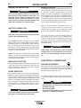
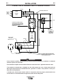
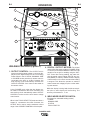
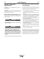
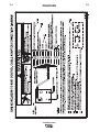
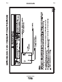
,!#$#)'$!( 97EB5
$*)%*)$#)'$!
The OUTPUT dial is
used to preset the output voltage or current as dis-
played on the digital meters for the four welding
modes. When in the CC-STICK, DOWNHILL PIPE
or CV-WIRE modes and when a remote control is
connected to the 6-Pin or 14-Pin Connector, the
auto-sensing circuit automatically switches the
OUTPUT CONTROL from control at the welder to
the remote control.
In the CV-WIRE mode, when the wire feeder con-
trol cable is connected to the 14-Pin Connector, the
auto-sensing circuit automatically makes OUTPUT
CONTROL inactive and the wire feeder voltage
control active.
When in the TOUCH START TIG mode and when a
Amptrol is connected to the 6-Pin Connector, the
OUTPUT dial is used to set the maximum current
range of the CURRENT CONTROL of the Amptrol.
)! $*)%*) ")'(The digital
meters allow the output voltage (CV-WIRE mode)
or current (CC-STICK,DOWN HILL PIPE and TIG
modes) to be set prior to welding using the OUT-
PUT control dial. During welding, the meter dis-
play the actual output voltage (VOLTS) and cur-
rent (AMPS). A memory feature holds the display
of both meters on for seven seconds after welding
is stopped. This allows the operator to read the
actual current and voltage just prior to when weld-
ing was ceased.
While the display is being held the left-most deci-
mal point in each display will be flashing. The
accuracy of the meters is +/- 3%.
,!"$(!)$'(,)
(Provides four selectable welding modes)
CV-WIRE
DOWNHILL PIPE
CC-STICK
TOUCH START TIG
'#'P
1
10
7
4
9
5
8
11
12
13
6
15
14
17
16
2
3
*'

$%')$#
'$#)'$!The ARC CONTROL dial is active in
the CV-WIRE, CC-STICK and DOWNHILL PIPE modes,
and has different functions in these modes. This control is
not active in the TIG mode.
() =?45 In this mode, the ARC CONTROL dial
sets the short circuit current (arc-force) during stick welding
to adjust for a soft or crisp arc. Increasing the dial from –10
(soft) to +10 (crisp) increases the short circuit current and
prevents sticking of the electrode to the plate while welding.
This can also increase spatter. It is recommended that the
ARC CONTROL be set to the minimum number without
electrode sticking. Start with a setting at 0.
$,#!!%%=?45 In this mode, the ARC CONTROL
dial sets the short circuit current (arc-force) during stick
welding to adjust for a soft or a more forceful digging arc
(crisp). Increasing the number from –10 (soft) to +10 (crisp)
increases the short circuit current which results in a more
forceful digging arc. Typically a forceful digging arc is pre-
ferred for root and hot passes. A softer arc is preferred for fill
and cap passes where weld puddle control and deposition
("stacking" of iron) are key to fast travel speeds. It is recom-
mended that the ARC CONTROL be set initially at 0.
+,'=?45 In this mode, turning the ARC CONTROL
clock wise from –10 (soft) to +10 (crisp) changes the arc
from soft and washed-in to crisp and narrow. It acts as an
inductance/pinch control. The proper setting depends on the
procedure and operator preference. Start with a setting of 0.
,! $*)%*) )'"#!(,) !#
#*) Provides a connection point for the electrode and
work cables.
'$*#()* Provides a connection point for
connecting the machine case to earth ground.
%#$##)$' For attaching wire feeder con-
trol cables to the RANGER® 305D. Includes contactor clo-
sure circuit, auto-sensing remote control circuit, and 120V
and 42V power. The remote control circuit operates the
same as the 6 Pin Amphenol.
%#$##)$' For attaching optional remote
control equipment. Includes auto-sensing remote control
circuit.
,!)'"#!($#)'$!(,) In the
WELD TERMINALS ON position, the output is electrically
hot all the time. In the REMOTELY CONTROLLED posi-
tion, the output is controlled by a wire feeder or amptrol
device, and is electrically off until a remote switch is
depressed.
,''+$!)")'(,)
Matches the polarity of the wire feeder voltmeter to
the polarity of the electrode.
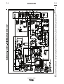
##$#)'$!(97EB5
'*#()$%(,)
- RUN position energizes
the engine prior to starting. STOP position stops the
engine. The oil pressure interlock switch prevents
battery drain if the switch is left in the RUN position
and the engine is not operating.
!$,%!*%*(*))$# -
• When pushed activates the glow plugs. Glow plug
should not be activated for more than 20 seconds
continuously.
()')%*(*))$# -
Energizes the starter motor to crank the
engine.
!'(,)- Has two positions as follows:
1) In the HIGH position, the engine runs at the high
idle speed controlled by the engine governor.
2) In the AUTO position, the idler operates as follows:
• When switched from HIGH to AUTO or after starting
the engine, the engine will operate at full speed for
approximately 12 seconds and then go to low idle
speed.
• When the electrode touches the work or power is
drawn for lights or tools (approximately 100 Watts
minimum), the engine accelerates and operates at
full speed.
• When welding ceases or the AC power load is
turned off, a fixed time delay of approximately 12
seconds starts. If the welding or AC power load is
not restarted before the end of the time delay, the
idler reduces the engine speed to low idle speed.
• The engine will automatically return to high idle
speed when there is welding load or AC power load
reapplied.
'#'P
Page is loading ...
Page is loading ...
Page is loading ...
Page is loading ...
Page is loading ...
Page is loading ...
Page is loading ...
Page is loading ...
Page is loading ...
Page is loading ...
Page is loading ...
Page is loading ...
Page is loading ...
Page is loading ...
Page is loading ...
Page is loading ...
Page is loading ...
Page is loading ...
Page is loading ...
Page is loading ...
Page is loading ...
Page is loading ...
Page is loading ...
Page is loading ...
Page is loading ...
Page is loading ...
Page is loading ...
Page is loading ...
Page is loading ...
Page is loading ...
Page is loading ...
Page is loading ...
Page is loading ...
-
 1
1
-
 2
2
-
 3
3
-
 4
4
-
 5
5
-
 6
6
-
 7
7
-
 8
8
-
 9
9
-
 10
10
-
 11
11
-
 12
12
-
 13
13
-
 14
14
-
 15
15
-
 16
16
-
 17
17
-
 18
18
-
 19
19
-
 20
20
-
 21
21
-
 22
22
-
 23
23
-
 24
24
-
 25
25
-
 26
26
-
 27
27
-
 28
28
-
 29
29
-
 30
30
-
 31
31
-
 32
32
-
 33
33
-
 34
34
-
 35
35
-
 36
36
-
 37
37
-
 38
38
-
 39
39
-
 40
40
-
 41
41
-
 42
42
-
 43
43
-
 44
44
-
 45
45
-
 46
46
-
 47
47
-
 48
48
-
 49
49
-
 50
50
-
 51
51
-
 52
52
-
 53
53
-
 54
54


Lincoln Electric 305D User manual
- Category
- Welding System
- Type
- User manual
Ask a question and I''ll find the answer in the document
Finding information in a document is now easier with AI
Related papers
-
Lincoln Electric IM929 User manual
-
-
Lincoln Electric Ranger 305D Operating instructions
-
-
-
-
-
Other documents
-
Lincoln IM985 User manual
-
Century K2964-1 AC-120 Stick Welder User manual
-
-
Audi Home EV Charger User guide
-
MQ Multiquip DlW330X2 Operating instructions
-
 MQ Multiquip DLW400ESA4 Operating instructions
-
-
-
 Active Thermal Management 00-301-03 Datasheet
-
Anova GCS5800E Owner's manual

