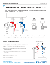
5. Connect water line and pressure relief drain line
a. Attach the HOT water supply line to the ¾" threaded con-
nection on the HOT WATER VALVE
using thread sealant on the threads
of the water fitting, sweat copper
pipe on TWH-FS models.
b. Attach the COLD water supply line
to the ¾" threaded connection on
the COLD WATER VALVE using
thread sealant on the threads of the
water fitting, sweat copper pipe on
TWH-FS models.
c. Attach the drain line to the pressure
relief valve and run to a safe place
of disposal.
WARNING
! To avoid water damage and/or scald-
ing due to valve operation, a discharge line must be
connected to valve outlet and run to a safe place of
disposal. The discharge line shall be installed to allow
complete drainage of both the valve and the discharge
line. No reducing coupling or other restriction shall be
installed in the discharge line. The discharge line must
pitch downward from the valve and terminate with a 6"
(152mm) air gap from an approved location or build-
ing drain. The discharge line must terminate through
plain (unthreaded) pipe. Discharge line material must
conform to local plumbing code or ASME requirements.
Excessive length - more than 30 feet (9.14m), use of
more than four elbows or bends in discharge piping, or
reduction of discharge line size will cause a restriction
and reduce the discharge capacity of the valve. No shut-
off valve shall be installed between the relief valve and
tank, or in the discharge line.
6. Start-up & Normal Operation
a. Before turning on the supply water to the heater, make sure
that the main valve handles on both the hot & cold valves
are closed (perpendicular to the main valve bodies). Also
ensure that the purge port valve caps are tightened down
and that the valves are in the closed position. NEVER RELY
ON THE PURGE CAP TO STOP THE WATER FLOW.
b. For water heater start-up, refer to the water heater owners’
manual.
c. During normal operation, the main water valves are open
when the main valve handle is parallel with the main valve
body and closed when the main valve handle is perpendicu-
lar to the main valve body.
d. For the purge port valves, the purge port valve is open when
the handle is parallel with the purge port valve body and closed
when the handle is perpendicular to the purge port valve.
7. Inspection and Maintenance
a. See tag attached to pressure relief valve for details.
WARNING
! Hot water may be present in the system,
use extreme caution when servicing tankless water
heater. Hot water can cause personal injury, death and/
or property damage.
8. Hot Valve Field Configuration
The LFTWHG2 hot valve assembly can
be field configured to better fit certain
installations.
The hot valve is factory configured to
position the main valve handle on the
left and the relief valve on the right with
the drain valve facing forward as shown
in Illustration 1. The valve can be field
configured to position the relief valve on
the left, the main valve handle on the
right with the drain port facing forward
as shown in Illustration 2.
Field configure the hot valve as fol-
lows;
1. With the valve in the closed position,
note the valve handle is facing in the
same direction as the drain port.
2. Remove the red handle retainer plug
by prying it out with a small screw-
driver, then remove the handle by
pulling straight off. With the handle removed, remove the
LEFT stop plate from the rotor stub.
3. Install the RIGHT stop plate on the keyed rotor stub (it can
only be installed in the correct position), then reinstall the
main valve handle facing the opposite direction away from
the drain port. Once the handle is snapped into place, re-
install the red handle retainer plug.
4. Remove the drain valve assembly and the secondary drain
port plug from the valve body.
5. Re-install the drain valve assembly in the opposite port so
it is facing the same direction as the closed valve handle.
Re-install the plug in the unused drain port.
Fig.5
Drain Line
Attach this end
to tankless
water heater
Hot Service Valve Purge Port Flow Data
Illustration 1 -
Factory Configuration
Illustration 2 -
Field Configured


