IS-LFTWHG2-FT/FS
Installation Instructions
Series LFTWHG2
Tankless Water Heater Valves with
VersaFit™ Technology
Sizes: 3⁄4" Service Valve Set
ATTENTION INSTALLER: After installation, please leave
this Instruction Sheet for occupant’s information.
IMPORTANT: Inquire with governing authorities for local
installation requirements.
Fig.4
STOP!
Before connecting any components, be sure to read all
of the tankless water heater manufacturer’s installation
instructions. Failure to follow instructions below can re-
sult in serious injury, death and/or property damage.
1. Identify all components and
orientations before beginning
installation
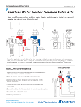
1. HOT WATER SERVICE VALVE (Fig.1)
Identified by the red handle insert.
2. COLD WATER SERVICE VALVE (Fig.2)
Identified by the blue handle insert.
3. PRESSURE RELIEF VALVE (Fig.3)
Identified by a silver test lever.
Note: ANSI Z21.22 and local codes
govern the installation of pressure
relief valves.
2. Before attaching any components
to the tankless water heater,
attach PRESSURE RELIEF VALVE
to HOT WATER ISOLATION
VALVE (Figure 4)
CAUTION
! Do not over tighten
relief valve. Do not tighten more
than one full turn past hand tight.
a. Apply thread sealant to the exposed
threads of the pressure relief valve.
b. Thread the pressure relief valve into
the 3⁄4" port on the side of the hot
water valve and hand tighten. Using
a wrench, tighten the pressure relief
valve until the discharge on the pres-
sure relief valve is positioned down-
ward on the isolation valve, as shown
in Figure 4.
Drain Line
Attach this end to
tankless water heater
Attach this end to
tankless water heater
3. Install COLD WATER SERVICE VALVE onto cold water
inlet of tankless water heater
a. Locate the cold water threaded inlet on the tankless water
heater and apply thread sealant to the threads.
b. Slightly loosen the union nut on the top of the cold water
valve so that the union tailpiece rotates freely.
c. Holding the cold water valve beneath the cold water inlet,
thread the union tailpiece onto the inlet and hand tighten.
Using a wrench, tighten the union tailpiece. Next, position
the cold water valve with the purge port pointing forward,
towards the front of the water heater, and hand tighten the
union nut.
d. Tighten the union nut with a wrench, making sure that the
valve does not rotate out of position.
4. Install HOT WATER SERVICE VALVE onto hot water
outlet of tankless water heater
WARNING
! There should not be a shutoff located
between the tankless water heater and pressure relief
valve. (See direction arrow in Fig. 5.)
a. Locate the hot water threaded outlet on the tankless water
heater and apply thread sealant to the threads.
b. Slightly loosen the union nut on the top of the hot water
valve so that the union tailpiece rotates freely.
c. Holding the hot water valve beneath the hot water outlet,
thread the union tailpiece onto the outlet and hand tighten.
Using a wrench, tighten the union tailpiece. Next, position
the hot valve with the purge port and pressure relief valve
pointing forward, towards the front of the water heater, and
hand tighten the union nut. Tighten the union nut with a
wrench, making sure that the valve does not rotate out of
position.
Fig.1
Fig.2
Fig.3
TWHG2
WARNING
!
Read this Manual BEFORE using this equipment.
Failure to read and follow all safety and use information
can result in death, serious personal injury, property
damage, or damage to the equipment.
Keep this Manual for future reference.
For valves with CPVC or PEX end connections do not exceed the
tubing manufacturers pressure and temperature ratings. Refer to the
tubing manufacturers product specifications for that information.
WARNING
!

5. Connect water line and pressure relief drain line
a. Attach the HOT water supply line to the ¾" threaded con-
nection on the HOT WATER VALVE
using thread sealant on the threads
of the water fitting, sweat copper
pipe on TWH-FS models.
b. Attach the COLD water supply line
to the ¾" threaded connection on
the COLD WATER VALVE using
thread sealant on the threads of the
water fitting, sweat copper pipe on
TWH-FS models.
c. Attach the drain line to the pressure
relief valve and run to a safe place
of disposal.
WARNING
! To avoid water damage and/or scald-
ing due to valve operation, a discharge line must be
connected to valve outlet and run to a safe place of
disposal. The discharge line shall be installed to allow
complete drainage of both the valve and the discharge
line. No reducing coupling or other restriction shall be
installed in the discharge line. The discharge line must
pitch downward from the valve and terminate with a 6"
(152mm) air gap from an approved location or build-
ing drain. The discharge line must terminate through
plain (unthreaded) pipe. Discharge line material must
conform to local plumbing code or ASME requirements.
Excessive length - more than 30 feet (9.14m), use of
more than four elbows or bends in discharge piping, or
reduction of discharge line size will cause a restriction
and reduce the discharge capacity of the valve. No shut-
off valve shall be installed between the relief valve and
tank, or in the discharge line.
6. Start-up & Normal Operation
a. Before turning on the supply water to the heater, make sure
that the main valve handles on both the hot & cold valves
are closed (perpendicular to the main valve bodies). Also
ensure that the purge port valve caps are tightened down
and that the valves are in the closed position. NEVER RELY
ON THE PURGE CAP TO STOP THE WATER FLOW.
b. For water heater start-up, refer to the water heater owners’
manual.
c. During normal operation, the main water valves are open
when the main valve handle is parallel with the main valve
body and closed when the main valve handle is perpendicu-
lar to the main valve body.
d. For the purge port valves, the purge port valve is open when
the handle is parallel with the purge port valve body and closed
when the handle is perpendicular to the purge port valve.
7. Inspection and Maintenance
a. See tag attached to pressure relief valve for details.
WARNING
! Hot water may be present in the system,
use extreme caution when servicing tankless water
heater. Hot water can cause personal injury, death and/
or property damage.
8. Hot Valve Field Configuration
The LFTWHG2 hot valve assembly can
be field configured to better fit certain
installations.
The hot valve is factory configured to
position the main valve handle on the
left and the relief valve on the right with
the drain valve facing forward as shown
in Illustration 1. The valve can be field
configured to position the relief valve on
the left, the main valve handle on the
right with the drain port facing forward
as shown in Illustration 2.
Field configure the hot valve as fol-
lows;
1. With the valve in the closed position,
note the valve handle is facing in the
same direction as the drain port.
2. Remove the red handle retainer plug
by prying it out with a small screw-
driver, then remove the handle by
pulling straight off. With the handle removed, remove the
LEFT stop plate from the rotor stub.
3. Install the RIGHT stop plate on the keyed rotor stub (it can
only be installed in the correct position), then reinstall the
main valve handle facing the opposite direction away from
the drain port. Once the handle is snapped into place, re-
install the red handle retainer plug.
4. Remove the drain valve assembly and the secondary drain
port plug from the valve body.
5. Re-install the drain valve assembly in the opposite port so
it is facing the same direction as the closed valve handle.
Re-install the plug in the unused drain port.
Fig.5
Drain Line
Attach this end
to tankless
water heater
Hot Service Valve Purge Port Flow Data
Illustration 1 -
Factory Configuration
Illustration 2 -
Field Configured

9. Modular Installations
When used in modular installations, the LFTWHG2 hot valve
assembly can be field configured to provide hydraulic isolation of
units that need service or repair while other units remain operat-
ing. To provide hydraulic isolation from a pressurized hot water
main, the pressure-activated seal must be rotated 180 degrees
from the bottom port to the upper port as follows;
1. With the valve in the closed position (handle facing forwards),
remove handle plug, handle and stop plate;
2. Place handle back on rotor hub and rotate 180 degrees so
handle is facing rearward;
3. Remove handle and re-install stop plate aligning the notch
(marked with a X) with the nub on the body;
4. Re-install handle (facing to the rear) and handle plug. The
valve will now provide hydraulic isolation from a pressurized
hot water main and be locked closed to prevent operation of
water heater.
5. To place heater back in commission, reverse the above pro-
cess.

Limited Warranty: Watts (the “Company”) warrants each product to be free from defects in material and workmanship under normal usage for a period of one year from the date of original shipment.
In the event of such defects within the warranty period, the Company will, at its option, replace or recondition the product without charge.
THE WARRANTY SET FORTH HEREIN IS GIVEN EXPRESSLY AND IS THE ONLY WARRANTY GIVEN BY THE COMPANY WITH RESPECT TO THE PRODUCT. THE COMPANY MAKES NO OTHER
WARRANTIES, EXPRESS OR IMPLIED. THE COMPANY HEREBY SPECIFICALLY DISCLAIMS ALL OTHER WARRANTIES, EXPRESS OR IMPLIED, INCLUDING BUT NOT LIMITED TO THE IMPLIED
WARRANTIES OF MERCHANTABILITY AND FITNESS FOR A PARTICULAR PURPOSE.
The remedy described in the first paragraph of this warranty shall constitute the sole and exclusive remedy for breach of warranty, and the Company shall not be responsible for any incidental, special
or consequential damages, including without limitation, lost profits or the cost of repairing or replacing other property which is damaged if this product does not work properly, other costs resulting
from labor charges, delays, vandalism, negligence, fouling caused by foreign material, damage from adverse water conditions, chemical, or any other circumstances over which the Company has no
control. This warranty shall be invalidated by any abuse, misuse, misapplication, improper installation or improper maintenance or alteration of the product.
Some States do not allow limitations on how long an implied warranty lasts, and some States do not allow the exclusion or limitation of incidental or consequential damages. Therefore the above
limitations may not apply to you. This Limited Warranty gives you specific legal rights, and you may have other rights that vary from State to State. You should consult applicable state laws to
determine your rights. SO FAR AS IS CONSISTENT WITH APPLICABLE STATE LAW, ANY IMPLIED WARRANTIES THAT MAY NOT BE DISCLAIMED, INCLUDING THE IMPLIED WARRANTIES OF
MERCHANTABILITY AND FITNESS FOR A PARTICULAR PURPOSE, ARE LIMITED IN DURATION TO ONE YEAR FROM THE DATE OF ORIGINAL SHIPMENT.
IS-LFTWHG2-FT-FS 2129 EDP# 1915465 © 2021 Watts
USA: T: (978) 689-6066 • F: (978) 975-8350 • Watts.com
Canada: T: (888) 208-8927 • F: (905) 332-7068 • Watts.ca
Latin America: T: (52) 55-4122-0138 • Watts.com
-
 1
1
-
 2
2
-
 3
3
-
 4
4
Ask a question and I''ll find the answer in the document
Finding information in a document is now easier with AI
Related papers
Other documents
-
Schlage ND Operating instructions
-
 Webstone, a brand of NIBCO 54443WPR Installation guide
-
 Webstone Company H-44444WPR3 Installation guide
-
 Webstone, a brand of NIBCO 54443WPRGST Installation guide
-
Rinnai RSC199iP User manual
-
Rinnai CU160EN User manual
-
State Water Heaters Package System User manual
-
Rinnai RU130iP User manual
-
 EasyFlex EFLF-ISV-HCTP Operating instructions
-
Rinnai REU-NP3237FF-US-N Installation guide


