
Mellanox Technologies
www.mellanox.com
Mellanox ConnectX®-5 and ConnectX®-5 Ex Ethernet
SFP28 and QSFP28 Ports Adapter Cards User Manual
P/N:
MCX512A-ACAT, MCX511F-ACAT, MCX512F-ACAT,MCX516A-BDAT, MCX515A-GCAT,
MCX516A-GCAT, MCX515A-CCAT, MCX516A-CCAT, MCX516A-CDAT
Rev 1.7

Doc #: MLNX-15-51360 2Mellanox Technologies
Mellanox Technologies
350 Oakmead Parkway Suite 100
Sunnyvale, CA 94085
U.S.A.
www.mellanox.com
Tel: (408) 970-3400
Fax: (408) 970-3403
© Copyright 2018. Mellanox Technologies Ltd. All Rights Reserved.
Mellanox®, Mellanox logo, Accelio®, BridgeX®, CloudX logo, CompustorX®, Connect-IB®, ConnectX®,
CoolBox®, CORE-Direct®, EZchip®, EZchip logo, EZappliance®, EZdesign®, EZdriver®, EZsystem®,
GPUDirect®, InfiniHost®, InfiniBridge®, InfiniScale®, LinkX®, Kotura®, Kotura logo, Mellanox CloudRack®,
Mellanox CloudXMellanox®, Mellanox Federal Systems®, Mellanox HostDirect®, Mellanox Multi-Host®, Mellanox
Open Ethernet®, Mellanox OpenCloud®, Mellanox OpenCloud Logo®, Mellanox PeerDirect®, Mellanox
ScalableHPC®, Mellanox StorageX®, Mellanox TuneX®, Mellanox Connect Accelerate Outperform logo, Mellanox
Virtual Modular Switch®, MetroDX®, MetroX®, MLNX-OS®, NP-1c®, NP-2®, NP-3®, NPS®, Open Ethernet logo,
PhyX®, PlatformX®, PSIPHY® , SiPhy®, StoreX®, SwitchX®, Tilera®, Tilera logo, TestX®, TuneX®, The
Generation of Open Ethernet logo, UFM®, Unbreakable Link®, Virtual Protocol Interconnect®, Voltaire® and
Voltaire logo are registered trademarks of Mellanox Technologies, Ltd.
All other trademarks are property of their respective owners.
For the most updated list of Mellanox trademarks, visit http://www.mellanox.com/page/trademarks
NOTE:
THIS HARDWARE , SOFTWARE OR TEST SUITE PRODUCT ( PRODUCT (S) ) AND ITS RELATED
DOCUMENTATION ARE PROVIDED BY MELLANOX TECHNOLOGIES AS-ISﺴ WITH ALL FAULTS OF ANY
KIND AND SOLELY FOR THE PURPOSE OF AIDING THE CUSTOMER IN TESTING APPLICATIONS THAT
USE THE PRODUCTS IN DESIGNATED SOLUTIONS . THE CUSTOMER 'S MANUFACTURING TEST
ENVIRONMENT HAS NOT MET THE STANDARDS SET BY MELLANOX TECHNOLOGIES TO FULLY
QUALIFY THE PRODUCT (S) AND/OR THE SYSTEM USING IT . THEREFORE , MELLANOX TECHNOLOGIES
CANNOT AND DOES NOT GUARANTEE OR WARRANT THAT THE PRODUCTS WILL OPERATE WITH THE
HIGHEST QUALITY . ANY EXPRESS OR IMPLIED WARRANTIES , INCLUDING, BUT NOT LIMITED TO , THE
IMPLIED WARRANTIES OF MERCHANTABILITY , FITNESS FOR A PARTICULAR PURPOSE AND
NONINFRINGEMENT ARE DISCLAIMED . IN NO EVENT SHALL MELLANOX BE LIABLE TO CUSTOMER OR
ANY THIRD PARTIES FOR ANY DIRECT , INDIRECT, SPECIAL , EXEMPLARY , OR CONSEQUENTIAL
DAMAGES OF ANY KIND (INCLUDING, BUT NOT LIMITED TO , PAYMENT FOR PROCUREMENT OF
SUBSTITUTE GOODS OR SERVICES ; LOSS OF USE , DATA , OR PROFITS ; OR BUSINESS INTERRUPTION )
HOWEVER CAUSED AND ON ANY THEORY OF LIABILITY , WHETHER IN CONTRACT , STRICT LIABILITY ,
OR TORT (INCLUDING NEGLIGENCE OR OTHERWISE ) ARISING IN ANY WAY FROM THE USE OF THE
PRODUCT (S) AND RELATED DOCUMENTATION EVEN IF ADVISED OF THE POSSIBILITY OF SUCH
DAMAGE .

Rev 1.7 3Mellanox Technologies
Table of Contents
Revision History . . . . . . . . . . . . . . . . . . . . . . . . . . . . . . . . . . . . . . . . . . . . . . . . . . 8
About This Manual . . . . . . . . . . . . . . . . . . . . . . . . . . . . . . . . . . . . . . . . . . . . . . . 9
Chapter 1 Introduction . . . . . . . . . . . . . . . . . . . . . . . . . . . . . . . . . . . . . . . . . . . 11
1.1 Product Overview . . . . . . . . . . . . . . . . . . . . . . . . . . . . . . . . . . . . . . . . . . . . . 12
1.2 Package Content. . . . . . . . . . . . . . . . . . . . . . . . . . . . . . . . . . . . . . . . . . . . . . 12
1.3 Features and Benefits. . . . . . . . . . . . . . . . . . . . . . . . . . . . . . . . . . . . . . . . . . 13
1.4 Operating Systems/Distributions . . . . . . . . . . . . . . . . . . . . . . . . . . . . . . . . 14
1.5 Connectivity . . . . . . . . . . . . . . . . . . . . . . . . . . . . . . . . . . . . . . . . . . . . . . . . . 14
Chapter 2 Interfaces . . . . . . . . . . . . . . . . . . . . . . . . . . . . . . . . . . . . . . . . . . . . . 15
2.1 Ethernet SFP28 and QSFP28 Interface . . . . . . . . . . . . . . . . . . . . . . . . . . . . 15
2.2 PCI Express Interface . . . . . . . . . . . . . . . . . . . . . . . . . . . . . . . . . . . . . . . . . . 15
2.3 LED Interface. . . . . . . . . . . . . . . . . . . . . . . . . . . . . . . . . . . . . . . . . . . . . . . . . 16
2.4 Heatsink Interface . . . . . . . . . . . . . . . . . . . . . . . . . . . . . . . . . . . . . . . . . . . . 16
2.5 SMBus Interface . . . . . . . . . . . . . . . . . . . . . . . . . . . . . . . . . . . . . . . . . . . . . . 16
2.6 Voltage Regulators . . . . . . . . . . . . . . . . . . . . . . . . . . . . . . . . . . . . . . . . . . . . 16
Chapter 3 Hardware Installation . . . . . . . . . . . . . . . . . . . . . . . . . . . . . . . . . . . 17
3.1 System Requirements . . . . . . . . . . . . . . . . . . . . . . . . . . . . . . . . . . . . . . . . . 18
3.1.1 Hardware Requirements . . . . . . . . . . . . . . . . . . . . . . . . . . . . . . . . . . . . . . . 18
3.1.2 Airflow Requirements. . . . . . . . . . . . . . . . . . . . . . . . . . . . . . . . . . . . . . . . . . 18
3.1.3 Software Requirements . . . . . . . . . . . . . . . . . . . . . . . . . . . . . . . . . . . . . . . . 19
3.1.3.1 Operating Systems/Distributions . . . . . . . . . . . . . . . . . . . . . . . . . . . . . . . . 19
3.1.3.2 Software Stacks . . . . . . . . . . . . . . . . . . . . . . . . . . . . . . . . . . . . . . . . . . . . . . 19
3.2 Safety Precautions . . . . . . . . . . . . . . . . . . . . . . . . . . . . . . . . . . . . . . . . . . . . 19
3.3 Pre-Installation Checklist . . . . . . . . . . . . . . . . . . . . . . . . . . . . . . . . . . . . . . . 19
3.4 Bracket Replacement Instructions . . . . . . . . . . . . . . . . . . . . . . . . . . . . . . . 20
3.4.1 Removing the Existing Bracket. . . . . . . . . . . . . . . . . . . . . . . . . . . . . . . . . . . 21
3.4.2 Installing the New Bracket . . . . . . . . . . . . . . . . . . . . . . . . . . . . . . . . . . . . . . 21
3.5 Installation Instructions . . . . . . . . . . . . . . . . . . . . . . . . . . . . . . . . . . . . . . . . 21
3.6 Cables and Modules . . . . . . . . . . . . . . . . . . . . . . . . . . . . . . . . . . . . . . . . . . . 23
3.6.1 Cable Installation. . . . . . . . . . . . . . . . . . . . . . . . . . . . . . . . . . . . . . . . . . . . . . 23
3.7 Adapter Card Uninstallation Instructions . . . . . . . . . . . . . . . . . . . . . . . . . . 24
3.7.1 Safety Precautions . . . . . . . . . . . . . . . . . . . . . . . . . . . . . . . . . . . . . . . . . . . . 24
3.7.2 Card Un-installation . . . . . . . . . . . . . . . . . . . . . . . . . . . . . . . . . . . . . . . . . . . 24
3.8 Identify the Card in Your System. . . . . . . . . . . . . . . . . . . . . . . . . . . . . . . . . 25
3.8.1 On Windows . . . . . . . . . . . . . . . . . . . . . . . . . . . . . . . . . . . . . . . . . . . . . . . . . 25

Rev 1.7 4Mellanox Technologies
3.8.2 On Linux . . . . . . . . . . . . . . . . . . . . . . . . . . . . . . . . . . . . . . . . . . . . . . . . . . . . . 27
Chapter 4 Driver Installation . . . . . . . . . . . . . . . . . . . . . . . . . . . . . . . . . . . . . . 28
4.1 Linux. . . . . . . . . . . . . . . . . . . . . . . . . . . . . . . . . . . . . . . . . . . . . . . . . . . . . . . . 28
4.1.1 Hardware and Software Requirements. . . . . . . . . . . . . . . . . . . . . . . . . . . . 28
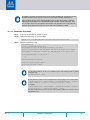
4.1.2 Downloading Mellanox OFED. . . . . . . . . . . . . . . . . . . . . . . . . . . . . . . . . . . . 28
4.1.3 Installing Mellanox OFED . . . . . . . . . . . . . . . . . . . . . . . . . . . . . . . . . . . . . . . 29
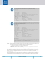
4.1.3.1 Installation Script . . . . . . . . . . . . . . . . . . . . . . . . . . . . . . . . . . . . . . . . . . . . . 29
4.1.3.2 Installation Procedure . . . . . . . . . . . . . . . . . . . . . . . . . . . . . . . . . . . . . . . . . 31
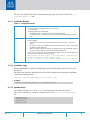
4.1.3.3 Installation Results . . . . . . . . . . . . . . . . . . . . . . . . . . . . . . . . . . . . . . . . . . . 33
4.1.3.4 Installation Logging . . . . . . . . . . . . . . . . . . . . . . . . . . . . . . . . . . . . . . . . . . . 33
4.1.3.5 openibd Script . . . . . . . . . . . . . . . . . . . . . . . . . . . . . . . . . . . . . . . . . . . . . . . 33
4.1.3.6 Driver Load Upon System Boot. . . . . . . . . . . . . . . . . . . . . . . . . . . . . . . . . . 34
4.1.3.7 mlnxofedinstall Return Codes. . . . . . . . . . . . . . . . . . . . . . . . . . . . . . . . . . . 34
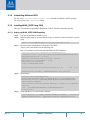
4.1.4 Uninstalling Mellanox OFED . . . . . . . . . . . . . . . . . . . . . . . . . . . . . . . . . . . . . 34
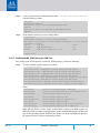
4.1.5 Installing MLNX_OFED Using YUM. . . . . . . . . . . . . . . . . . . . . . . . . . . . . . . . 35
4.1.5.1 Setting up MLNX_OFED YUM Repository . . . . . . . . . . . . . . . . . . . . . . . . . 35
4.1.5.2 Installing MLNX_OFED Using the YUM Tool . . . . . . . . . . . . . . . . . . . . . . . 36
4.1.5.3 Uninstalling Mellanox OFED Using the YUM Tool. . . . . . . . . . . . . . . . . . . 37
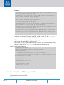
4.1.5.4 Installing MLNX_OFED Using apt-get Tool. . . . . . . . . . . . . . . . . . . . . . . . . 38
4.1.5.5 Setting up MLNX_OFED apt-get Repository . . . . . . . . . . . . . . . . . . . . . . . 38
4.1.5.6 Installing MLNX_OFED Using the apt-get Tool . . . . . . . . . . . . . . . . . . . . . 38
4.1.5.7 Uninstalling Mellanox OFED Using the apt-get Tool. . . . . . . . . . . . . . . . . 39
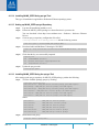
4.1.6 Updating Firmware After Installation . . . . . . . . . . . . . . . . . . . . . . . . . . . . . 39
4.1.6.1 Updating the Device Online . . . . . . . . . . . . . . . . . . . . . . . . . . . . . . . . . . . . 39
4.1.6.2 Updating the Device Manually . . . . . . . . . . . . . . . . . . . . . . . . . . . . . . . . . . 40
4.1.6.3 Updating the Device Firmware Automatically upon System Boot . . . . . 40
4.1.7 UEFI Secure Boot. . . . . . . . . . . . . . . . . . . . . . . . . . . . . . . . . . . . . . . . . . . . . . 40
4.1.7.1 Enrolling Mellanox's x.509 Public Key On your Systems . . . . . . . . . . . . . 41
4.1.7.2 Removing Signature from kernel Modules . . . . . . . . . . . . . . . . . . . . . . . . 41
4.1.8 Performance Tuning . . . . . . . . . . . . . . . . . . . . . . . . . . . . . . . . . . . . . . . . . . . 42
4.2 Windows Driver . . . . . . . . . . . . . . . . . . . . . . . . . . . . . . . . . . . . . . . . . . . . . . 43
4.2.1 Hardware and Software Requirements. . . . . . . . . . . . . . . . . . . . . . . . . . . . 43
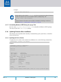
4.2.2 Downloading Mellanox WinOF-2 Driver . . . . . . . . . . . . . . . . . . . . . . . . . . . 43
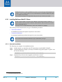
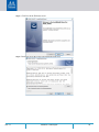
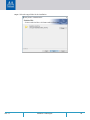
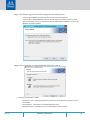
4.2.3 Installing Mellanox WinOF-2 Driver. . . . . . . . . . . . . . . . . . . . . . . . . . . . . . . 44
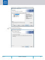
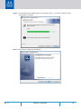
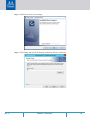
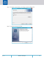
4.2.3.1 Attended Installation. . . . . . . . . . . . . . . . . . . . . . . . . . . . . . . . . . . . . . . . . . 44
4.2.3.2 Unattended Installation . . . . . . . . . . . . . . . . . . . . . . . . . . . . . . . . . . . . . . . 50
4.2.4 Installation Results . . . . . . . . . . . . . . . . . . . . . . . . . . . . . . . . . . . . . . . . . . . . 50
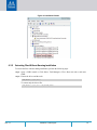
4.2.5 Extracting Files Without Running Installation. . . . . . . . . . . . . . . . . . . . . . . 51
4.2.6 Uninstalling Mellanox WinOF-2 Driver . . . . . . . . . . . . . . . . . . . . . . . . . . . . 54
4.2.6.1 Attended Uninstallation . . . . . . . . . . . . . . . . . . . . . . . . . . . . . . . . . . . . . . . 54
4.2.6.2 Unattended Uninstallation . . . . . . . . . . . . . . . . . . . . . . . . . . . . . . . . . . . . . 54
4.2.7 Firmware Upgrade . . . . . . . . . . . . . . . . . . . . . . . . . . . . . . . . . . . . . . . . . . . . 54

Rev 1.7 5Mellanox Technologies
4.2.8 Deploying the Driver on a Nano Server. . . . . . . . . . . . . . . . . . . . . . . . . . . . 54
4.2.8.1 Offline Installation . . . . . . . . . . . . . . . . . . . . . . . . . . . . . . . . . . . . . . . . . . . . 54
4.2.8.2 Online Update . . . . . . . . . . . . . . . . . . . . . . . . . . . . . . . . . . . . . . . . . . . . . . . 55
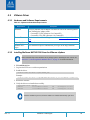
4.3 VMware Driver . . . . . . . . . . . . . . . . . . . . . . . . . . . . . . . . . . . . . . . . . . . . . . . 56
4.3.1 Hardware and Software Requirements. . . . . . . . . . . . . . . . . . . . . . . . . . . . 56
4.3.2 Installing Mellanox NATIVE ESXi Driver for VMware vSphere. . . . . . . . . . 56
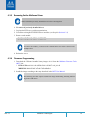
4.3.3 Removing Earlier Mellanox Driver . . . . . . . . . . . . . . . . . . . . . . . . . . . . . . . . 57
4.3.4 Firmware Programming . . . . . . . . . . . . . . . . . . . . . . . . . . . . . . . . . . . . . . . . 57
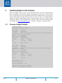
Chapter 5 Updating Adapter Card Firmware. . . . . . . . . . . . . . . . . . . . . . . . . . 58
5.1 Firmware Update Example . . . . . . . . . . . . . . . . . . . . . . . . . . . . . . . . . . . . . 58
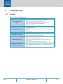
Chapter 6 Troubleshooting. . . . . . . . . . . . . . . . . . . . . . . . . . . . . . . . . . . . . . . . 59
6.1 General . . . . . . . . . . . . . . . . . . . . . . . . . . . . . . . . . . . . . . . . . . . . . . . . . . . . . 59
6.2 Linux. . . . . . . . . . . . . . . . . . . . . . . . . . . . . . . . . . . . . . . . . . . . . . . . . . . . . . . . 60
6.3 Windows . . . . . . . . . . . . . . . . . . . . . . . . . . . . . . . . . . . . . . . . . . . . . . . . . . . . 61
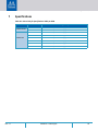
Chapter 7 Specifications . . . . . . . . . . . . . . . . . . . . . . . . . . . . . . . . . . . . . . . . . . 62
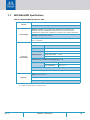
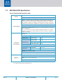
7.1 MCX516A-BDAT Specifications . . . . . . . . . . . . . . . . . . . . . . . . . . . . . . . . . . 63
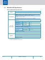
7.2 MCX516A-CDAT Specifications . . . . . . . . . . . . . . . . . . . . . . . . . . . . . . . . . . 64
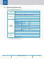
7.3 MCX512A-ACAT Specifications . . . . . . . . . . . . . . . . . . . . . . . . . . . . . . . . . . 65
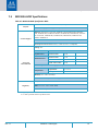
7.4 MCX512F-ACAT Specifications. . . . . . . . . . . . . . . . . . . . . . . . . . . . . . . . . . . 66
7.5 MCX515A-GCAT Specifications . . . . . . . . . . . . . . . . . . . . . . . . . . . . . . . . . . 67
7.6 MCX516A-GCAT Specifications . . . . . . . . . . . . . . . . . . . . . . . . . . . . . . . . . . 68
7.7 MCX515A-CCAT Specifications . . . . . . . . . . . . . . . . . . . . . . . . . . . . . . . . . . 69
7.8 MCX516A-CCAT Specifications . . . . . . . . . . . . . . . . . . . . . . . . . . . . . . . . . . 70
7.9 Airflow Specifications . . . . . . . . . . . . . . . . . . . . . . . . . . . . . . . . . . . . . . . . . . 71
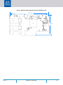
7.10 Board Mechanical Drawing and Dimensions . . . . . . . . . . . . . . . . . . . . . . . 72
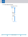
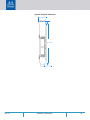
7.11 Bracket Mechanical Drawing . . . . . . . . . . . . . . . . . . . . . . . . . . . . . . . . . . . . 74
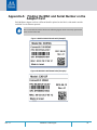
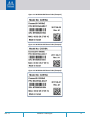
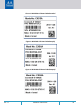
Appendix A Finding the MAC and Serial Number on the Adapter Card . . . . 76
Appendix B Safety Warnings . . . . . . . . . . . . . . . . . . . . . . . . . . . . . . . . . . . . . . 79
B.1 Safety Warnings in English . . . . . . . . . . . . . . . . . . . . . . . . . . . . . . . . . . . 79
B.2 Avertissements de sécurité d’installation (Warnings in French) . . . . . 81
B.3 Sicherheitshinweise (Warnings in German) . . . . . . . . . . . . . . . . . . . . . 83
B.4 Advertencias de seguridad para la instalación (Warnings in Spanish) 85

Rev 1.7 6Mellanox Technologies
List of Tables
Table 1: Revision History Table . . . . . . . . . . . . . . . . . . . . . . . . . . . . . . . . . . . . . . . . . . . . . . . . . 8
Table 2: Documents List. . . . . . . . . . . . . . . . . . . . . . . . . . . . . . . . . . . . . . . . . . . . . . . . . . . . . . . 9
Table 3: ConnectX-5 and ConnectX-5 Ex Ordering Part Numbers . . . . . . . . . . . . . . . . . . . . 11
Table 4: ConnectX-5 Ex Ethernet Adapter Cards . . . . . . . . . . . . . . . . . . . . . . . . . . . . . . . . . 12
Table 5: ConnectX-5 Ethernet Adapter Cards . . . . . . . . . . . . . . . . . . . . . . . . . . . . . . . . . . . . 12
Table 6: ConnectX-5 Package Contents . . . . . . . . . . . . . . . . . . . . . . . . . . . . . . . . . . . . . . . . . 12
Table 7: Features . . . . . . . . . . . . . . . . . . . . . . . . . . . . . . . . . . . . . . . . . . . . . . . . . . . . . . . . . . . 13
Table 8: PCI Express Interface . . . . . . . . . . . . . . . . . . . . . . . . . . . . . . . . . . . . . . . . . . . . . . . . . 15
Table 9: Physical and Logical Link Indications (Ethernet Mode). . . . . . . . . . . . . . . . . . . . . . 16
Table 10: ConnectX-5 Adapter Card Installation Procedure . . . . . . . . . . . . . . . . . . . . . . . . . . 17
Table 11: Airflow Color Legend . . . . . . . . . . . . . . . . . . . . . . . . . . . . . . . . . . . . . . . . . . . . . . . . . 18
Table 12: Hardware and Software Requirements . . . . . . . . . . . . . . . . . . . . . . . . . . . . . . . . . . 28
Table 13: Installation Results. . . . . . . . . . . . . . . . . . . . . . . . . . . . . . . . . . . . . . . . . . . . . . . . . . . 33
Table 14: mlnxofedinstall Return Codes. . . . . . . . . . . . . . . . . . . . . . . . . . . . . . . . . . . . . . . . . . 34
Table 15: Hardware and Software Requirements . . . . . . . . . . . . . . . . . . . . . . . . . . . . . . . . . . 43
Table 16: Software and Hardware Requirements . . . . . . . . . . . . . . . . . . . . . . . . . . . . . . . . . . 56
Table 17: General Troubleshooting. . . . . . . . . . . . . . . . . . . . . . . . . . . . . . . . . . . . . . . . . . . . . . 59
Table 18: Linux Troubleshooting . . . . . . . . . . . . . . . . . . . . . . . . . . . . . . . . . . . . . . . . . . . . . . . . 60
Table 19: Windows Troubleshooting . . . . . . . . . . . . . . . . . . . . . . . . . . . . . . . . . . . . . . . . . . . . 61
Table 20: Direct links for Specifications Table per OPN . . . . . . . . . . . . . . . . . . . . . . . . . . . . . 62
Table 21: MCX516A-BDAT Specification Table . . . . . . . . . . . . . . . . . . . . . . . . . . . . . . . . . . . . 63
Table 22: MCX516A-CDAT Specification Table . . . . . . . . . . . . . . . . . . . . . . . . . . . . . . . . . . . . 64
Table 23: MCX512A-ACAT Specification Table . . . . . . . . . . . . . . . . . . . . . . . . . . . . . . . . . . . . 65
Table 24: MCX512F-ACAT Specification Table . . . . . . . . . . . . . . . . . . . . . . . . . . . . . . . . . . . . 66
Table 25: MCX515A-GCAT Specification Table . . . . . . . . . . . . . . . . . . . . . . . . . . . . . . . . . . . . 67
Table 26: MCX516A-GCAT Specification Table . . . . . . . . . . . . . . . . . . . . . . . . . . . . . . . . . . . . 68
Table 27: MCX515A-CCAT Specification Table . . . . . . . . . . . . . . . . . . . . . . . . . . . . . . . . . . . . 69
Table 28: MCX516A-CCAT Specification Table . . . . . . . . . . . . . . . . . . . . . . . . . . . . . . . . . . . . 70
Table 29: Airflow Specifications . . . . . . . . . . . . . . . . . . . . . . . . . . . . . . . . . . . . . . . . . . . . . . . . 71

Rev 1.7 7Mellanox Technologies
List of Figures
Figure 1: EMI Fingers on QSFP28 Connector . . . . . . . . . . . . . . . . . . . . . . . . . . . . . . . . . . . . . . . . . . . . 20
Figure 2: Plastic Ziplock . . . . . . . . . . . . . . . . . . . . . . . . . . . . . . . . . . . . . . . . . . . . . . . . . . . . . . . . . . . . . 20
Figure 3: PCI Device (Example) . . . . . . . . . . . . . . . . . . . . . . . . . . . . . . . . . . . . . . . . . . . . . . . . . . . . . . . 26
Figure 4: Installation Results . . . . . . . . . . . . . . . . . . . . . . . . . . . . . . . . . . . . . . . . . . . . . . . . . . . . . . . . 51
Figure 5: Mechanical Drawing of Dual-port x16 Adapter Cards . . . . . . . . . . . . . . . . . . . . . . . . . . . . 72
Figure 6: Mechanical Drawing of the Dual-port x8 Adapter Card . . . . . . . . . . . . . . . . . . . . . . . . . . . 73
Figure 7: Single-port Tall Bracket . . . . . . . . . . . . . . . . . . . . . . . . . . . . . . . . . . . . . . . . . . . . . . . . . . . . . 74
Figure 8: Dual-port Tall Bracket . . . . . . . . . . . . . . . . . . . . . . . . . . . . . . . . . . . . . . . . . . . . . . . . . . . . . . 75
Figure 9: MCX512A-ACAT Board Label (Example) . . . . . . . . . . . . . . . . . . . . . . . . . . . . . . . . . . . . . . . 76
Figure 10: MCX512F-ACAT Board Label (Example) . . . . . . . . . . . . . . . . . . . . . . . . . . . . . . . . . . . . . . . . 76
Figure 11: MCX516A-BDAT Board Label (Example) . . . . . . . . . . . . . . . . . . . . . . . . . . . . . . . . . . . . . . . 77
Figure 12: MCX515A-GCAT Board Label (Example) . . . . . . . . . . . . . . . . . . . . . . . . . . . . . . . . . . . . . . . 77
Figure 13: MCX516A-GCAT Board Label (Example) . . . . . . . . . . . . . . . . . . . . . . . . . . . . . . . . . . . . . . . 77
Figure 14: MCX515A-CCAT Board Label (Example) . . . . . . . . . . . . . . . . . . . . . . . . . . . . . . . . . . . . . . . 78
Figure 15: MCX516A-CCAT Board Label Example) . . . . . . . . . . . . . . . . . . . . . . . . . . . . . . . . . . . . . . . . 78
Figure 16: MCX516A-CDAT Board Label (Example) . . . . . . . . . . . . . . . . . . . . . . . . . . . . . . . . . . . . . . . 78

Rev 1.7 8Mellanox Technologies
Revision History
This document was printed on November 11, 2018.
Table 1 - Revision History Table
Date Rev Comments/Changes
November 2018 1.7 Added MCX512F-ACAT and MCX512A-ACAT support across document and
added the following:
• Product Overview on page 12
• MCX512A-ACAT Specifications on page 65
• MCX512F-ACAT Specifications on page 66
January 2018 1.6 • Added a note to System Requirements on page 18.
November 2017 1.5 • Updated Adapter Card LED Operations on page 72
September 2017 1.4 • Added MCX516A-BDAT support across document and added the following:
• MCX516A-BDAT Specifications on page 63
• MCX512A-ACAT Board Label (Example) on page 76.
• Updated the following sections:
• Linux on page 28
• MCX515A-GCAT Specification Table on page 67
• MCX516A-GCAT Specification Table on page 68
• MCX515A-CCAT Specifications on page 69
• MCX516A-CCAT Specifications on page 70
• Airflow Specifications on page 71
August 2017 1.3 • Added MCX515A-GCAT and MCX516A-GCAT support across document and
added the following:
• MCX516A-BDAT Specifications on page 63
• MCX516A-GCAT Specification Table on page 68
• Single-port Tall Bracket on page 74
• MCX512A-ACAT Board Label (Example) on page 76
• MCX516A-GCAT Board Label (Example) on page 77
• Updated the following specifications tables:
• MCX515A-CCAT Specifications on page 69
• MCX516A-CCAT Specifications on page 70
• MCX516A-CDAT Specifications on page 64
July 2017 1.2 • Updated the following specifications tables:
• MCX515A-CCAT Specifications on page 69
• MCX516A-CCAT Specifications on page 70
• MCX516A-CDAT Specifications on page 64
• Updated Airflow Specifications on page 71
April 2017 1.1 • Updated Product Overview on page 12
• Updated Installation Instructions on page 21
March 2017 1.0 First release

Rev 1.7 9Mellanox Technologies
About This Manual
This User Manual describes Mellanox Technologies ConnectX®-5 and ConnectX®-5 Ex Ether-
net Single and Dual SFP28 and QSFP28 port PCI Express x8/x16 adapter cards. It provides
details as to the interfaces of the board, specifications, required software and firmware for operat
-
ing the board, and relevant documentation.
Intended Audience
This manual is intended for the installer and user of these cards.
The manual assumes basic familiarity with Ethernet network and architecture specifications.
Related Documentation
Table 2 - Documents List
Mellanox Firmware Tools (MFT) User Manual
Document no. 2204UG
User Manual describing the set of MFT firmware management
tools for a single node.
See http://www.mellanox.com => Products => Software =>
Firmware Tools
Mellanox Firmware Utility (mlxup) User Manual
and Release Notes
Mellanox firmware update and query utility used to update the
firmware.
See http://www.mellanox.com => Products => Software =>
Firmware Tools => mlxup Firmware Utility
Mellanox OFED for Linux
User Manual
Document no. 2877
User Manual describing OFED features, performance, Band
diagnostic, tools content and configuration.
See http://www.mellanox.com => Products => Software =>
Ethernet Drivers=> Mellanox OpenFabrics Enterprise Distribu-
tion for Linux (MLNX_OFED)
Mellanox OFED for Linux Release Notes
Document no. 2877
Release Notes for Mellanox OFED for Linux driver kit for Mel-
lanox adapter cards:
See: http://www.mellanox.com =>Products => Software =>
Ethernet Drivers => Linux SW/Drivers => Release Notes
WinOF-2 for Windows
User Manual
Document no. MLX-15-3280
User Manual describing WinOF-2 features, performance, Ether-
net diagnostic, tools content and configuration.
See http://www.mellanox.com => Products => Software =>
Windows SW/Drivers
Mellanox OFED for Windows Driver
Release Notes
Release notes for Mellanox Technologies' MLNX_EN for Linux
driver kit for Mellanox adapter cards:
See http://www.mellanox.com => Products => Software =>
Ethernet Drivers => Mellanox OFED for Windows => WinOF-
2 Release Notes
Mellanox VMware for Ethernet User Manual
Document no. MLNX-15-4896
User Manual describing the various components of the Mella-
nox ConnectX® NATIVE ESXi stack: See => http://www.mel-
lanox.com Products => Software => Ethernet Drivers =>
VMware Driver => User Manual
Mellanox VMware for Ethernet Release Notes Release notes for Mellanox ConnectX® NATIVE ESXi stack:
See => http://www.mellanox.com Software => Ethernet Drivers
=> VMware Driver => Release Notes

Rev 1.7 10Mellanox Technologies
Document Conventions
When discussing memory sizes, MB and MBytes are used in this document to mean size in mega
Bytes. The use of Mb or Mbits (small b) indicates size in mega bits. In this document PCIe is
used to mean PCI Express.
Technical Support
Customers who purchased Mellanox products directly from Mellanox are invited to contact us
through the following methods.
•URL: http://www.mellanox.com => Support
• E-mail: support@mellanox.com
• Tel: +1.408.916.0055
Customers who purchased Mellanox M-1 Global Support Services, please see your contract for
details regarding Technical Support.
Customers who purchased Mellanox products through a Mellanox approved reseller should first seek
assistance through their reseller.

Introduction
Rev 1.7
11Mellanox Technologies
1 Introduction
This is the User Guide for Mellanox Technologies Ethernet adapter cards based on the Con-
nectX®-5 integrated circuit device. These adapters connectivity provide the highest performing
low latency and most flexible interconnect solution for PCI Express Gen 3.0/4.0 servers used in
Enterprise Data Centers and High-Performance Computing environments.
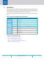
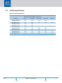
Table 3 provides the ordering part numbers (OPN) for the available ConnectX-5 Ethernet adapter
cards.
Table 3 - ConnectX-5 and ConnectX-5 Ex Ordering Part Numbers
This chapter covers the following topics:
• Section 1.1, “Product Overview”, on page 12
• Section 1.2, “Package Content”, on page 12
• Section 1.3, “Features and Benefits”, on page 13
• Section 1.4, “Operating Systems/Distributions”, on page 14
• Section 1.5, “Connectivity”, on page 14
OPN Marketing Description
ConnectX-5 Ex
MCX516A-BDAT ConnectX®-5 Ex EN network interface card, 40GbE dual-port QSFP28, PCIe Gen
4.0 x16, tall bracket
MCX516A-CDAT ConnectX®-5 Ex EN network interface card, 100GbE dual-port QSFP28, PCIe Gen
4.0 x16, tall bracket
ConnectX-5
MCX512A-ACAT ConnectX®-5 EN network interface card, 25GbE dual-port SFP28, PCIe Gen 3.0
x8, tall bracket
MCX512F-ACAT ConnectX®-5 EN network interface card, 25GbE Dual-port SFP28, PCIe Gen 3.0
x16, tall bracket
MCX515A-GCAT ConnectX®-5 EN network interface card, 50GbE single-port QSFP28, PCIe Gen
3.0 x16, tall bracket
MCX516A-GCAT ConnectX®-5 EN network interface card, 50GbE dual-port QSFP28, PCIe Gen 3.0
x16, tall bracket
MCX515A-CCAT ConnectX®-5 EN network interface card, 100GbE single-port QSFP28, PCIe Gen
3.0 x16, tall bracket
MCX516A-CCAT ConnectX®-5 EN network interface card, 100GbE dual-port QSFP28, PCIe Gen
3.0 x16, tall bracket

Introduction
Rev 1.7
12Mellanox Technologies
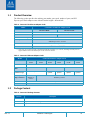
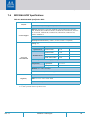
1.1 Product Overview
The following section provides the ordering part number, port speed, number of ports, and PCI
Express speed. Each adapter comes with two bracket heights - short and tall.
Table 4 - ConnectX-5 Ex Ethernet Adapter Cards
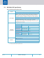
Table 5 - ConnectX-5 Ethernet Adapter Cards
1.2 Package Content
Table 6 - ConnectX-5 Package Contents
Model ConnectX-5 Ex Ethernet Adapter Cards
Part Number
MCX516A-BDAT
a
a. Note: PCIe 4.0 x16 bus can supply a maximum bandwidth of 256Gb/s (=16 *16GT/s, including overhead), and can
support 200Gb/s when both network ports of the card run at 100Gb/s.
MCX516A-CDAT
a
Dimensions 2.71 in. x 5.6 in. (68.90mm x 142.24 mm) – low profile
Ethernet Data Rate 1/10/25/40 Gb/s 10/25/40/50/100 Gb/s
Network Connector Type Dual-port QSFP28
PCI Express Connectors PCIe Gen 3.0/4.0 x16
SERDES @ 8.0GT/s / 16.0GT/s
RoHS RoHS Compliant
IC Part Number
MT28808A0-FCCF-EV
Model ConnectX-5 Ethernet Adapter Cards
Part Number MCX512A-
ACAT
MCX512F-
ACAT
MCX515A-
GCAT
MCX516A-
GCAT
MCX515A-
CCAT
MCX516A-
CCAT
Dimensions 2.71 in. x 5.6 in. (68.90mm x 142.24 mm) – low profile
Ethernet Data
Rate
1/10/25 Gb/s 10/25/40/50 Gb/s 10/25/40/50/100 Gb/s
Network
Connector Type
Dual-port SFP28 Single-port
QSFP28
Dual-port
QSFP28
Single-port
QSFP28
Dual-port
QSFP28
PCI Express
Edge Connectors
PCIe Gen 3.0 x8
SERDES @
8.0GT/s
PCIe Gen 3.0 x16
SERDES @ 8.0GT/s
RoHS RoHS Compliant
IC Part Number MT27808A0-FCCF-EV
Quantity Description
1 ConnectX-5 Adapter Card
1 Adapter card tall bracket (shipped assembled on the card)
1 Adapter card short bracket

Introduction
Rev 1.7
13Mellanox Technologies
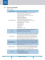
1.3 Features and Benefits
Table 7 - Features
a
PCI Express (PCIe)
Uses PCIe Gen 3.0 (8GT/s) and Gen 4.0 (16GT/s) through an x8 or x16 edge
connector. Gen 1.1 and 2.0 compatible.
Up to 100 Gigabit Ethernet
Mellanox adapters comply with the following IEEE 802.3 standards:
– 100GbE/ 50GbE / 40GbE / 25GbE / 10GbE / 1GbE
– IEEE 802.3bj, 802.3bm 100 Gigabit Ethernet
– IEEE 802.3by, Ethernet Consortium25, 50 Gigabit Ethernet,
supporting all FEC modes
– IEEE 802.3ba 40 Gigabit Ethernet
– IEEE 802.3by 25 Gigabit Ethernet
– IEEE 802.3ae 10 Gigabit Ethernet
– IEEE 802.3ap based auto-negotiation and KR startup
– Proprietary Ethernet protocols (20/40GBASE-R2, 50GBASE-R4)
– IEEE 802.3ad, 802.1AX Link Aggregation
– IEEE 802.1Q, 802.1P VLAN tags and priority
– IEEE 802.1Qau (QCN)
– Congestion Notification
– IEEE 802.1Qaz (ETS)
– IEEE 802.1Qbb (PFC)
– IEEE 802.1Qbg
– IEEE 1588v2
– Jumbo frame support (9.6KB)
Memory
PCI Express - stores and accesses Ethernet fabric connection information and
packet data.SPI Quad - includes 128Mbit SPI Quad Flash device
(W25Q128FVSIG device by ST Microelectronics)
VPD EEPROM - The EEPROM capacity is 128Kbit.
Overlay Networks
In order to better scale their networks, data center operators often create overlay
networks that carry traffic from individual virtual machines over logical tunnels
in encapsulated formats such as NVGRE and VXLAN. While this solves net
-
work scalability issues, it hides the TCP packet from the hardware offloading
engines, placing higher loads on the host CPU. ConnectX-5 effectively
addresses this by providing advanced NVGRE and VXLAN hardware offload
-
ing engines that encapsulate and de-capsulate the overlay protocol.
RDMA and RDMA over
Converged Ethernet (RoCE)
ConnectX-5, utilizing IBTA RDMA (Remote Data Memory Access) and RoCE
(RDMA over Converged Ethernet) technology, delivers low-latency and high-
performance over Band and Ethernet networks. Leveraging data center bridging
(DCB) capabilities as well as ConnectX-5 advanced congestion control hard
-
ware mechanisms, RoCE provides efficient low-latency RDMA services over
Layer 2 and Layer 3 networks.
Mellanox PeerDirect™
PeerDirect™ communication provides high efficiency RDMA access by elimi-
nating unnecessary internal data copies between components on the PCIe bus
(for example, from GPU to CPU), and therefore significantly reduces applica
-
tion run time. ConnectX-5 advanced acceleration technology enables higher
cluster efficiency and scalability to tens of thousands of nodes.
CPU Offload
Adapter functionality enabling reduced CPU overhead allowing more available
CPU for computation tasks.
Open VSwitch (OVS) offload using ASAP
2(TM)
• Flexible match-action flow tables
• Tunneling encapsulation / decapsulation

Introduction
Rev 1.7
14Mellanox Technologies
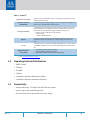
1.4 Operating Systems/Distributions
• RHEL/CentOS
•Windows
• FreeBSD
•VMware
• OpenFabrics Enterprise Distribution (OFED)
• OpenFabrics Windows Distribution (WinOF-2)
1.5 Connectivity
• Interoperable with 1/10/25/40/50/100 Gb/s Ethernet switches
• Passive copper cable with ESD protection
• Powered connectors for optical and active cable support
Quality of Service (QoS)
Support for port-based Quality of Service enabling various application require-
ments for latency and SLA.
Hardware-based I/O
Virtualization
ConnectX-5 provides dedicated adapter resources and guaranteed isolation and
protection for virtual machines within the server.
Storage Acceleration
A consolidated compute and storage network achieves significant cost-perfor-
mance advantages over multi-fabric networks. Standard block and file access
protocols can leverage RDMA for high-performance storage access.
• NVMe over Fabric offloads for target machine
• Erasure Coding
• T10-DIF Signature Handover
SR-IOV
ConnectX-5 SR-IOV technology provides dedicated adapter resources and
guaranteed isolation and protection for virtual machines (VM) within the
server.
NC-SI
The adapter supports a Network Controller Sideband Interface (NC-SI), MCTP
over SMBus and MCTP over PCIe - Baseboard Management Controller inter-
face.
High-Performance
Accelerations
• Tag Matching and Rendezvous Offloads
• Adaptive Routing on Reliable Transport
• Burst Buffer Offloads for Background Checkpointing
a. This section describes hardware features and capabilities. Please refer to the driver release notes for feature availabil-
ity. See “Related Documentation” on page 9.
.
Table 7 - Features
a

Interfaces
Rev 1.7
15Mellanox Technologies
2 Interfaces
Each adapter card includes the following interfaces:
• “Ethernet SFP28 and QSFP28 Interface”
• “PCI Express Interface”
• “LED Interface”
• “Heatsink Interface”
• “SMBus Interface”
• “Voltage Regulators”
2.1 Ethernet SFP28 and QSFP28 Interface
The network ports of the ConnectX®-5 adapter card are compliant with the IEEE 802.3 Ethernet
standards listed in
Table 7. Ethernet traffic is transmitted through the cards' SFP28 and QSFP28
connectors.
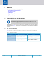
2.2 PCI Express Interface
Table 8 describes the supported PCIe interface in ConnectX-5 and ConnectX-5 Ex adapter cards.
Table 8 - PCI Express Interface
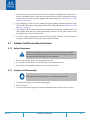
Please note that the adapter card includes special circuits to protect the card/server from
ESD shocks when plugging copper cables.
ConnectX-5 Supported PCIe Interface Features
ConnectX-5
PCIe Gen 3.0 (1.1 and 2.0 compatible)
through x8 or x16 edge connectors
Link Rates: 2.5. 5.0 or 8.0GT/s
Auto Negotiation to: x16, x8, x4, x2 or x1
Support for MSI/MSI-X mechanisms
ConnectX-5 Ex
PCIe Gen 3.0/4.0 (1.1 and 2.0 compati-
ble) through x16 edge connectors
Link Rates: 2.5. 5.0, 8.0 or 16.0GT/s
Auto Negotiation to: x16, x8, x4, x2 or x1
Support for MSI/MSI-X mechanisms

Interfaces
Rev 1.7
16Mellanox Technologies
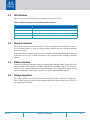
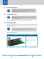
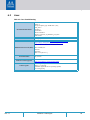
2.3 LED Interface
There is one bi-color I/O LED per port to indicate link status. See Table 9.
Table 9 - Physical and Logical Link Indications (Ethernet Mode)
2.4 Heatsink Interface
The heatsink is attached to the ConnectX-5 IC in order to dissipate the heat from the ConnectX-5
IC. It is attached either by using four spring-loaded push pins that insert into four mounting
holes, or by screws.
ConnectX-5 IC has a thermal shutdown safety mechanism which automatically shuts down the
ConnectX-5 card in cases of high temperature event, improper thermal coupling or heatsink
removal.
2.5 SMBus Interface
ConnectX-5 technology maintains support for manageability through a BMC. ConnectX-5 PCIe
stand-up adapter can be connected to a BMC using MCTP over SMBus or MCTP over PCIe pro
-
tocols as if it is a standard Mellanox PCIe stand-up adapter. For configuring the adapter for the
specific manageability solution in use by the server, please contact Mellanox Support.
2.6 Voltage Regulators
The voltage regulator power is derived from the PCI Express edge connector 12V supply pins.
These voltage supply pins feed on-board regulators that provide the necessary power to the vari
-
ous components on the card.
LED Color and State Description
Off A link has not been established
Blinking Amber
a
a. 1 Hz Blinking Amber occurs due to running a beacon command for locating the adapter card.
4 Hz blinking Amber indicates a problem with the link
Solid Green Indicates a valid link with no active traffic
Blinking Green Indicates a valid logical link with active traffic

Hardware Installation
Rev 1.7
17Mellanox Technologies
3 Hardware Installation
Installation and initialization of ConnectX-5 adapter cards require attention to the mechanical
attributes, power specification, and precautions for electronic equipment.
Installation Procedure Overview
The installation procedure of ConnectX-5 adapter cards involve the following phases:
Table 10 - ConnectX-5 Adapter Card Installation Procedure
Step Procedure Direct Link
1 Check the system’s hardware and software requirements. Refer to “System Requirements”
2
Pay attention to the airflow consideration within the host
system
Refer to “Airflow Requirements”
3 Follow the safety precautions Refer to “Safety Precautions”
4 Follow the pre-installation check list Refer to “Pre-Installation Checklist”
5
(Optional) Replace the full-height mounting bracket
with the supplied short bracket
Refer to “Bracket Replacement Instructions”
6 Install ConnectX-5 adapter card in the system Refer to “Installation Instructions”
7 Connect cables or modules to the card Refer to “Cables and Modules”
8 Identify ConnectX-5 adapter card in the system Refer to “Identify the Card in Your System”

Hardware Installation
Rev 1.7
18Mellanox Technologies
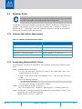
3.1 System Requirements
3.1.1 Hardware Requirements
A system with a PCI Express x8 or x16 slot is required for installing the card.
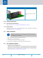
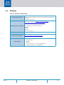
3.1.2 Airflow Requirements
ConnectX-5 adapter cards are offered with two airflow patterns: from the heatsink to the network
ports and vice versa.
Table 11 provides an airflow color legend. Please refer to “Specifications” for
airflow numbers per OPN.
Table 11 - Airflow Color Legend
Unless otherwise specified, Mellanox products are designed to work in an environmentally
controlled data center with low levels of gaseous and dust (particulate) contamination.
The operation environment should meet severity level G1 as per ISA 71.04 for gaseous con-
tamination and ISO 14644-1 class 8 for cleanliness level.
For proper operation and performance, please make sure to use a PCIe x8 or x16 slot that can
supply sufficient power to your card. Refer to Section 7.9, “Airflow Specifications”, on page 71
for more power requirements.
All cards in the system should be planned with the same airflow direction.
Direction Description
From the heatsink to the network
ports

Hardware Installation
Rev 1.7
19Mellanox Technologies
3.1.3 Software Requirements
3.1.3.1 Operating Systems/Distributions
Please refer to Section 1.4, “Operating Systems/Distributions”, on page 14.
3.1.3.2 Software Stacks
Mellanox OpenFabric software package MLNX_OFED for Linux, and WinOF-2 for Windows
and VMware. See
Chapter 4, “Driver Installation”.
3.2 Safety Precautions
1. Remove any metallic objects from your hands and wrists.
2. Make sure to use only insulated tools.
3. Verify that the system is powered off and is unplugged.
4. It is strongly recommended to use an ESD strap or other antistatic devices.
3.3 Pre-Installation Checklist
1. Unpack the ConnectX-5 adapter card
Unpack and remove the ConnectX-5 card. Check against the package contents list that all the
parts have been sent. Check the parts for visible damage that may have occurred during ship
-
ping. Please note that the cards must be placed on an antistatic surface. For package contents
please refer to
Section 1.2, “Package Content”, on page 12.
From the network ports to the heat-
sink
The adapter is being installed in a system that operates with voltages that can be lethal.
Before opening the case of the system, observe the following precautions to avoid injury and
prevent damage to system components.
Direction Description

Hardware Installation
Rev 1.7
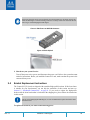
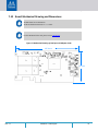
20Mellanox Technologies
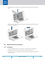
Figure 1: EMI Fingers on QSFP28 Connector
Figure 2: Plastic Ziplock
2. Shut down your system if active.
Turn off the power to the system, and disconnect the power cord. Refer to the system documen-
tation for instructions. Before you install the ConnectX-5 card, make sure that the system is dis-
connected from power.
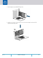
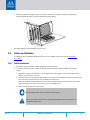
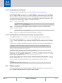
3.4 Bracket Replacement Instructions
The ConnectX-5 [Ex] cards are shipped with assembled high-profile brackets. If this form factor
is suitable for your requirements, you can skip the remainder of this section and move to
Section 3.5, “Installation Instructions”, on page 21. If you need to replace the high-profile
bracket with the short bracket that is included in the shipping box, please follow the instructions
in this section.
To replace the brackets you will need the following parts:
Please note that if the card is removed hastily from the antistatic bag, the plastic ziplock may
harm the EMI fingers on the networking connector. Carefully remove the card from the anti
-
static bag to avoid damaging the EMI fingers.
Due to risk of damaging the EMI fingers, it is not recommended to replace the bracket more
than three times.
Page is loading ...
Page is loading ...
Page is loading ...
Page is loading ...
Page is loading ...
Page is loading ...
Page is loading ...
Page is loading ...
Page is loading ...
Page is loading ...
Page is loading ...
Page is loading ...
Page is loading ...
Page is loading ...
Page is loading ...
Page is loading ...
Page is loading ...
Page is loading ...
Page is loading ...
Page is loading ...
Page is loading ...
Page is loading ...
Page is loading ...
Page is loading ...
Page is loading ...
Page is loading ...
Page is loading ...
Page is loading ...
Page is loading ...
Page is loading ...
Page is loading ...
Page is loading ...
Page is loading ...
Page is loading ...
Page is loading ...
Page is loading ...
Page is loading ...
Page is loading ...
Page is loading ...
Page is loading ...
Page is loading ...
Page is loading ...
Page is loading ...
Page is loading ...
Page is loading ...
Page is loading ...
Page is loading ...
Page is loading ...
Page is loading ...
Page is loading ...
Page is loading ...
Page is loading ...
Page is loading ...
Page is loading ...
Page is loading ...
Page is loading ...
Page is loading ...
Page is loading ...
Page is loading ...
Page is loading ...
Page is loading ...
Page is loading ...
Page is loading ...
Page is loading ...
Page is loading ...
Page is loading ...
-
 1
1
-
 2
2
-
 3
3
-
 4
4
-
 5
5
-
 6
6
-
 7
7
-
 8
8
-
 9
9
-
 10
10
-
 11
11
-
 12
12
-
 13
13
-
 14
14
-
 15
15
-
 16
16
-
 17
17
-
 18
18
-
 19
19
-
 20
20
-
 21
21
-
 22
22
-
 23
23
-
 24
24
-
 25
25
-
 26
26
-
 27
27
-
 28
28
-
 29
29
-
 30
30
-
 31
31
-
 32
32
-
 33
33
-
 34
34
-
 35
35
-
 36
36
-
 37
37
-
 38
38
-
 39
39
-
 40
40
-
 41
41
-
 42
42
-
 43
43
-
 44
44
-
 45
45
-
 46
46
-
 47
47
-
 48
48
-
 49
49
-
 50
50
-
 51
51
-
 52
52
-
 53
53
-
 54
54
-
 55
55
-
 56
56
-
 57
57
-
 58
58
-
 59
59
-
 60
60
-
 61
61
-
 62
62
-
 63
63
-
 64
64
-
 65
65
-
 66
66
-
 67
67
-
 68
68
-
 69
69
-
 70
70
-
 71
71
-
 72
72
-
 73
73
-
 74
74
-
 75
75
-
 76
76
-
 77
77
-
 78
78
-
 79
79
-
 80
80
-
 81
81
-
 82
82
-
 83
83
-
 84
84
-
 85
85
-
 86
86


Mellanox Technologies MCX512A-ACAT User manual
- Type
- User manual
- This manual is also suitable for
Ask a question and I''ll find the answer in the document
Finding information in a document is now easier with AI
Related papers
-
Mellanox Technologies 0NHYP5 User manual
-
Mellanox Technologies MCX4412-ACAN User manual
-
-
-
-
-
-
-
-
Other documents
-
Rosewill RC-20003 Installation guide
-
Rasonic RCM-F51WB User manual
-
Rosewill RC-NIC413 4 Port Gigabit Card User manual
-
Dell MCQH29-XDR User manual
-
Nvidia Mellanox ConnectX-6 Dx Series User manual
-
Asus PEM-FDR User manual
-
Broadcom NX1 Installation guide
-
Repotec RP-4010EX Owner's manual
-
 BrosTrend AC1L Wireless Network Adapter User manual
-
