
I - Ship ping and Pack ing List
Package 1 of 1 contains:
1 ea. Supply Down-flow Duct Cover Panel
1 ea. Return Down-flow Duct Cover Panel
1 ea. Horizontal Supply Conversion Panel
1 ea. Horizontal Return Conversion Panel
1 ea. Return Air Compartment, Filter Access Panel
1 ea. of the following Air Temperature Limit
* 626474 - 180
o
F Open temp, SPDT
* 626341 - 155
o
F Open temp, SPST
* 626575 - 125
o
F Open temp, SPDT
2 ea. Horizontal Conversion Panel Retaining Clips
6 ea. #10 x ½" Self drilling/tapping Screws
18 items Total
FORM# 279D-0309
Warn ing:
v Improper installation, adjustment, alteration, service or maintenance can cause injury or property damage.
v Refer to these instructions for the proper application of this accessory kit.
v For assistance or additional information consult a qualified, professional installer or service agency.
II - Ap pli ca tion
This kit is for use on Nordyne R6GP Series Packaged Gas/Electric units in the short cabinet (43.5” tall with baserails) and
will provide a means to convert factory standard units from the down-flow supply & return duct setup to a horizontal supply
& return duct configuration. When installing this accessory kit in conjunction with other accessory kits, it is recommended
to install this kit first.
Notice to Installer - Depending on the R6 unit model, the air temperature, safety limit switches may need to be replaced in
order to properly configure the unit for safe operation. The first step of this installation is the determination of the units’
model number and installed heat-exchanger configuration. The second step is the determination of the required safety
limits for the safe operation of the unit. Failure to comply with these procedures will void the warranty of the appliance may
cause personnel injury or property damage.
III - In stal la tion Procedures
1. Determine unit cooling capacity and the installed heat exchanger.
2. Determine the safety limits required for horizontal operation.
3. Perform the installation as described in section 4.
4. Record the information required on the back cover of these instructions.
5. Save these instructions in a safe place, along with the unit installation instructions for future reference with the
equipment owner.
INSTALLATION
INSTRUCTION
INSTALLATION INSTRUCTIONS FOR
HORIZONTAL AIR DISCHARGE KIT
559914
R6GP SERIES 6 & 7 ½ TON EQUIPMENT
Check contents for shipping damage. Contact the last carrier immediately if any shipping damage is found.
These instructions are intended primarily to assist qualified individuals, experienced in the proper installation of this
appliance. Some local codes require licensed installation/service personnel for this type of equipment. Read all
instructions carefully before starting the installation. Read these instructions thoroughly before starting the installation.
Follow all precautions and warnings contained within these instructions and on the unit.
30
16.5
30
16.5

INSTALLATION
INSTRUCTION
INSTALLATION INSTRUCTIONS FOR
HORIZONTAL AIR DISCHARGE KIT
559914
R6GP SERIES 6 & 7 ½ TON EQUIPMENT
IV - In stal la tion In struc tions
1. Refer to the rating plate installed on the unit, record the model number, located at the top of the rating plate on the
installation checklist located on the back cover of these instructions. Determine the unit cooling capacity and heat
exchanger size using the model number decode below:
R6GP-072 C-100 C 0001
Factory Configuration Code,
not applicable to all units, may not be shown
Indicates the installation type, a “C” indicates the unit
is to be installed in North America (USA/Canada)
Indicates the input capacity of the gas heat exchanger for
natural gas at sea level in thousands of Btu/hr
Indicates unit input voltage configuration.
(Not applicable to complete these instructions.)
Indicates the cooling capacity in thousands of Btu/hr
(e.g. 072 = 72,000 Btuh -or- 72 kBtuh)
Indicates unit model type
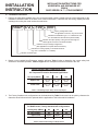
2. Based on the installed Heat Exchanger capacity reference Table 1 below to determine the correct safety limit
switches for horizontal operation. Refer to Figure 4 for a description of the limit locations in the unit.
3. The Factory Standard unit configurations can be determined by Table 2 below and can be quickly referenced to
determine what limits need to be replaced with the application of this horizontal kit installation.
Hor i zon tal Lim its Con ver sion Re quire ments
For R6GP Se ries, Fac tory Stan dard Unit Con fig u ra tions
Cooling Cap. (kBtuh)
090 072 072
HX, Input (kBtuh)
200 166 100
Up per Limit
Replace Replace No Change
Lower Limit
Replace No Change No Change
Table 2. Standard Limit Change-out Requirements
R6GP Se ries Light Com mer cial Units
Heat Exchangers with 100k - 200k Btuh in puts
Air Tem per a ture Lim its for Hor i zon tal Ap pli ca tions
HX, Input (kBtuh)
200 166 100
Up per Limit
125
o
/ 85
o
626575
155
o
/ 115
o
626341
135
o
/ 95
o
626583
Lower Limit
180
o
/ 140
o
626474
255
o
/ 215
o
626582
255
o
/ 215
o
626582
Table 1. Limit Settings: Open Temp / Close Temp (deg F)

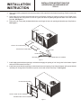
Figure 1
FILTERS
SUPPLY
RETURN
SUP PLY AIR COVER PANEL
COVER PANEL
UNIT BASE
LIPS UNDER BACK OF OPENING
Figure 2
4. Remove the existing supply and return access panels of unit to provide for horizontal air openings. Retain screws to be
used later.
5. Place supply air cover panel (insulated side down) over flanges of supply air opening in bottom of unit. Fasten cover
panel to flanges and, using holes in cover as a guide, drill holes in opening flanges and attach cover with screws
provided. See Figure 1.
6. Place return air cover panel (insulated side down) over flanges of return air opening and attach as per Step 5 above.
See Figure 1.
INSTALLATION
INSTRUCTION
INSTALLATION INSTRUCTIONS FOR
HORIZONTAL AIR DISCHARGE KIT
559914
7. Install supply panel with duct opening to unit horizontal supply air opening of unit. Using holes in the bottom of panel
and secure with screws from Step 1.
8. Install return panel with duct opening to unit horizontal return air opening of unit. Align the bottom of the panel with the
unit base pan. Using holes in the bottom of panel, secure with screws from Step 1. See Figure 2.
RETURN AIR COVER PANEL
FILTER ACCESS PANEL
RE TURN PANEL W/ DUCT OPENING
SUPPLY PANEL W/ DUCT OPENING

INSTALLATION
INSTRUCTION
INSTALLATION INSTRUCTIONS FOR
HORIZONTAL AIR DISCHARGE KIT
559914
R6GP SERIES 6 & 7 ½ TON EQUIPMENT
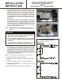
Figure 3
TWO CLIPS TO HOLD PANEL IN PLACE
FILTER ACCESS PANEL
9. Take the two clips and place one on each side of return
panel and using a screw from the unit posts to secure so tab
is over return panel. See Figure 3.
10. Attach filter access panel, above return air opening, flush
with top panel. With panel firmly against flanges, install
screws provided and tighten securely. See Figure 3.
Note: For Units Requiring Limit Replacement.
11. Disconnect all electrical power to unit before replacing limit
control.
12. Remove blower access panel and locate main air limits on
the interior divider panel near the blower outlet duct. See
Figure 4.
WARNING! MARK ALL WIRES AND NOTE TERMINAL
ORIENTATION BEFORE REMOVAL OF WIRING OR
TRANSFER WIRES IMMEDIATELY TO NEW MAIN AIR LIMIT
TO ENSURE PROPER OPERATION OF UNIT.
Figure 4
LOWER LIMIT LOCATION
Figure 5
LIMIT SET TING
155
o
F OPEN ING TEMP
40
o
F DIF FER EN TIAL
(CLOSE @ 155
o
F)
TERMINAL #3
TERMINAL #2
TER MI NAL #1
PART#
UP PER LIMIT LOCATION
INDOOR BLOWER COMPARTMENT

Picture 1
Picture 2
13. The ignition control module is located behind the burner
access panel on all of the R6GP series units. (Compartment is
located to the right of the unit control panel, refer to the Unit
Installation Instructions) Some unit models incorporate a
Fenwal ignition control module. See Picture 1. On these units
the air temperature limits are a single pole, double throw
design and are connected as shown in wiring diagram 1 below.
Also, See Figure 5 to reference the terminal orientation on
these limits.
Most R6GP Series units utilize a UTEC ignition control board;
this configuration can be seen in Picture 2. This control
method utilizes a single pole, single throw air temperature limit.
(Terminals 1 & 3 ONLY – as Shown in Figure 5. Some limits
included in this kit only have terminals 1& 3 and are for use only
on units incorporating the UTEC control.) These units will be
wired as shown in Wiring diagram 2.
Note: Reference the unit wiring diagram located in the unit
control panel or in the unit installation instructions as
needed.
INSTALLATION
INSTRUCTION
INSTALLATION INSTRUCTIONS FOR
HORIZONTAL AIR DISCHARGE KIT
559914
R6GP SERIES 6 & 7 ½ TON EQUIPMENT
Warn ing:
v Improper Air Temperature Limit installation or service
maintenance can cause injury or property damage and
may cause an unsafe condition to exist.
v It is the installers’ responsibility to ensure that the
correct limits are installed in accordance with these
instructions.
v For assistance or additional information consult a
qualified, professional installer or service agency.
a. As determined in steps 1, 2 and 3: remove the correct limit(s)
from the parts kit and it’s individually sealed plastic bag. Label
the wires installed on the limit to be replaced and remove the
appropriate limit from the unit by removing the wires and 2
screws that secure the limit in place. Install the correct limit for
horizontal operation with the same screws and replace the
wiring on the same limit terminals. Repeat if necessary for the
second safety limit replacement.
Note: It is recommended to only replace one limit at a time.
14. Check all terminals for proper connections.
15. Replace blower access panel and reconnect electrical power
to unit.
16. Complete Checklist on back cover of these instructions.
17. Complete the unit installation in accordance with the units
installation instructions.
18. Review the installation details with the building owner.
For units with Utec con trols
For units with Fenwal con trols
Safety Limit Wir ing Di a grams
Wir ing Di a gram #2
Wir ing Di a gram #1

INSTALLATION
INSTRUCTION
INSTALLATION INSTRUCTIONS FOR
HORIZONTAL AIR DISCHARGE KIT
559914
R6GP SERIES 6 & 7 ½ TON EQUIPMENT
NEIHSR07C
APRIL 8, 2009
Hor i zon tal Kit In stal la tion Check list:
Installation Details:
Date of kit installation:
Installation Address:
Building Owner Contact & phone #:
Installer Details:
Installers Name:
Company Information & contact #:
Unit Model number:
- -
Upper Limit Details:
Part # Installed: Temp Setting noted on installed Limit:
Note: For Build to order units, factory configured for horizontal operation annotate "Factory Installation"
For Installations that do not require a change to the safety limit, annotate "No Change Required"
Lower
Limit Details:
Part # Installed: Temp Setting noted on installed Limit:
Note: For Build to order units, factory configured for horizontal operation annotate "Factory Installation"
For Installations that do not require a change to the safety limit, annotate "No Change Required"
Leave these instructions and the unit
Installation instructions with the
Building owner
© Nortek Global HVAC
, LLC 2015. All Rights Reserved.
-
 1
1
-
 2
2
-
 3
3
-
 4
4
-
 5
5
-
 6
6


Unbranded P6SP Installation guide
- Type
- Installation guide
- This manual is also suitable for
Ask a question and I''ll find the answer in the document
Finding information in a document is now easier with AI
Related papers
-
Unbranded R6GP 6, 7.5 - 10 Ton Archived 2/23/12 Installation guide
-
-
-
Reznor R6GP Installation guide
-
-
-
-
Unbranded Horizontal Return Air Panel Kit, 919251 Installation guide
-
-
Other documents
-
Mammoth Natural Gas, High-Altitude Conversion Kit Installation guide
-
-
-
-
-
-
-
-
-