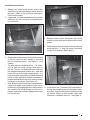
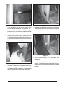
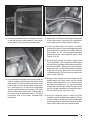
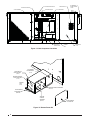
Reznor R6GP is a bottom power entry kit designed for R6GP Series units, allowing passage of high and low voltage wiring connections through the unit bottom pan. This kit enables flexible installation options and supports proper wiring for electrical components such as the unit disconnect and convenience outlet. It ensures safe and efficient power supply to the unit while maintaining compliance with electrical codes and standards.
Reznor R6GP is a bottom power entry kit designed for R6GP Series units, allowing passage of high and low voltage wiring connections through the unit bottom pan. This kit enables flexible installation options and supports proper wiring for electrical components such as the unit disconnect and convenience outlet. It ensures safe and efficient power supply to the unit while maintaining compliance with electrical codes and standards.


-
 1
1
-
 2
2
-
 3
3
-
 4
4
-
 5
5
-
 6
6
-
 7
7
-
 8
8


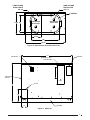
Reznor R6GP is a bottom power entry kit designed for R6GP Series units, allowing passage of high and low voltage wiring connections through the unit bottom pan. This kit enables flexible installation options and supports proper wiring for electrical components such as the unit disconnect and convenience outlet. It ensures safe and efficient power supply to the unit while maintaining compliance with electrical codes and standards.
Ask a question and I''ll find the answer in the document
Finding information in a document is now easier with AI
Related papers
Other documents
-
Unbranded Bottom Power Entry Kit, 920464 Installation guide
-
AG Neovo FMC-02 User manual
-
-
Liebert Ship-Ahead Input/Output Cabinet NXL User manual
-
NAPOLEON WSX040T2AA-N Owner's manual
-
-
SMC Open Path Combustible Gas Detector Quasar 900 Owner's manual
-
Crowcon Open Path Gas Detectors User manual
-
-