Unbranded P8SE Installation guide

Type
Installation guide

This manual is also suitable for

SINGLE PACKAGE CONVERTIBLE AIR CONDITIONER (3-PHASE ONLY)
Premium Model Shown
P8SE SERIES 14 SEER
INSTALLATION INSTRUCTIONS
IMPORTANT
ATTENTION INSTALLERS:
It is your responsibility to know this product better than your customer. This includes being able to install the product
according to strict safety guidelines and instructing the customer on how to operate and maintain the equipment for
the life of the product. Safety should always be the deciding factor when installing this product and using common
sense plays an important role as well. Pay attention to all safety warnings and any other special notes highlighted
in the manual. Improper installation of the furnace or failure to follow safety warnings could result in serious injury,
death, or property damage.
These instructions are primarily intended to assist qualified individuals experienced in the proper installation of this
appliance. Some local codes require licensed installation/service personnel for this type of equipment. Please read all
instructions carefully before starting the installation. Return these instructions to the customer’s package for future
reference.
DO NOT DESTROY. PLEASE READ CAREFULLY & KEEP IN A SAFE PLACE FOR FUTURE REFERENCE.
2
WARRANTY INFORMATION
A warranty certificate with full details is included with the
Air Conditioner. Carefully review these responsibilities with
your dealer or service company. The manufacturer will not
be responsible for any costs found necessary to correct
problems due to improper setup, improper installation,
adjustments, improper operating procedure on the part of
the user, etc. Some specific examples of service calls which
are not included in the limited warranty are:
Correcting wiring problems in the electrical circuit supplying
the Air Conditioner.
Resetting circuit breakers or other switches.
Adjusting or calibrating of thermostat.
USER INFORMATION
INSTALLER INFORMATION
SAFETY INFORMATION ................................................... 4
GENERAL INFORMATION ................................................ 5
Pre - Installation Check ..................................................... 5
Locating the Air Conditioner ............................................. 5
Field Connections for Electrical Power Supply ................. 5
Air Ducts ............................................................................ 5
Unconditioned Spaces .................................................... 5
Acoustical Duct Work ...................................................... 5
AIR CONDITIONER INSTALLATION ................................ 6
Packaging Removal .......................................................... 6
Rigging & Hoisting ............................................................ 6
Minimum Clearance Requirements .................................. 6
Ground Level ..................................................................... 6
Air Filter Requirements ..................................................... 6
Rooftop .............................................................................. 7
Horizontal to Downflow Conversion .................................. 7
Removal of Internal Filter Rack ......................................... 7
Installing Filters in the Filter Rack ..................................... 7
Removing Filters from Filter Rack ..................................... 7
Condensate Drain ............................................................. 7
ELECTRICAL WIRING ....................................................... 8
Pre-Electrical Checklist ..................................................... 8
Line Voltage ...................................................................... 8
Grounding ......................................................................... 8
Unbalanced 3-Phase Supply Voltage ............................... 8
Optional Outdoor Thermostat ........................................... 9
Optional Electric Heater Kits ............................................. 9
AIRFLOW ........................................................................... 10
Blower Speed .................................................................... 10
Fixed Torque ECM Motor .................................................. 11
START UP & SYSTEM CHECK ......................................... 11
Pre-Start Check List .......................................................... 11
Start-Up Procedure ........................................................... 11
Air Circulation ................................................................. 11
System Cooling .............................................................. 11
System Heating .............................................................. 11
AIR CONDITIONER MAINTENANCE ................................ 11
REFRIGERANT CHARGING ............................................. 12
Charging the Unit in AC Mode .......................................... 12
FIGURES & TABLES ......................................................... 13
Figure 8. P8SD Air Conditioner Dimensions ................... 13
Table 6. Center of Gravity & Unit Shipping Weights ........ 13
Electrical Information ........................................................ 14
Figure 9. Wiring Diagram for 208 / 230V Units ............... 14
Figure 10. Wiring Diagram For 460V Units ..................... 15
Figure 11. AC Thermostat Connections (208/230V) ....... 16
Figure 12. AC Thermostat Connections (460V) ............. 16
IMPORTANT SAFETY INFORMATION ............................. 3
ABOUT THE AIR CONDITIONER ...................................... 3
OPERATING INSTRUCTIONS ........................................... 3
Cooling Operation ............................................................. 3
Heating Operation ............................................................. 3
(If optional heat accessory is installed) ............................ 3
Turning the Air Conditioner OFF ....................................... 3
Operating the Indoor Blower Continuously ....................... 3
AIR CONDITIONER MAINTENANCE ................................ 3
Before You Call a Technician: ........................................... 3
3
ABOUT THE AIR CONDITIONER
The P8 Series single packaged convertible air conditioner
is a high efficient self contained cooling unit that will cool
your home year round and provide energy saving comfort.
Additional features and benefits of the P8 air conditioner
include:
• Indoorandoutdoorcoilsaredesignedtooptimizeheat
transfer, minimize size and cost, and increase durability
and reliability.
• EnvironmentallyfriendlyR-410ARefrigerant.
OPERATING INSTRUCTIONS
Cooling Operation
1. Set the thermostat’s system mode to COOL or AUTO and
change the fan mode to AUTO. See Figure 1.
2. Set the temperature selector to the desired temperature
level. The outdoor fan, compressor, and blower motor will
all cycle on and off to maintain the indoor temperature at
the desired cooling level.
Heating Operation
(If optional heat accessory is installed)
1. Set the thermostat’s system mode to HEAT or AUTO and
change the fan mode to AUTO. See
Figure 1.
2. Set the temperature selector to a desired temperature
level. The indoor blower will cycle on and off to maintain
the indoor temperature at the desired heating level.
Turning the Air Conditioner OFF
Change the thermostat’s system mode to OFF and the fan
mode to AUTO. See
Figure 1. NOTE: The system will not
operate, regardless of the temperature selector setting.
Operating the Indoor Blower Continuously
The continuous indoor blower operation is typically used to
circulate the indoor air to equalize a temperature unbalance
due to a sun load, cooking, or fireplace operation.
Set the thermostat fan mode to ON (
Figure 1). The indoor
blower starts immediately, and will run continually until the
fan mode is reset to AUTO.
The continuous indoor blower operation can be obtained with
IMPORTANT SAFETY INFORMATION
Please read all instructions before servicing this equipment.
Pay attention to all safety warnings and any other special
notes highlighted in the manual. Safety markings are used
frequently throughout this manual to designate a degree or
level of seriousness and should not be ignored. WARNING
indicates a potentially hazardous situation that if not avoided,
could result in personal injury or death. CAUTION indicates a
potentially hazardous situation that if not avoided, may result
in minor or moderate injury or property damage.
Figure 1. Digital Thermostat
Fan
Mode
Temperature
Selector
System
Mode
the thermostat system mode set in any position, including
OFF.
AIR CONDITIONER MAINTENANCE
Proper maintenance is most important to achieve the best
performance from the appliance and should be performed
frequently at the beginning of each air conditioning season.
WARNING:
Your Air Conditioner contains liquid and gaseous
refrigerant under pressure. Installation and
servicing should only be attempted by qualified,
trained personnel thoroughly familiar with the
equipment and safe responsible refrigerant
handling procedures. Failure to comply with
this warning could result in equipment damage,
personal injury, or death.
• Keeptheoutdoor unitclean.Hose offperiodicallyand
keep unit fins clear of leaves and grass clippings.
Keep the outdoor unit clear of obstructions.
DO NOT obstruct airflow with tall plants or shrubs. DO
NOT store gasoline or other flammable materials on or
near the outdoor unit.
• Neveroperatetheappliancewithoutalterinstalledin
the return air duct. Inspect filters frequently and replace
when necessary with filter of same dimensional size.
Before You Call a Technician:
• Checkthethermostatsetting.Makesurethesystemmode
and temperature settings are correct.
• Checktheelectricalpanelfortrippedcircuitbreakers.
• Checktheltersfordustaccumulation.
• Checktheoutdoorunitandmakesureitiscleanandnot
covered with grass or leaves.
USER INFORMATION
4
SAFETY INFORMATION
IMPORTANT: Safety markings are used frequently
throughout this manual to designate a degree or level of
seriousness and should not be ignored. WARNING indicates
a potentially hazardous situation that if not avoided, could
result in personal injury or death. CAUTION indicates a
potentially hazardous situation that if not avoided, may result
in minor or moderate injury or property damage.
WARNING:
Improper installation, service, adjustment, or
maintenance may cause explosion, fire, electrical
shock or other hazardous conditions which may
result in personal injury or property damage.
Unless otherwise noted in these instructions,
only factory authorized kits or accessories may
be used with this product.
CAUTION:
This unit uses refrigerant R-410A. DO NOT use
any other refrigerant in this unit. Use of another
refrigerant will damage the unit.
WARNING:
Shut off all electrical power to the unit before
performing any maintenance or service on the
system. Failure to comply may result in personal
injury or death.
WARNING:
These units are fully charged with R-410A
refrigerant and ready for installation. When
a system is installed according to these
instructions, no refrigerant charging is required.
If repairs make it necessary for evacuation and
charging, it should only be attempted by qualified,
trained personnel thoroughly familiar with this
equipment. Some local codes require licensed
installation service personnel to service this
type of equipment. Under no circumstances
should the homeowner attempt to install and/or
service this equipment. Failure to comply with
this warning could result in equipment damage,
personal injury, or death.
INSTALLER INFORMATION
WARNING:
Do not place combustible material on or against
the unit cabinet. Do not place combustible
materials, including gasoline and any other
flammable vapors and liquids, in the vicinity of
the unit.
WARNING:
The safety information listed below must be
followed during the installation, service, and
operation of this unit. Unqualified individuals
should not attempt to interpret these instructions
or install this equipment. Failure to follow safety
recommendations could result in possible
damage to the equipment, serious personal
injury or death.
• The installer must comply with all local codes and
regulations which govern the installation of this type of
equipment. Local codes and regulations take precedence
over any recommendations contained in these instructions.
Consult local building codes and the National Electrical
Code (ANSI CI) for special installation requirements.
• Thisequipmentcontainsliquidandgaseousrefrigerant
under high pressure. Installation or servicing should only
be performed by qualified trained personnel thoroughly
familiar with this type equipment.
• Allelectricalwiringmustbecompletedinaccordancewith
local, state and national codes and regulations and with
the National Electric Code (ANSI/NFPA 70) or in Canada
the Canadian Electric Code Part 1 CSA C.22.1.
• Installationofequipmentmayrequirebrazingoperations.
Installer must comply with safety codes and wear
appropriate safety equipment (safety glasses, work gloves,
fire extinguisher, etc.) when performing brazing operations.
• Installthisunitonlyinalocationandpositionasspeciedon
page 6. This unit is designed only for outdoor installations
and should be located with consideration of minimizing
the length of the supply and return ducts. Consideration
should also be given to the accessibility of fuel, electric
power, service access, noise, and shade.
• Followallprecautionsintheliterature,ontags,andon
labels provided with the equipment. Read and thoroughly
understand the instructions provided with the equipment
prior to performing the installation and operational checkout
of the equipment.
5
Air Ducts
This unit is designed only for use with a supply and return
duct. Air ducts should be installed in accordance with
the standards of the National Fire Protection Association
Standard for Installation of Air Conditioning Systems (NFPA
90A), Standard for Installation of Residence Type Warm Air
Heating and Air Conditioning Systems (NFPA 90B), and all
applicable local codes. NFPA publications are avaialable by
writing to: National Fire Protection Association, Batterymarch
Park, Quincy, ME 02269 or visit www.NFPA.org on the web.
• Designtheductworkaccordingtomethodsdescribedby
the Air Conditioning Contractors of America (ACCA).
• Theductsmustbeproperlysizedandnotexceed.2”W.C.
pressure drop at 400 scfm per nominal ton of cooling
capacity.
• Ductworkshouldbeattacheddirectlytotheunitanges
for horizontal applications.
• Ifroofcurbisinstalled,theductsmustbeattachedtothe
curb hangers, not the unit.
Unconditioned Spaces
All duct work passing through unconditioned space must
be properly insulated to minimize duct losses and prevent
condensation. Use insulation with an outer vapor barrier.
Refer to local codes for insulation material requirements.
Acoustical Duct Work
Certain installations may require the use of acoustical lining
inside the supply duct work.
• Acoustical insulation must be in accordance with the
current revision of the Sheet Metal and Air Conditioning
Contractors National Association (SMACNA) application
standard for duct liners.
• DuctliningmustbeULclassiedbattsorblanketswitha
fire hazard classification of FHC-25/50 or less.
• Fiberduct work may be usedin place of internal duct
liners if the fiber duct work is in accordance with the
current revision of the SMACNA construction standard
on fibrous glass ducts. Fibrous duct work and internal
acoustical lining must be NFPA Class 1 air ducts when
tested per UL Standard 181 for Class 1 ducts.
GENERAL INFORMATION
Packaged Air Conditioner units are ready for easy and
immediate installation on rooftops or ground level slabs. Units
are shipped for horizontal duct connections and can be easily
converted for downflow applications. This air conditioner is
designed only for outdoor installations.
This unit has been designed and tested for capacity and
efficiency in accordance with AHRI Standards. This unit
will provide many years of safe and dependable comfort,
providing it is properly installed and maintained. With regular
maintenance, this unit will operate reliably year after year.
Abuse, improper use, and/or improper maintenance can
shorten the life of the appliance and create unsafe hazards.
Pre - Installation Check
Before you install this unit, the cooling load of the area
to be conditioned must be calculated and a system of
the proper capacity selected. It is recommended that the
area to be conditioned be completely insulated and vapor
sealed.
Check the electrical supply and verify the power supply
is adequate for unit operation. If there is any question
concerning the power supply, contact the local power
company.
All units are securely packed at the time of shipment and
upon arrival should be carefully inspected for damage prior
to installing the equipment at the job site. Verify coil fins
are straight. If necessary, comb fins to remove flattened
or bent fins. Claims for damage (apparent or concealed)
should be filed immediately with the carrier.
Please consult your dealer for maintenance information
and availability of maintenance contracts. Please read
all instructions before installing the unit.
Locating the Air Conditioner
• Survey the job site to determine the best location for
mounting the outdoor unit.
• Chooseanappropriatelocationthatminimizesthelength
of the supply and return air ducts.
• Avoidoverheadobstructions,poorlyventilatedareas,and
areas subject to accumulation of debris.
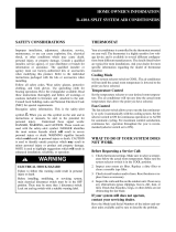
• Sufcientclearanceforunobstructedairowthroughthe
outdoor coil must be maintained in order to achieve rated
performance. See
Figure 2 for minimum clearances to
obstructions.
Field Connections for Electrical Power
Supply
• All wiring must comply with current provisions of the
National Electrical Code (ANSI/NFPA 70) and with
applicable local codes having jurisdiction.
• The minimum size of electrical conductors and circuit
protection must be in compliance with information listed
on the outdoor unit data label.
• Electricalpowersuppliedtotheunitmustbeadequatefor
proper operation of the equipment. The system must be
wired and provided with circuit protection in accordance
with local building codes.
Minimum Required
Clearances to Obstructions
0"
36"
36"
36"
TOP OF UNIT
TO BE
UNOBSTRUCTED
36” For Coil Only
Figure 2. Clearance Requirements
6
Air Filter Requirements
WARNING:
Never operate the unit without a filter in place.
Dust and lint could accumulate on internal parts,
resulting in loss of efficiency, equipment damage
and possible fire. Replace disposable filters with
the same type and size.
• Air lter(s) are not supplied and must be installed in
the unit or in the return air system by the installer. Only
three phase units are equipped with an internal filter rack
assembly.
• IfusinganEconomizerorFreshAirEquipment,thefactory
installed filter rack must be removed prior to installation.
See
page 7 for removal instructions.
• All return air must pass through the lters before
entering the unit.
Recommended filter sizes are listed in
Table 1. NOTE: It is important that all filters be kept clean
and replaced frequently to ensure proper operation of
unit. Dirty or clogged filters will reduce the efficiency of
the unit and result in unit shutdowns.
• Airlterpressuredropmustnotexceed0.08inchesWC.
When replacing the air filters, a suitable air filter must be
installed upstream of the evaporator coil of the return air
system.
• DownowInstallationsrequireaninternallteraccessory
kit to be installed.
• Horizontal Installations require the air lter system be
installed in the return air ductwork.
AIR CONDITIONER INSTALLATION
Packaging Removal
Remove the shipping carton and User’s Manual from the
equipment. Take care not to damage the tubing connections
when removing the carton. For rooftop installations, remove
and discard the two supports attached beneath the unit.
Rigging & Hoisting
WARNING:
To avoid the risk of property damage, personal
injury, or death, it is the rigger’s responsibility
to ensure that whatever means are used to hoist
the unit are safe and adequate:
• Theliftingequipmentmustbeadequateforthe
load. Refer to
Table 6 (page 13) for unit weights.
• Theunitmustbe lifted fromtheholesin the
base rails using cables or chains.
• Spreaderbarsarerequiredtoprotecttheunit
and ensure even loading.
• Keeptheunitinanuprightpositionatalltimes.
The rigging must be located outside the units
center of gravity. Refer to
Figure 8 (page 13)
for locating the center of gravity.
• All panels must be securely in place during
rigging and hoisting.
Minimum Clearance Requirements
P8SD units are certified as cooling equipment for outdoor
installation only.
Figure 2 (page 5) displays the minimum
clearances to obstructions for both Downflow and Horizontal
discharge.
Units may be installed on wood flooring or on Class A, B,
or C roof covering material when used with bottom supply
and return air ducts. If using bottom discharge with return air
ducts, a roof curb must be installed prior to unit installation.
See Rigging and Hoisting section for setting of the unit
(
page 6).
Ground Level
Ground level installations must be located according to local
building codes or ordinances and these requirements:
• Clearancesmustbeinaccordancewiththoseshownin
Figure 2.
• Asuitablemountingpadmustbeprovidedandseparate
from the building foundation. The pad must be level to
ensure proper condensate disposal and strong enough
to support the unit’s weight. The slab height must be a
minimum of 2” (5cm) above grade and with adequate
drainage. See
Figure 3 (page 7).
• Allowsufcientclearancesforaccesstotheinternallter
rack.
Table 1. Internal Filter Size Requirements.
UNIT SIZE INTERNAL FILTER SIZE
P8SE-X36
P8SE-X48
(2)14”x25”
or
(2)14”x25”
P8SE-X60
(2)18”x25”
or
(2)18”x25”
7
Rooftop
Rooftop installations must be located according to local
building codes or ordinances and these requirements:
• Theroofmustbecapableofhandlingtheweightofthe
unit. For unit weights, see
Table 6 (page 13). Reinforce
the roof if necessary.
• Theappropriateaccessoryroofcurb(
Figure 4) must be
installed prior to unit installation. The roof curb must be
square and level to ensure proper condensate drainage.
Please follow all instructions provided with the kit.
• Secure roof curb or frame to roof using acceptable
mechanical methods per local codes. NOTE:
Make sure
the two supports beneath the unit have been removed.
Roof
Curb
Figure 4. Roof Top Installation
2”
Figure 3. Ground Level Installation
Securing
Screws
Figure 5. Internal Filter Rack Location
Horizontal to Downflow Conversion
The unit is shipped ready for horizontal duct connections.
If down flow ducts are required, the unit must be converted
following the steps below for the supply and return ducts.
1. Locate the duct cap inside the duct openings and remove
the screw holding it in place.
2 Lift the cap out of the unit. (Hint: The cap can be pushed
up from the bottom by reaching through the fork slot).
3. Cover the horizontal duct opening with the horizontal duct
cap. The insulation will be on the indoor side.
4. Fasten the cover with screws to seal.
Removal of Internal Filter Rack
1. Remove the return air panel from the unit.
2. Remove the height adjustment screw from the inside of
the rack.
3. Remove (1) screw securing the assembly to the coil located
on the left leg of the rack. NOTE: The assembly can now
be easily collapsed and removed from the unit. See
Figure
5 for filter rack securing screw locations.
Installing Filters in the Filter Rack
1. Remove access panel screws from return air panel. (Hint:
Loosen the unit’s top panel screws near the top edge of
the access panel. The access panel was designed to be
captured underneath the top panel.)
2. Slide the first filter between both guide channels of filter
rack and allow the filter to drop easily into place.
3. Verify the bottom of the filter is within the channels of the
rack.
4. Slide the 2nd filter between both guide channels of filter
rack.
5. Verify the bottom of the filter is within the channels of the
rack.
6. Replace access cover by sliding the top edge of panel
under the lip of the unit’s Top Panel. Secure access panel
by replacing the screws.
Removing Filters from Filter Rack
1. Remove access panel screws from return air panel. (Hint:
Loosen the unit’s top panel screws near the top edge of
the access panel. The access panel was designed to be
captured underneath the top panel.)
2. Remove upper filter by gently pulling filter through the
access panel opening.
3. Remove lower filter by lifting media to top of filter rack.
Remove in the same manner as described in step 2.
4. Install new filter in the filter rack as described in the previous
section.
Condensate Drain
Condensateisremovedfromtheunitthroughthe3/4”female
pipe fitting located on the front side of the unit. Install a 2 inch
condensate trap in the drain line of the same size and prime
with water. When connecting rigid drain line, hold the female
fitting with a wrench to prevent twisting. Do not over tighten!
Refer to local codes and restrictions for proper condensate
disposal requirements. See
Figure 6 (page 8).
8
Condensate
Drain
Figure 6. Condensate Drain Location
• Seetheunitwiringlabelforproperhighandlowvoltage
wiring. Make all electrical connections in accordance with
all applicable codes and ordinances.
• Overcurrentprotectionmustbeprovidedatthebranch
circuit distribution panel and sized as shown on the unit
rating label and according to applicable local codes. See
the unit rating plate for maximum circuit ampacity and
maximum overcurrent protection limits.
• Checkallfactorywiringtothewiringdiagrams.Verifynone
of the connections loosened during shipping or installation.
• Awiringdiagram/schematicislocatedontheinsidecover
of the electrical box of the outdoor unit. The installer should
become familiar with the wiring diagram/schematic before
making any electrical connections to the outdoor unit. See
Figure 9 (page 14) & Figure 10 (page 15).
• Providepowersupplyfortheunitinaccordancewiththe
unit wiring diagram, and the unit rating plate.
CAUTION:
Label all wires prior to disconnection when
servicing controls. Wiring errors can cause
improper and dangerous operation. Verify proper
operation after servicing.
• Units are shipped from the factory wired for 240 volt
transformer operation. For 208V operation, remove the
lead from the transformer terminal marked 240V and
connect it to the terminal marked 208V.
• Internallymountedcircuitbreakersareavailableaseld
installed options. These circuit breakers can be used as
an electrical disconnect.
• Connect the line-voltage leads to the terminals on the
contactor inside the control compartment.
Grounding
WARNING:
The unit cabinet must have an uninterrupted or
unbroken electrical ground to minimize personal
injury if an electrical fault should occur. Do not
use gas piping as an electrical ground!
This unit must be electrically grounded in accordance with
local codes or, in the absence of local codes, with the National
Electrical Code (ANSI/NFPA 70) or the CSA C22.1 Electrical
Code. Use the grounding lug provided in the control box for
grounding the unit.
Unbalanced 3-Phase Supply Voltage
Voltage unbalance occurs when the voltages of all phases
of a 3-phase power supply are no longer equal. This
unbalance reduces motor efficiency and performance. Some
underlying causes of voltage unbalance may include: Lack
of symmetry in transmission lines, large single-phase loads,
and unbalanced or overloaded transformers. A motor should
never be operated when a phase imbalance in supply is
greater than 2%.
Perform the following steps to determine the percentage of
voltage imbalance:
ELECTRICAL WIRING
WARNING:
Shut off all electrical power to the unit before
performing any maintenance or service on the
system. Failure to comply may result in personal
injury or death.
• Electrical connections must be in compliance with
all applicable local codes and ordinances, and with
the current revision of the National Electric Code
(ANSI/NFPA 70).
• For Canadian installations, the electrical connections
and grounding shall comply with the current Canadian
Electrical Code (CSA C22.1 and/or local codes).
Pre-Electrical Checklist
Verify that the voltage, frequency, and phase of the supply
source match the specifications on the unit rating plate.
Verify that the service provided by the utility is sufficient
to handle the additional load imposed by this equipment.
refer to the unit wiring label for proper high and low voltage
wiring.
Verify factory wiring is in accordance with the unit wiring
diagram. See
Figure 9 (page 14) & Figure 10 (page
15). Inspect for loose connections.
Phase balance on 3 phase units must always be checked.
See Unbalanced 3-Phase Supply Voltage section (
page
8).
Line Voltage
• It is recommended that the line voltage to the unit be
supplied from a dedicated branch circuit containing the
correct fuse or circuit breaker for the unit.
• An electrical disconnect must be located within sight
of and readily accessible to the unit. This switch shall
be capable of electrically de-energizing the outdoor unit.
See unit data label for proper incoming field wiring. Any
other wiring methods must be acceptable to authority
having jurisdiction.
• Useonlycopperwireforthelinevoltagepowersupplyto
this unit (
Table 2 (page 9)). Use proper code agency
listed conduit and a conduit connector for connecting
the supply wires to the unit. Use of rain tight conduit is
recommended.
9
Optional Outdoor Thermostat
An outdoor thermostat can be installed in the field with 2-stage
electric heat. To install the outdoor thermostat, remove the
orange wire from the E terminal on the terminal block, and
connect to the outdoor thermostat. Connect the other side
of the outdoor thermostat to W2 from the thermostat.
Optional Electric Heater Kits
This packaged air conditioner is designed to allow optional
electric heat to be field installed as required by the building’s
particular heating load. The options available for each unit
are shown in the heater kit installation instructions.
Optional field-installed electric heater kits are available
in 5 kw to 20 kw heating capacities for single phase, and
9 kw to 15 kw heating capacities for three phase. A separate
installation instruction document for the electric heaters and
their application is shipped with the heater kits.
A single stage 24VAC thermostat should be used with
these units. If electric heat is installed, a single-stage or
two- stage heating thermostat will be required depending
on the heater kit. Install the heater kits as directed by the
instructions supplied with the heater kit. Follow all cautions
and warnings as directed.
1. Measure the line voltages
of your 3-phase power
supply where it enters the
building and at a location
that will only be dedicated
to the unit installation. (at
the units circuit protection
or disconnect).
EXAMPLE:
AB = 451V
BC = 460V
AC = 453V
2. Determine the average voltage in the power supply.
In this example, the measured line voltages were 451, 460,
and 453. The average would be 454 volts (451 + 460 +
453 = 1,364 / 3 = 454).
3. Determine the maximum deviation:
EXAMPLE
From the values given in step 1, the BC voltage (460V) is
the greatest difference in value from the average:
460 - 454 = 6
454 - 451 = 3
454 - 453 = 1
4. Determine percent of
voltage imbalance by using
the results from steps 2 & 3
in the following equation.
6
454
100 x
= 1.32%
EXAMPLE
maxvoltage deviation
fromaverage voltage
=100 x
averagevoltage
% Voltage Imbalance
The amount of phase imbalance (1.32%) is satisfactory
since the amount is lower than the maximum allowable 2%.
Please contact your local electric utility company if your
voltage imbalance is more than 2%.
Thermostat Connections
Several thermostat options are available depending on the
accessories installed with the unit. See
Figure 11 (page
16) for 208/230V units or Figure 12 (page 16) for 460V
units. Select a thermostat that operates in conjunction with
the installed accessories. The low voltage wires must be
properly connected to the units low voltage terminal block.
Recommended wire gauge and wire lengths for typical
thermostat connections are listed in
Table 3.
IMPORTANT NOTE:
The thermostat should be mounted about 5 feet above the
floor on an inside wall. DO NOT install the thermostat on
an outside wall or any other location where its operation
may be adversely affected by radiant heat from fireplaces,
sunlight, or lighting fixtures, and convective heat from
warm air registers or electrical appliances. Refer to the
thermostat manufacturer’s instruction sheet for detailed
mounting and installation information.
Table 2. Copper Wire Size
COPPER WIRE SIZE — AWG
(1% VOLTAGE DROP)
SUPPLY WIRE LENGTH-FEET
SUPPLY
CIRCUIT
AMPACITY
200 150 100 50
6 8 10 14 15
4 6 8 12 20
4 6 8 10 25
4 4 6 10 30
3 4 6 8 35
3 4 6 8 40
2 3 4 6 45
2 3 4 6 50
2 3 4 6 55
1 2 3 4 60
Wire Size based on N.E.C. for 60° type copper conductors.
Table 3. Thermostat Wire Gauge
THERMOSTAT
WIRE GAUGE
MAXIMUM RECOMMENDED
THERMOSTAT WIRE LENGTH (FT)
24 25
22 45
20 70
18 110
10
AIRFLOW
All heater kit temperature rise data in Table 4 was calculated
using 10kW heaters (9kW for 3 phase units). For other sized
heater kits, use the following steps below to determine the
heat rise for your particular heater kit.
1. Determine your CFM. NOTE: Find this data by locating
your blower motor tap settings in the data supplied with
the Installation Instructions.
2. Locate your heater kits kW value and Btu/h in
Table 5
(page 11).
3. Input the values into the following equation:
Temp Rise: ΔT= (Btu/h)/(CFM*1.08)
NOTE: Generally the heat rise should be 30 - 40 degrees.
Anything above 40 degrees should be avoided.
Blower Speed
CAUTION:
To avoid personal injury or property damage,
make certain that the motor leads cannot
come into contact with any uninsulated metal
components of the unit.
The blower speed is preset at the factory for operation at
the same speed for heating and cooling. Factory settings
are listed in
Table 4. For optimum system performance and
comfort, it may be necessary to change the factory set speed.
208 / 230V
MODEL #
P8SD -
FT
OZ
EXTERNAL STATIC PRESSURE DROP - INCHES WATER COLUMN
0.1 0.2 0.3 0.4 0.5 0.6 0.7 0.8
X36C
Tap 1** 19 1126 25 1065 27 1024 28 940 30 853 33 768 37 702 41 637 45
Tap 2* 25 1315 22 1268 22 1206 24 1144 25 1076 26 987 29 907 31 839 34
Tap 3 32 1492 19 1438 20 1386 21 1337 21 1287 22 1230 23 1171 24 1062 27
Tap 4 36 1587 18 1534 19 1494 19 1439 20 1388 20 1338 21 1280 22 1216 23
Tap 5 40 1684 17 1638 17 1591 18 1541 18 1492 19 1444 20 1390 20 1336 21
X48C
Tap 1** 20 1238 23 1170 24 1108 26 1051 27 986 29 890 32 817 35 755 38
Tap 2 25 1403 20 1351 21 1301 22 1232 23 1175 24 1125 25 997 29 955 30
Tap 3* 38 1772 16 1727 16 1670 17 1621 18 1568 18 1509 19 1463 19 1399 20
Tap 4 46 1968 14 1926 15 1873 15 1823 16 1774 16 1717 17 1665 17 1619 18
Tap 5 60 2242 13 2183 13 2143 13 2098 14 2044 14 1995 14 1953 15 1907 15
X60
Tap 1** 21 1161 24 1116 25 1084 26 1031 28 954 30 895 32 834 34 779 37
Tap 2 31 1553 18 1521 19 1474 19 1437 20 1379 21 1335 21 1276 22 1183 24
Tap 3* 40 1862 15 1818 16 1766 16 1731 16 1678 17 1635 17 1599 18 1539 18
Tap 4 46 2009 14 1973 14 1923 15 1887 15 1838 15 1796 16 1752 16 1703 17
Tap 5 60 2288 12 2246 13 2210 13 2170 13 2132 13 2094 14 2050 14 2014 14
406V
MODEL #
P8SD -
EXTERNAL STATIC PRESSURE DROP - INCHES WATER COLUMN
0.1 0.2 0.3 0.4 0.5 0.6 0.7 0.8
X36D
Tap 1** 1124 25 1040 27 981 29 908 31 824 35 750 38 687 41 623 46
Tap 2* 1320 22 1266 22 1210 23 1159 25 1100 26 1029 28 945 30 884 32
Tap 3 1542 18 1479 19 1443 20 1386 21 1329 21 1283 22 1234 23 1182 24
Tap 4 1642 17 1594 18 1533 19 1492 19 1441 20 1396 20 1340 21 1300 22
Tap 5 1750 16 1694 17 1642 17 1600 18 1560 18 1510 19 1467 19 1421 20
X48D
Tap 1** 1279 22 1214 23 1134 25 1078 26 1034 27 944 30 855
33 800 36
Tap 2 1510 19 1452 20 1399 20 1338 21 1294 22 1236 23 1174 24 1059 27
Tap 3* 1760 16 1711 17 1641 17 1597 18 1545 18 1488 19 1435 20 1386 21
Tap 4 1949 15 1912 15 1858 15 1789 16 1748 16 1701 17 1646 17 1603 18
Tap 5 2242 13 2153 13 2110 13 2063 14 2016 14 1965 14 1922 15 1870 15
X60D
Tap 1** 1228 23 1150 25 1074 26 1014 28 956 30 867 33 769 37 705 40
Tap 2 1670 17 1617 18 1551 18 1497 19 1458 20 1417 20 1342 21 1303 22
Tap 3* 1926 15 1891 15 1850 15 1783 16 1741 16 1680 17 1634 17 1579 18
Tap 4 2087 14 2029 14 1981 14 1939 15 1885 15 1834 16 1780 16 1721 17
Tap 5 2278 12 2233 13 2193 13 2141 13 2098 14 2046 14 2001 14 1943 15
NOTES:
Airflow performance is with a dry coil
* Denotes factory set cooling speed
** Denotes factory set electric heating speed
Calculations made based on 9KW/H
Table 4. P8 Series Packaged Air Conditioner Blower Curves
11
Fixed Torque ECM Motor
1. Shut off all electrical power to the unit and remove the
blower panel. Locate the orange and red wires terminated to
the blower motor. NOTE: The orange wire controls cooling
operation while the red wire controls heating operation.
2. Verify the required speed from the airflow data found in
Table 4. Place appropriate wire on the correct motor speed
tap for the required airflow point.
START UP & SYSTEM CHECK
Pre-Start Check List
Verify the unit is level and allows condensate to drain.
Verify the outdoor coil and top of the unit are free from
obstructions and debris, and all equipment access/control
panels are in place.
Verify that the duct work is sealed to prevent air leakage.
Verify that the line voltage power leads are securely
connected and the unit is properly grounded.
Verify that the low voltage wires are securely connected
to the correct leads on the low voltage terminal strip.
Verify that the outdoor fan turns freely.
Verify that the power supply branch circuit overcurrent
protection is sized properly.
Verify that the thermostat is wired correctly. The thermostat
system mode should be set to OFF and the thermostat
fan mode should be set to AUTO.
Start-Up Procedure
Close all electrical disconnects to energize the system.
Air Circulation
Leave the thermostat system mode on OFF, and set the fan
mode to ON. Blower should run continuously. Check the air
delivery at the supply registers and adjust register openings
for balanced air distribution. Examine ductwork for leaks or
obstruction if insufficient air is detected. Set the thermostat
fan mode to AUTO. The blower should stop running.
WARNING:
If the unit is equipped with a crankcase heater,
allow 24 hours prior to continuing the start up
procedures to allow for heating of the refrigerant
compressor crankcase. Failure to comply may
result in damage and could cause premature
failure of the system. This warning should be
followed at initial start up and any time the power
has been removed for 12 hours or longer.
System Cooling
1. Set the thermostat’s system mode to COOL and the fan
mode to AUTO. Gradually lower the thermostats setpoint
below room temperature and verify the outdoor unit and
indoor blower energize.
2. Feel the air being circulated by the indoor blower and verify
that it is cooler than ambient temperature. Listen for any
unusual noises. If unusual sounds occur, determine the
source of the noise and correct as necessary.
3. Allow the cooling system to operate for several minutes
and then set the temperature selector above room
temperature. Verify the fan and compressor cycle off
with the thermostat. NOTE: The blower should also stop
unless fan mode is set to ON.
System Heating
If the unit has been equipped with optional electric heater
kits, set the thermostat's system mode to HEAT and the fan
mode to AUTO. Verify the compressor and outdoor fan are
not energized but that the blower and heaters are. Feel the
air being circulated by the indoor blower and verify that it is
warmer than ambient temperature. Listen for any unusual
noises. If unusual sounds occur, determine the source of
the noise and correct as necessary.
AIR CONDITIONER MAINTENANCE
WARNING:
To prevent electrical shock, personal injury, or
death, disconnect all electrical power to the unit
before performing any maintenance or service.
The unit may have more than one electrical
supply.
Proper maintenance is important to achieve optimum
performance from the Air Conditioner. The ability to properly
perform maintenance on this equipment requires certain
mechanical skills and tools. If you do not possess these
skills, contact your dealer for maintenance. Consult your
local dealer about the availability of maintenance contracts.
Routine maintenance should include the following:
• Inspect the condensate drain and outdoor coil at the
beginning of each cooling season. Remove any debris.
Clean the outdoor coil and louvers as necessary using a
mild detergent and water. Rinse thoroughly with water.
• Inspect the electrical connections for tightness at the
beginning of each heating and cooling season. Service
as necessary.
• Inspectandcleanorreplaceairltersatthebeginning
of each heating and cooling season, or more frequently
if required.
CAUTION:
The unit should never be operated without a
filter in the return air system. Replace disposable
filters with the same type and size.
• Themotorsforthecirculatingairblowerandtheoutdoor
fan are pre-lubricated at the factory. No further oiling is
required for the life of this product.
KW/H BTU/H
5 17,060
8 27,297
9 30,709
10 34,121
15 51,182
20 68,242
Table 5. kW & Btu/h Ratings
12
REFRIGERANT CHARGING
WARNING:
Single Packaged Air Conditioners are shipped
fully charged with R-410A refrigerant and ready
for installation. When a system is installed
according to these instructions, no refrigerant
charging is required. If repairs make it necessary
for evacuation and charging, it should only be
done by qualified, trained personnel thoroughly
familiar with this equipment. Some local codes
require licensed installation/service personnel
to service this type of equipment. Under no
circumstances should the owner attempt to
install and/or service this equipment. Failure to
comply with this warning could result in property
damage, personal injury, or death.
The system refrigerant charge can be checked and adjusted
through the service ports provided at the front panel. Use
only gauge lines which have a Schrader depression device
present to actuate the valve.
NOTES:
• Toachieveratedcapacityandefciencythecompressor
must be exposed to refrigerant for at least 24 hours prior
to running and then must be run for a minimum of 12
hours.
• Therefrigerantchargingchart(
Figure 7) is applicable to
listed assemblies of equipment and at listed airflows for
the indoor coil. Assemblies of indoor coils and outdoor
units not listed are not recommended.
Charging the Unit in AC Mode
(Outdoor Temperatures Above 65F.)
1. With the system operating at steady-state, measure the
liquid refrigerant pressure in psig at the service valve.
2. Measure the liquid refrigerant temperature in Fahrenheit
at the service valve.
3. For the temperature measured, determine the required
liquid refrigerant pressure from the charging chart (
Figure
7).
4. If the pressure measured in step 1 is greater than the
required liquid refrigerant pressure determined in step
4, then there is too much charge in the system. Remove
refrigerant and repeat steps 1 through 3 until the system
is correctly charged.
5. If the pressure measured in step 1 is less than the required
liquid refrigerant pressure determined in step 4, then there
is too little charge in the system. Add refrigerant and repeat
steps 1 - 3 until the system is correctly charged.
90 95 100 105 110 115 120 125130
Liquid Temperature (F)
Liquid Pressure (psig)
P8SE CHARGING CHART - COOLING
75
80
85
200
220
240
260
280
300
320
340
360
380
400
420
440
460
480
500
520
540
560
580
600
135
3 TON MODELS
5 TON MODELS
4 TON MODELS
Add refrigerant if below curve
Remove refrigerant if above curve
Figure 7. Charging Chart for 3, 4, & 5 Ton Units
13
Back View
131/2
16
13 7/10
13 1/2
16
12 9/20
11 3/4
22 3/4
55 4/5
C
HORIZONTAL
SUPPLY DUCT
OPENING HORIZONTAL
RETURN DUCT
OPENING
4
CONDENSING
COIL
5
8
4
Side View
1 1/4 Ø Power Entry
1 3/4 Ø Power Entry (Capped)
22/25 Ø Control Wiring Entry
23 3/5
27 1/5
30
1 4/5
4
Figure 8. P8SD Air Conditioner Dimensions
FIGURES & TABLES
Table 6. Center of Gravity & Unit Shipping Weights
MODEL
NUMBER
P8SE -
UNIT
SHIPPING
WEIGHT
CENTER OF GRAVITY
HEIGHT -C-
(IN INCHES)
-A- -B-
WITH BASE RAILS WITHOUT BASE RAILS
X36 375 29 20.5 35.0 30.76
X48 398 29 20.5 35.0 30.76
X60 437 27.25 23.5 43.0 39.3
NOTE: To determine unit weight, subtract 21lbs from unit shipping weight.
Top View
24.9
13.5
16
12
13.3
13.5
16
12
CG
A
47.5
.75" NPT Female
Drain Connector
B
DOWNFLOW
SUPPLY DUCT
OPENING
DOWNFLOW
RETURN DUCT
OPENING
23.5
14
Figure 9. Wiring Diagram for 208 / 230V Units
WIRING DIAGRAM
NOTES:
FIELD WIRING
LEGEND:
LOW VOLTAGE
HIGH VOLTAGE
208/230 VoltConvertable Packaged Air Conditioner Three Phase 60Hz
1. Disconnect all power before servicing.
2. For supply connections use copper conductors only.
3. Not suitable on systems that exceed 150 V to ground.
4. If any of the original wire as supplied with the furnace must be
replaced, it must be replaced with wiring material having a
temprature rating of at least 105°C.
1. Couper le courant avant de faire letretien.
2. Employez uniquement des conducteurs en cuivre.
3. Ne convient pas aux installations de plus de
150 V la terre.
5. For supply wire ampacities and overcurrent protection, see unit
rating plate.
711011A
(Replaces 7110110)
11//14
1
2
3
4
5
6
7
8
9
R
C
S
1
5
2
6
3
4
TO 208/230 VAC
POWER SUPPLY
9
8
1
7
6
5
4
3
2
9
8
1
7
6
5
4
3
2
9
8
1
7
6
5
4
3
2
9
8
1
7
6
5
4
3
2
COMPRESSOR
COMPRESSOR
CONTACTOR
CAPACITOR
PLUG
A
OUTDOOR
FAN MOTOR
PRESSURE
SWITCH
TO DISCHARGE
AIR SENSOR
3 AMP
FUSE
T2
T1
N
G
L
C
T3
T4
T5
BLOWER
MOTOR
TRANSFORMER
T3
T2
T1
CCH
L1L2L3
T1T2T3
24V
240V
208V
COM
GC
W1 A1Y2Y1 R
ORANGE
BLACK
BLACK
BLACK
YELLOW
BLACK
BLUE
YELLOW
RED
RED
RED
RED
ORANGE
BLUE
BLUE
YELLOW
YELLOW
YELLOW
YELLOW
ORANGE
BLACK
BLACK
GREY
GREY
GREEN
BLACK
ORANGE
GREEN
GREEN
GREEN
GREEN/GREY
RED
RED
RED
RED
RED
BROWN
RED
BLACK
BLUE
WHITE
BLACK
WHITE
YELLOW
YELLOW
BK
BK
BK
WHITEWHITE
Electrical Information
15
1
2
3
4
5
6
7
8
9
10
11
12
1
2
3
4
5
6
7
8
9
10
11
12
R
C
S
1
5
2
C
3
4
TO 460 VAC
POWER SUPPLY
9
8
1
7
6
5
4
3
2
9
8
1
7
6
5
4
3
2
9
8
1
7
6
5
4
3
2
9
8
1
7
6
5
4
3
2
COMPRESSOR
COMPRESSOR
CONTACTOR
CAPACITOR
OUTDOOR
FAN MOTOR
PRESSURE
SWITCH (46)
TO DISCHARGE
AIR SENSOR
T2
T1
N
G
L
C
T3
T4
T5
BLOWER
MOTOR
TRANSFORMER
T3
T2
T1
CCH
L1L2L3
T1T2T3
W1A1CG R Y2 Y1
3 AMP
FUSE
24V
480V
COM
PRESSURE
SWITCH
LOW
PRESSURE
SWITCH
RED
RED
ECONOMISER
PLUG
HEATER
PLUG
RED
RED
ORANGE
BLUE
BLUE
BLUE
YELLOW
YELLOW
YELLOW
YELLOW
ORANGE
BLACK
BLACK
GREY
GREY
GREEN
BLACK
GREEN
GREY
GREY
GREEN
GREEN
RED
RED
RED
BROWN
ORANGE
RED
BLACK
BLUE
WHITE
BLACK
BLACK
BLACK
YELLOW
BLACK
BLUE
BLACK
WHITE
RED
YELLOW
YELLOW
BK
BK
BK
WHITE
WHITE
WHITE
WHITE
WIRING DIAGRAM
NOTES:
FIELD WIRING
LEGEND:
LOW VOLTAGE
HIGH VOLTAGE
460 VoltConvertable Packaged Air Conditioner Three Phase 60Hz
1. Disconnect all power before servicing.
2. For supply connections use copper conductors only.
3. If any of the original wire as supplied with the furnace must be
replaced, it must be replaced with wiring material having a
temprature rating of at least 105°C.
1. Couper le courant avant de faire letretien.
2. Employez uniquement des conducteurs en cuivre.
4. For supply wire ampacities and overcurrent protection, see unit
rating plate.
WIRING DIAGRAM
710863A
(Replaces 7108630)
11//14
Figure 10. Wiring Diagram For 460V Units
10071070 (NEW)
Specifications & illustrations subject to change without notice or incurring obligations (07/15).
O’Fallon, MO, © Nortek Global HVAC LLC 2015. All Rights Reserved.
R
Y
C
G
W
1
2
3
4
5
6
7
8
9
Gray
Yellow
Blue
ECONOMIZER PLUG
INDOOR
THERMOSTAT
SUB-BASE
1
2
3
4
5
6
7
8
9
Brown
Orange
ACCESSORY
HEAT PLUG
C
W1
R
Y2
Y1
G
TERMINAL
STRIP
Red
Black
Green
FROM TRANSFORMER
FROM CONTACTOR - Optional
(Check T-stat Instructions)
Figure 11. AC Thermostat Connections (208/230V)
Figure 12. AC Thermostat Connections (460V)
  • Page 1 1
  • Page 2 2
  • Page 3 3
  • Page 4 4
  • Page 5 5
  • Page 6 6
  • Page 7 7
  • Page 8 8
  • Page 9 9
  • Page 10 10
  • Page 11 11
  • Page 12 12
  • Page 13 13
  • Page 14 14
  • Page 15 15
  • Page 16 16

Unbranded P8SE Installation guide

Type
Installation guide
This manual is also suitable for

Ask a question and I''ll find the answer in the document

Finding information in a document is now easier with AI