Page is loading ...

Installation and maintenance manual for
mineral insulated cable systems applied
to pipes and vessels
Industrial Heat
Tracing

ii | nVent.com
Important Safeguards and Warnings
WARNING: FIRE AND SHOCK HAZARD.
nVent RAYCHEM heat-tracing systems must be
installed correctly to ensure proper operation and to
prevent shock and fire. Read these important warnings
and carefully follow all the installation instructions.
• To minimize the danger of fire from sustained
electrical arcing if the heating cable is damaged
or improperly installed, and to comply with nVent
requirements, agency certifications, and national
electrical codes, ground-fault equipment protection
must be used on each heating cable branch circuit.
Arcing may not be stopped by conventional circuit
breakers.
• Approvals and performance of the heat-tracing
systems are based on the use of approved
components and accessories.
• Cable terminations must be kept dry before, during,
and after installation.
• Damaged heating cable can cause electrical arcing or
fire. Use only RAYCHEM approved pipe straps or tie
wire to secure the cable to the pipe.
• Damaged heating cable or terminations must be
repaired or replaced. Contact factory for assistance.
• Use only fire resistant insulation which is compatible
with the application and the maximum exposure
temperature of the system to be traced.
• To prevent fire or explosion in hazardous locations,
verify that the maximum sheath temperature of the
heating cable is below the autoignition temperature of
the gases in the area. For further information, see the
design documentation.
• Heating cables are capable of reaching high
temperatures during operation and can cause burns
when touched. Avoid contact when cables are
powered. Insulate the pipe before energizing the
cable. Use only properly trained personnel.
• Material Safety Data Sheets (MSDSs) are available on
our website: nVent.com

nVent.com
|
iii
Table of Contents
1
General Information 1
1.1 Use of the Manual 1
1.2 Safety Guidelines 2
1.3 Typical System 2
1.4 Electrical Codes 3
1.5 Warranty and Approvals 3
1.6 Heating Cable Construction 4
1.7 Heating Cable Identification 6
1.8 Heating Cable Temperature Information 7
1.9 General Installation Guidelines 7
1.10 Heating Cable Storage 9
2
Pre-Installation Checks 10
2.1 Check Materials Received 10
2.2 Check Piping to be Traced 10
2.3 Check Tools 10
3
Heating Cable Installation 11
3.1 Heating Cable Handling 11
3.2 Heating Cable Installation on Pipes 16
3.3 Temperature Sensor Installation for Pipes 23
3.4 Heating Cable Installation on Tanks and Vessels 24
3.5 Temperature Sensor Installation for Vessels 27
4
Component Installation 28
4.1 General Component Information 28
5
Control and Monitoring 30

iv | nVent.com
6
Thermal Insulation and Marking 31
6.1 Pre-Insulation Checks 31
6.2 Insulation Installation Hints 31
6.3 Marking 32
6.4 Post-Insulation Testing 32
7
Power Supply and Electrical Protection 33
7.1 Voltage Rating 33
7.2 Electrical Loading 33
7.3 Temperature Controller Wiring 34
8
Commissioning and Preventive Maintenance 35
8.1 Tests 35
8.2 Preventive Maintenance 37
9
Test Procedures 39
9.1 Visual Inspection 39
9.2 Insulation Resistance Test – Test 1 39
9.3 Continuity (Resistance) Test – Test 2 40
9.4 Insulation Resistance and Continuity Test 41
10
Troubleshooting Guide 44
11
Installation and Inspection Records 48
Heating Cable Installation Record 48
Installation Record Required for Class I, Division
1,Hazardous Locations According to IEEE 515 50
Heating Cable Commissioning Record 52
Maintenance Log Record 54

1
nVent.com
|
1
General Information
1.1 Use of the Manual
This installation and maintenance manual is for
RAYCHEM Mineral Insulated (MI) heat-tracing
systems installed on thermally insulated metal pipes
and vessels only. This includes RAYCHEM XMI-A Alloy
825 sheathed, XMI-L low temperature sheath and
copper sheathed pre-terminated,
series-resistance MI heating cables and components.
This manual assumes that the heating cable designs
have been completed using TraceCalc Pro software
available from nVent or following the design steps in
H56884, Mineral Insulated Heating Cables, found in the
Industrial Heat-Tracing Product Selection and Design
Guide. nVent offers complete integrated service from
original design, to product specification, to installation
of the complete system. We also provide future
maintenance of the installation, if required.
For design assistance, technical support, or
information regarding applications where the
MI heating cable will be used for heat-tracing of
plastic pipes, flexible or expansion joints, or in
submerged environments, please contact your nVent
representative or nVent directly.
nVent
7433 Harwin Drive
Houston, TX 77036
USA
Tel: +1.800.545.6258
Fax: +1.800.527.5703
nVent.com
Important: For the nVent warranty and agency
approvals to apply, the instructions that are
included in this manual and with associated
products must be followed.

1
General Information
2 | nVent.com
1.2 Safety Guidelines
The safety and reliability of any heat-tracing
system depends on the quality of the products
selected, and on proper design, installation, and
maintenance. Incorrect design, handling, installation,
or maintenance of any of the system components
can cause underheating or overheating of the pipe,
or damage to the heating cable system, and may
result in system failure, electric shock, or fire. The
guidelines and instructions contained in this guide
are important. Follow them carefully to minimize
these risks and to ensure that the MI system
performs reliably.
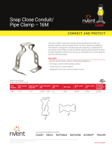
1.3 Typical System
Electric Heat Trace warning label
Pipe to be
heated
Stainless steel
pipe straps, banding,
or tie wire
Tie wire
Heating cable
Pipe insulation
Drip loop
(coil excess cold lead)
Cold
lead
Junction box
Circuit
ID tag
To
power
supply
Hot-cold joint
Figure 1: Typical Design B system

1
General Information
nVent.com
|
3
1.4 Electrical Codes
Articles 427 and 500 of the National Electrical Code
and Sections 18 and 62 of the Canadian Electrical
Code, Part 1, in particular, govern the installation of
electrical heat-tracing systems in hazardous and
nonhazardous locations. Installation of heat-tracing
systems must comply with all national and local
codes. In particular, ground-fault equipment protection
is required for all electric heat-tracing installations to
prevent arcing, fire, and shock if the cable is improperly
installed or damaged.
1.5 Warranty and Approvals
Raychem XMI-A Alloy 825 sheath and copper
sheath MI heating cables are approved for use in
nonhazardous locations and Class I, Division 1 & 2
Groups A, B, C, D, Class II, Division 1 & 2, Groups E, F,
G, Class III hazardous locations. Class I Zone 1 AEx eb
IIC T* Gb – for US and Ex 60079-30-1 IIC T* Gb – for
Canada.
Raychem XMI-L low temperature sheath heating cables
are approved for use in Class I, Division 2 Groups
A, B, C, D, Class II, Division 2, Groups E, F, G Class III
hazardous locations and Class I Zone 2 AEx nA IIC T*
Gc – for US and Ex 60079-30-1 IIC T* Gc – for Canada.
Refer to specific product data sheets for details.
Note: T*- refer to design documentation
nVent’s limited standard warranty applies to all
products. You can access the complete warranty
on nVent.com. To qualify for an extended 10-year
warranty, register online within 30 days of
installation at nVent.com

1
General Information
4 | nVent.com
1.6 Heating Cable Construction
The heating cables are available as factory-terminated
units in the configurations shown in Table 1.
TABLE 1: MI HEATING CABLE CONFIGURATION
MI cable
design
Number of
conductors Configuration
XMI-A Heating Cables
A Single conductor
(XMI-A61 series)
Heated length Cold lead length
B Single conductor
(XMI-A61 series)
Heated
length
Cold lead
length
Cold lead
length
D Dual conductor
(XMI-A32 and
XMI-A62 series)
Heated length
Cold lead length
E Dual conductor
(XMI-A32 and
XMI-A62 series)
Heated
length
Cold lead
length
Cold lead
length
XMI-L Heating Cables
D
Dual conductor
(XMI-L32 and
XMI-L62 series)
Heated length
Cold lead length
E
Dual conductor
(XMI-L32 and
XMI-L62 series)
Heated
length
Cold lead
length
Cold lead
length

1
General Information
nVent.com
|
5
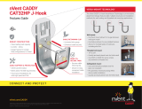
A sectional view of a Design D XMI-A Alloy 825
sheath MI heating cable is shown in Figure 2. All
of the cables include both a heating section and
a non-heating cold lead section. These sections
are joined in the hot-cold joint where the heating
element is spliced into larger bus wires. A final
transition at the end of the cold lead section
provides an environmental seal and tails for the
electrical connection. At the opposite end of the
cable, the conductors of Design D cables are joined
and hermetically sealed within an end cap. XMI-L
low temperature sheath cables have an additional
corrugated sheath over the heated section as
shown in Figures 3 and 4.
Pot
Tails
(standard length
12 in (30 cm)
Bus wires Gland
connector
Hot-cold
joint
Cold leadHeated length
(length as ordered)
End
cap
Heating
element
Figure 2: Sectional view of Design D XMI-A MI cable
Heating
cable
Hot-cold joint
Gland
connector
End cap
Corrugated sheath
Pot
Conduit plug
Heated length
(length as ordered)
Cold lead
Figure 3: Sectional view of Design D XMI-L MI cable
Hot-cold
joint
Heating
cable
Hot-cold jointGland
connector
Corrugated sheath
Cold lead Cold lead
Heated length
(length as ordered)
Pot
Figure 4: Sectional view of Design E XMI-L MI cable

1
General Information
6 | nVent.com
1.7 Heating Cable Identification
Each MI heating cable is supplied with an
identification tag on which the heating cable catalog
number is permanently printed. In addition to its
identification purposes, the catalog number provides
information regarding the heating cable length,
power output, and operating voltage. Also printed
on the tag are the designer’s circuit identification
number, serial number and the maximum
temperature the cable sheath may attain along with
other design information.
If the cable has been designed for a hazardous
location, the area classification is printed in the ‘Haz.
Locations’ section of the tag.
Figure 5: Typical MI identification tag (front)
The heating cable catalog number may be broken
out as follows:
Gland size (NPT)
Hot/cold joint type
X - use for XMI-A Alloy 825 sheath
C - use for XMI-L low temperature sheath
Y - use for copper sheath
Cold lead code
Cold lead length (in feet)
Metric: 2.1M = 2.1 meters
Heating cable voltage
Heating cable wattage
Heating cable length (in feet)
Metric: 10.7M = 10.7 meters
Heating cable reference
Heating cable design
configuration (A, B, D, E)
D/32SA2200/35/200/120/7/LS23A/X/N12
Figure 6: MI heating cable catalog number

1
General Information
nVent.com
|
7
WARNING: Fire or explosion hazard. Ensure that
the information provided in the Haz. Locations and
Temp. Code [Max. Sheath Temp.] fields comply with
the area in which the heating cable will be installed.
1.8 Heating Cable Temperature Information
MI heating cables are available for a variety of
applications, with several sheath materials to suit
different temperature requirements. The maximum
maintain and exposure temperatures for these sheath
materials is shown in Table 2.
TABLE 2:
MAXIMUM CABLE TEMPERATURE
Product family
Maximum
maintain
temperature
Maximum
continuous
exposure
temperature
Maximum continuous
exposure temperature for
hot/cold joints and end cap
XMI-A 1022°F (550°C) 1200°F (650°C) 1022°F (550°C)
XMI-L (Note 1) 752°F (400°C) 1022°F (550°C) 1022°F (550°C)
Copper 300°F (150°C) 392°F (200°C) 300°F (150°C)
LSZH jacketed
copper
158°F (70°C) 194°F (90°C) 194°F (90°C)
Note 1: 842°F/450°C if corrosives are present
1.9 General Installation Guidelines
These guidelines are provided to assist the installer
throughout the installation process and should be
reviewed before the installation begins.
Avoid damage to the MI heating cable as follows:
• Do not repeatedly bend and straighten the cable.
• Do not bend within 6 inches (15 cm) of a splice,
the hot-cold joint, or the end cap.
• Do not bend the cold lead within 6 in (15 cm) of
the termination pot seal.
• Do not alter cable length.
• Do not energize before installation is complete.
• Do not use screw type adjustable pipe straps/
banding.
• Avoid crushing and excessive bending or pulling
of cold leads during installation, testing and
commissioning

1
General Information
8 | nVent.com
• Do not install so that cables are crossed,
overlapped, or grouped. Grouped cables can cause
localized overheating with a risk of fire or cable
failure.
• Keep welding torches well clear of cable and
protect against slag falling on cables below.
Important: When welding, the ground clamp must
be kept as close to the welding area as possible.
• Ensure all pipes, tanks, etc., have been released
by the client for tracing prior to heating cable
installation.
• Heating cables must be spaced at least 1/2 in
(13mm) from any combustible surface.
• The metal sheath of XMI-A and XMI-L heating
cables shall be bonded to the circuit bonding
conductor, but shall not be used as the bonding
means. Metallic structures or materials used for
the support of, or on which the heating cables are
installed, must be bonded to ground in accordance
with CSA Standard C22.1, Section 10, or the
National Electrical Code as applicable.
• In case of multiple tracing or spiraling, space cable(s)
at least 1 inch (2.5 cm) apart, if possible (Figure 17).
• Install cable in a manner that permits removal of
serviceable equipment such as valves, pumps,
filters, and so on, with minimum disruption to the
surrounding heating cable.
• Use stainless steel pipe straps, stainless steel
banding, or 16 AWG or larger stainless steel tie wire to
fasten XMI-A and XMI-L heating cables to pipes. Use
stainless steel pipe straps, stainless steel banding,
or 16 AWG or larger copper tie wire to fasten copper
sheathed heating cables to pipes.
• Avoid bending cable to an inside radius less than
6 times the outside diameter of the cable, when
installing on valves, pumps, and other irregularly
shaped surfaces. On small flanges and joints
where it is impractical to bend the cables tightly,
metal foil or metal bridging pieces can be used to
fill gaps between the heating cable and the surface
to be heated.

1
General Information
nVent.com
|
9
• Ensure heating cable sheath material is suitable
for the maintain and continuous exposure
temperatures shown in Table 2. If the anticipated
maximum continuous exposure temperature of
the hot-cold joint or end cap of the cable to be
installed exceeds the values in Table 2, install as
shown in Figure 26.
• Apply thermal insulation as soon as possible after
heat-tracing to prevent mechanical damage to
the heating cables. Waterproof cladding must be
installed immediately after insulation is applied to
prevent the insulation from becoming wet.
• Make all connections to supply cables in above
grade junction boxes and keep covers on junction
boxes when not working on them.
• To maintain the integrity of the epoxy seal
termination, avoid the application of excessive heat
to the epoxy during installation, commissioning
and operation of the heating units
• The minimum installation temperature is –76°F
(–60°C).
• Use a temperature controller suitable for the
process temperature. nVent supplies a wide range
of temperature controllers including the RAYCHEM
series electronic monitoring controllers.
Important: DO NOT remove metal tags from
cold lead.
Important: Repair or assembly of field-fabricated
units shall be done by a person qualified to do so and
in accordance with the nVent requirements.
1.10 Heating Cable Storage
• Store heating cables in a clean dry location and
protect them from mechanical damage.
• Temperature range –40°F to 140°F
(–40°C to 60°C)
• Store heating cables in their shipping container
until they are installed.

2
Pre-Installation Checks
10 | nVent.com
2.1 Check Materials Received
Review the heating cable design drawings/schedules
and compare the list of materials to the catalog
numbers of heating cables and components received
to confirm that proper materials are on site. If in
doubt, measure the conductor resistance and check
against that of the schedule. The heating cable
voltage, wattage, and length are printed on the metal
tag attached to the cold lead.
• Ensure that the heating cable voltage rating is
suitable for the source voltage available.
• Inspect the heating cable and components for
in-transit damage.
• Perform continuity and insulation resistance
testing (minimum 100 MΩ) on each cable as
detailed in Section 9 and record the results on the
Heating Cable Installation Record in Section 11.
2.2 Check Piping to be Traced
• Make sure all mechanical pipe testing (i.e.
hydrostatic testing/purging) is complete and the
system has been cleared by the client for tracing.
• Walk the system and plan the routing of the
heating cable on the pipe.
• Verify that the actual pipe length, routes, and location
of pipe fittings such as valves, pipe supports,
hangers, and other components match the design
drawings.
• Inspect the piping for burrs, rough surfaces or
sharp edges that may damage the heating cable.
Remove if necessary.
• Verify that any surface coatings are dry to the touch.
2.3 Check Tools
The following tools are recommended for installing
MI heat-tracing systems:
• Lineman’s pliers
• Screwdriver
• Adjustable wrench
• Deadblow mallet

3
Heating Cable Installation
nVent.com
|
11
3.1 Heating Cable Handling
• Handle heating cable with care. Take care when
bending the cable around pumps, valves, and
flanges.
• Protect cold lead tails from damage by threading
a short section of PVC pipe on to the gland
connector as shown.
Threaded
PVC end
Gland connector
PVC pipe
Cold
lead
Heating
cable
Figure 7: Protecting cold lead tails
• Avoid damaging heating cables by cutting or
crushing.
• Uncoil heating cables along a floor or surface
to avoid kinking or twisting. DO NOT pull out
into a spiral.
• Handle the hot-cold joint carefully. Support the
joint on both sides when moving and positioning
the cold lead.
• Do not bend the cold lead using a length of pipe,
placed over the tails and pot, as a fulcrum to
facilitate the bend. The cold lead and/or pot will be
damaged. Bend the cold lead using a bending tool
designed to bend cable or conduit.
• Keep cables clean and dry.
• To prevent galling of threads when using stainless
glands, a thread lubricant should be applied to the
male thread mating with the female backnut.
Heating cable allowances
All parts of a heat traced system which increase the
surface area of the normally insulated pipe/ vessel
(e.g. valves or flanges) or metallic fins that protrude
out of the insulation (e.g. supports), will increase
the overall heat loss. These areas of increased heat
loss require compensation, either by using higher
overall design safety factors or by the addition of
extra cable length. The heating cable allowances are
specified in design software and documentation.

12 | nVent.com
3
Heating Cable Installation
In such cases sufficient cable should be added
in such a way to at least enable removal of
instruments, valves etc (“maintenance loop”). For
pipes requiring more than one run of heating cable,
apply the full allowance for each run of cable on
each fitting or support as long as space allows.
However, MI heating cables must not touch or
overlap and the minimum spacing between the
heating cables must be observed. The minimum
spacing between cables is 1” (2.5cm). Contact
nVent if more than two runs are needed or if
cable spacing is less than 1” (2.5 cm). For some
applications, it may be physically impossible to
install all of the recommended allowance directly on
the fitting or support. In this case, install the excess
heating cable on the pipe on either side of the
fitting or support, or distribute the additional heater
length along the entire circuit length if a lower local
temperature is acceptable.
This constraint may be difficult for small pipes and/
or multiple cable runs. If required, contact nVent for
assistance.
For further details on individual allowances please
refer to the design documentation or the nVent
design software (e.g. TraceCalc Pro reports).
For NPS sizes 2" and smaller (in outdoor
applications where wind may be significant) it
is recommended that all components are fully
insulated as there is a risk of a lower maintain
temperature on the components due to heat
losses.

3
Heating Cable Installation
nVent.com
|
13
Positioning heating cables
Install cables around the bottom section of pipe,
avoiding bottom dead center (Figure 8).
For two cable runs, install between 30° and 45° on
either side of bottom dead center (Figure 8).
For three cable runs (as in a three phase
installation) install bottom cable about 10° to
one side of bottom dead center (Figure 8). On
a vertical pipe, space cables evenly around
circumference of pipe.
Weatherproof
jacket (typ)
Insulation
(typ)
Cable ‘A’
Pipe
One heating cable
Three heating cables
Cable ‘C’
Cable ‘B’Cable ‘A’
Cable ‘A’
Two heating cables
Cable ‘B’
Temperature
sensor
Temperature
sensor
Temperature
Sensor
Figure 8: Cable positioning—typical cross section
Care must be taken at joints, flanges, valves or any
obstructions on the pipe line to prevent damage to
the heating cables during installation.

3
Heating Cable Installation
14 | nVent.com
Attaching cold leads
Attach the hot/cold joint to the pipe or vessel
ensuring that it is firmly anchored to the heated
surface and check that the hot/cold joint is not
damaged during installation.
Important: In some instances it is not permitted to
have a hot-cold joint or end cap anchored to the heated
surface because of the risk of exceeding the maximum
recommended exposure temperature (see Table 2). In
such instances, follow the installation detail shown in
Figure 26.
Cold leads should always emerge from the thermal
insulation in such a way that the resultant hole
in the insulation cannot admit water or other
contaminants. Coil excess length of cold lead as it
exits the insulation (Figure 16) and ensure that cold
leads can accommodate any movement of the pipe
work.
Bending the cable
6X heating cable O.D.
Heating cable O.D.
Figure 9: Minimum bend radius

3
Heating Cable Installation
nVent.com
|
15
When positioning the heating cable on the pipe, do
not bend to an inside radius less than 6 times the
outside diameter of the heating cable. For XMI-L
cables, note that the heating cable is contained
within the corrugated outer sheath, and the
heating cable outside diameter should be used
for calculation of the minimum bending radius
rather than the outside diameter of the corrugated
sheath. Refer to the XMI-L heating cable data sheet,
H59079, for information on heating cable bending
radius.
Crossing the cable
Do not cross, overlap, or group the heating cables.
Figure 10: Crossing, overlapping, and grouping
3.2 Heating Cable Installation on Pipes
nVent recommends that you complete the Heating
Cable Installation Record during the installation of
the heating cable and thermal insulation and keep
this record for future reference.
Important: The FM Required Installation Record
for Class I, Division 1, Hazardous Locations (Section
11) must be completed and submitted to nVent to
complete the FM approval process.
• If mounting junction boxes or other ancillary
equipment onto pipe via brackets, install brackets
on pipe before installing heating cables. This will
avoid damage to the heating cable, as the tension
required to secure the banding for the bracket is
greater than the tension required to secure the
cable banding.

3
Heating Cable Installation
16 | nVent.com
• Where feasible, uncoil the single heating cable
and lay it alongside the pipe section to be traced.
For shorter Design B single conductor cable
which is to be installed in the form of a “hairpin,”
it may be advantageous to unroll the heating
cable, loop it, and then lay it alongside the pipe
section so that both runs of cable can be installed
simultaneously.
End
cap
Figure 11: Uncoiling heating cable
• Attach hot-cold joint to end of pipe nearest the
power supply point, and other end of heating cable
to the other end of the pipe. Support hot-cold joint
by attaching cable with pipe straps/banding at
a distance of 6 inches (15 cm) on either side of
joint. Secure joint itself to pipe with a pipe strap/
band as shown in Figure 16.
• Fasten middle of heating cable to the halfway
point of pipe leaving equal slack on either side.
End
cap
Figure 12: Attaching hot-cold joint and end cap
• Attach heating cables to pipe with pipe straps/
banding, or tie wire, at intervals of 18 inches (45
cm) or less. Tie wire should be snug, but should
not cut or indent the sheath. When installing
copper sheathed heating cables using tie wire, use
only 16 AWG or larger copper tie wire to prevent
cutting into the cable sheath.
• Allow extra cable per design specifications and
drawings at all pipe fixtures.
/