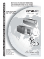
EMI RC/RH60 Installation & Operation Manual
- Type
- Installation & Operation Manual

INSTALLATION, OPERATION AND MAINTENANCE MANUAL
Enviromaster International LLC
5780 Success Dr.
Rome, NY 13440
Phone: 1-800-228-9364
Fax: 1-800-232-9364
Email: [email protected]
An ISO 9001-2000 Certified Company
P/N# 240000671, Rev. 1.6 [2/05]
COOLING ONLY/HEAT PUMP
Nominal Capacities: 9,000 -
12,000 - 15,000 - 18,000 Btuh
RC/RH 60
PACKAGED TERMINAL
AIR CONDITIONER/HEAT PUMP
Replacement for Remington, Singer, or McQuay K/EK
RC/RH60
BC60
CC60

www.retroaire.com
The Right Fit For Comfort
2
INSTALLATION, OPERATION & MAINTENANCE GUIDE
Shipping Damage MUST be Reported to the Carrier IMMEDIATELY!!!
Examine the exterior. Remove cover and examine compressor and piping for signs of damage.
SAFETY INSTRUCTIONS
Read all instructions before using the RetroAire
RC/RH60 PTAC. Install or locate this unit only in
accordance with these instructions. Use this unit
only for its intended use as described in this
manual.
Check the rating plate on the RetroAire RC/RH60
PTAC before installation to make certain the volt-
age shown is the same as the electric supply to
the unit.
The RetroAireRC/RH60 PTAC must be connected
only to a properly grounded electrical supply. Do
not fail to properly ground this unit.
Turn off the electrical supply before servicing the
RetroAire RC/RH60 PTAC.
Do not use the RetroAire RC60 PTAC if it has dam-
aged wiring, is not working properly, or has been
damaged or dropped.
[Save These Instructions]
!
!
Recognize this symbol as an indication
of important safety information
This manual is intended as an aid to qualified service per-
sonnel for proper installation, operation, and maintenance
of the RetroAire RC/RH60 Downflow Ducted PTAC. Read
these instructions thoroughly and carefully before attempt-
ing installation or operation. Failure to follow these in-
structions may result in improper installation, operation,
service or maintenance, possibly resulting in fire, electri-
cal shock, property damage, personal injury, or death.
TO THE INSTALLER
(1) Retain this manual and warranty for future refer-
ence.
(2) Before leaving the premises, review this manual
to be sure the unit has been installed correctly
and run the unit for one complete cycle to make
sure it functions properly.
To obtain technical service or warranty assistance
during or after the installation of this unit, contact
your distributor.
When calling for assistance, please have the fol-
lowing information ready:
• Model Number_________________________
• Serial Number_________________________
• Date of installation______________________
! !
DANGER
The RetroAire PTAC must:
Be connected to a properly grounded electri-
cal supply with the proper voltage as stated on
the rating plate.
Have proper over current protection (i.e. time-
delay fuse/HACR-Breaker) as listed on the Rat-
ing Plate.
Failure to follow these instructions can result in a fire,
explosion, or electrical shock causing property dam-
age, personal injury, or death.
P/N# 240000671, Rev. 1.6 [2/05]
RC/RH 60
PACKAGED TERMINAL AIR CONDITIONER/HEAT PUMP

www.retroaire.com
The Right Fit For Comfort
3
INSTALLER RESPONSIBILITIES
This manual has been prepared to acquaint you with
the installation, operation and maintenance of this
RetroAire RC/RH60 Downflow Ducted PTAC and to
provide important safety information in these areas.
We urge you to read all of the instructions thoroughly
before attempting the installation or operation of this
unit. This manual should be kept for future reference.
The manufacturer of this unit will not be liable for any
damages caused by failure to comply with the
installation and operating instructions outlined in this
manual.
A rating plate identifying this RetroAire RC/RH60
Downflow Ducted PTAC can be found on the unit.
When referring to your unit, always have the
information listed on the rating plate readily available.
Tampering with the RetroAire RC/RH60 Downflow
Ducted PTAC is dangerous and may result in
serious injury or death. Tampering voids all
warranties.
DO NOT ATTEMPT TO MODIFY OR CHANGE
THIS UNIT IN ANY WAY.
! !
DANGER
Do not use the RetroAire RC/RH60 Downflow
Ducted PTAC. With any electrical supply voltage
other then the one listed on the rating plate.
Check the rating plate on the unit for the correct
voltage rating. Failure to use the correct voltage may
result in death, serious bodily injury or property
damage. If you have any questions or doubts, consult
the factory before installing this unit.
IMPORTANT SAFETY FEATURE
Power Cord With Intergral Safety Protection
All PTACs rated 250V or less that are cord connected
to the power supply are equipped with a power cord
with intergral safety protection as standard. Providing
personal shock protection as well as arcing and fire
prevention, the device is designed to sense any
damage in the line cord and disconnect power before
a fire can occur. Tested in accordance with
Underwriters Laboratories, the cord set also offers a
unique “passive” operation, meaning the unit does
not require resetting if main power is interrupted.
WARNING - A DAMAGED POWER SUPPLY CORD
MUST BE REPLACED WITH A NEW CORD FROM
THE MANUFACTURER, AND NOT REPAIRED.
Each power cord should be checked before every
use. Follow the instructions in the order listed on
the device.
WARNING - DO NOT USE THE PRODUCT IF THE
UNIT FAILS THE TEST.
Completly read all instructions prior to assembling, op-
erating, or repairing this product. Inspect all parts for
damage prior to installation and start-up. The RetroAire
RC/RH60 Downflow Ducted PTAC must be installed
ONLY by qualified installation personnel.
! !
WARNING
MODIFICATION AND TAMPERING
!
!
DANGER
TABLE OF CONTENTS
To the Installer and Safety Instructions...........2,3
Warnings and Installer Responsibilities ............3
Controls and Components .................................4
Product Description............................................4
Electrical Wiring .................................................4
Installation Instructions ......................................5
Final Inspection and Start-Up ............................6
Specifications and Dimensions..........................7
Cleaning and Maintenance, Warranty ...............8

www.retroaire.com
The Right Fit For Comfort
4
PRODUCT DESCRIPTION
The RetroAire RC/RH60 replacement chassis is a con-
ditioner designed to allow owners of Remington, Singer,
or McQuay K/EK units to upgrade the performance of their
room conditioning and achieve current efficiency stan-
dards.
This unit is available as a cooling only model (RC60)
or, for those who wish to upgrade to a heat pump, the
RH60 chassis will fit the existing wall sleeve. The heat
pump version will reduce energy costs during periods of
outdoor temperature ranging down to as low as 40°F.
With E.E.R. as high as 9, replacement of worn out
and inefficient units becomes a very attractive option.
The RetroAire RC/RH60 cooling chassis with the
evaporator blower section can be mated with existing elec-
tric or hydronic heat sections, or replacement heat sec-
tions may be ordered as options. The control box is stan-
dard with the chassis.
Whisper quiet operation improves the room ambiance
and the 20 gauge, galvanized steel construction of the
chassis ensures long service life.
All RetroAire products are backed by Enviromaster In-
ternational LLC and are tested and rated in accordance
with ARI standards 310, 380, and UL 484. A full service
parts inventory is always available.
FACTORY INSTALLED CONTROLS
AND COMPONENTS
• Unit Mounted Operating Controls
• Thermostat
• Fan Speed Control
• Heat/Cool Switch (when applicable)
• Baffle Kit
• Weather Strip Insulation
• Foam Strip for Supply Air Duct
• Normally/Open Normally/Closed Motor Valve-
Switch, Hydronic Heat Only (standard)
FEATURES AND ACCESSORIES (Optional)
• Motorized Fresh Air Damper
• 2 or 3-Way Water Valve
• Sea Coast Coated Coils and Drain Pans
• Electric Heat (3, 4 or 5kw)
• 115V or 265/277V
• Hydronic Heat (1 or 2 row coil)
IMPORTANT: Make sure the motor valve is rated for
the correct voltage. Most RetroAire units with unit
mount controls will power a normally closed valve that is
the same voltage as the unit (ex: a unit rated 208/230V
will power a 208/230V normally closed valve). Be sure
to check the wiring diagram (located on the unit) and
voltage application for the specific unit. Other valve
configurations and voltage options are available. Con-
sult Technical Service if the unit voltage does not match
your valve application.
PREPARATION FOR INSTALLATION
1. Remove old unit from wall sleeve for proper dis-
posal.
2. Inspect wall sleeve for rust or damage, clean and
repair as necessary.
3. Remove and repair old weather seals and note
locations for new seals.
4. Make sure wall sleeve is pitched to the outside
by ½” and drain holes are open.
ELECTRICAL WIRING
A. Inspect existing wiring for any deficiencies such
as cut or frayed wires.
B. All electrical wiring must be run according to NEC
and local codes. Check the unit rating plate for
circuit ampacity and breaker or fuse size. Use
only HACR type breakers & select the proper wire
for the ampacity rating.
C. If plug and receptacle are used, check for proper
fit.

www.retroaire.com
The Right Fit For Comfort
5
13½”
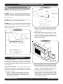
RC/RH60 BAFFLE KIT INSTALLATION
NOTE: It is very important to choose the correct baffles for
the specific job to achieve proper air circulation.
OPTION 1- (2) 1
7
/
8
” x 12
5
/
8
” tight cabinet fit baffles are in-
stalled on condenser coil by removing 2 screws on front of
condenser. Point both baffles toward center of condenser
then fasten screws.
OPTION 2- (2) 2
3
/
8
” x 12
5
/
8
” baffles used for units that are
slightly smaller than the cabinet (depth wise).
OPTION 3- (2) 4” x 12½” baffles with extensions are used
to accommodate deeper wall sleeves. Determine required
depth from cond. front to louver and adjust extension for
proper fit. (Figure 1)
FOAM SEAL INSTALLATION
FOAM STRIPS (SMALL)- ½” strips must be placed around
the supply air duct to ensure that all of the conditioned air
is delivered into the room to be conditioned. Failure to do
so could recirculate the supply air causing the unit to short
cycle. (Figure 2)
FOAM STRIPS (LARGE)- 1” x 1” strips to be positioned in
between wall sleeve and cooling chassis. This prevents
outside air from entering around the chassis from the sides
and top of the cabinet.
1. Install 1” x 1” large foam strip between wall sleeve
and cooling chassis around the condenser top and
sides to prevent outside air from entering around
the chassis into the room.
2. Place ½” x 1” foam around blower section supply
opening. This prevents conditioned air from recir-
culating. Failure to do so will result in short cy-
cling of the unit.
3. Slide blower section in place (Figure 3). The ac-
cessories kit contains (2) blower support clips to
lock blower section into position. Hook them over
flange on wall sleeve and drill screw clips to L + R
sides of blower section.
RC/RH 60 INSTALLATION INSTRUCTIONS
4. Mount control panel in space provided on cabinet.
Take deco panel (held on by two screws) off con-
trol box. Place the control box deco panel over
opening in cabinet and tighten screws through
deco panel, cabinet, and into control box.
5. Connect molex connectors from chassis, blower
and control box. Each molex connector is indi-
vidually labeled to prevent mismatching. Make
sure the label on the plugs matches the label on
the mating sockets exactly.
Figure 1
1” x 1”
Figure 2
Figure 3
Blower Section
Control Box

www.retroaire.com
The Right Fit For Comfort
6
6. Install the cooling chassis. Make sure you use the
correct condenser baffles to ensure proper air cir-
culation. Also, look at the slide rails (note that
they are set in horizontally on the cooling chassis
and wall sleeve sides). Slide cooling chassis into
place after placing correct set of baffles on front
of condenser.
NOTE: Make sure molex plugs are connected
correctly to ensure proper operation of the unit.
FINAL INSPECTION AND START-UP
A. Hard wire line voltage to control box. (All wiring
must be in accordance with NEC and local codes.)
B. Install thermostat bulb clips and grommets into coil
and position thermostat bulb into clips. Then place
air filter back on coil. (See diagram on page 7).
NOTE: When installing the control section on the
RC/RH60, you must install the thermal bulb to the
evaporator coil. To do this, take the bulb clips out
of the baffle kit bag and install on the middle of the
evaporator coil by pressing the round part of the
clips through the coil fins. Once this is done you
can proceed with the rest of the installation. See
Dimensions and Specifications (page 4) for proper
installation on the T'stat bulb.
C. Turn power on and check for proper operation of
cooling, fresh air, and heating (if supplied).
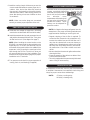
OPERATION AND MAINTENANCE
RetroAire units can be equipped with unit mounted or
remote controlled thermostats. Turning the unit
mounted thermostat knob to
the far left (red) will produce
the warmest room
temperature while turning it all
the way to the right (blue) will
produce the coolest. These
settings can be adjusted for
personal comfort.
NOTE: It is illegal to discharge refrigerant into the
atmosphere. Use proper reclaiming methods and
equipment when installing or servicing this unit.
• Regular cleaning of the air filter is required. To
access the filter (located on the evaporator coil),
remove the cabinet front and lift the filter out. It
may then be cleaned with a vacuum cleaner or
garden hose. Allowing dust to collect on the filter
will cause the unit to loose efficiency and eventu-
ally malfunction. Check filter at least once each
month.
• Vacuum dust from the return air grille surface when
cleaning the filter.
• Clean the exterior of the cabinet as desired. Use
a mild household cleaner.
• This unit is equipped with a permanently lubricated
motor. Oiling is not necessary.
TROUBLESHOOTING
If compressor will not start, check to see if the thermostat
is satisfied. If thermostat is not satisfied, check wiring and
relays for proper connections and damage.
NOTE: CR/relay = cooling relay
HR/relay = heating relay

www.retroaire.com
The Right Fit For Comfort
7
09 9200 9 8900 3.2 385/335 40/35
12 11100 8.8 10800 3.1 385/335 40/35
15 13700 8.5 13200 3 440/385 55/45
18 16300 8.2 N/A N/A 440/385 55/45
RC/RH 60 Performance Data
COP
Evaporator
CFM Hi/Lo
Fresh Air
CFM
Unit Size
Cooling
Btuh
EERs
Heat Pump
Btuh
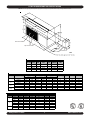
RC/RH 60 DIMENSIONS AND SPECIFICATIONS
NOTE: Due to ongoing development programs, design and specifications may change without notice.
FLA HP FLA HP RLA LRA
208/230/60/1 0.6 0.08 0.71 0.09 3.8 20 5.1 6.1 15 197
265/60/1 0.67 0.08 0.71 0.09 3.3 18.6 4.7 5.5 15 240
208/230/60/1 0.6 0.08 0.71 0.09 4.8 26.3 6.1 7.3 15 197
265/60/1 0.67 0.08 0.71 0.09 4.2 28 5.6 6.6 15 240
208/230/60/1 0.6 0.08 0.71 0.09 6.4 38 7.7 9.3 15 197
265/60/1 0.67 0.08 0.71 0.09 5.4 32 6.8 8.1 15 240
208/230/60/1 0.6 0.08 0.71 0.09 7.6 45 8.9 10.8 15 197
265/60/1 0.67 0.08 0.71 0.09 6.3 32 7.7 9.3 15 240
RC/RH 60 Electrical Specifications
Evap Motor Cond Motor Compressor
Model# Voltage/Hz/Phase Total Amps MCA Max. Fuse Min. Voltage
09
12
15
18 (RC
Only)
Heater# Voltage Watts Btuh Amps Total Heat Amps MCA Max. Fuse
208 2454 8400 11.8 12.4 15.3 20
230 3000 10300 13 13.6 16.9 20
265 3983 13600 15 15.7 19.5 20
208 3271 11200 15.7 16.3 20.3 25
230 4000 13700 17.4 18 22.3 25
265 5310 18200 20 20.7 25.7 30
208 4089 14000 19.7 20.3 25.2 30
230 5000 17100 21.7 22.3 27.8 30
3
4
5
RC/RH 60 Optional Electric Heat
13½”
Thermostat Bulb
Control Box
Clips & Grommets

www.retroaire.com
The Right Fit For Comfort
8
ALL PRODUCT LIMITED WARRANTY
Enviromaster International Corporation LLC (EMI) warrants to the purchaser/owner, that the EMI products will be free
from defects in material and workmanship under the normal use and maintenance for a period of twelve months for all
components, and (60) months on unit compressors from date of the original installation or 15 months for all components
and 63 months on unit compressors from the date of original sale whichever comes first.
WHAT WE WILL COVER
EMI will replace any defective part returned to EMI's approved service organization with a new or rebuilt part at no
charge. The replacement part assumes that unused portion of this warranty.
WHAT WE DON'T COVER
THIS WARRANTY DOES NOT INCLUDE LABOR or other costs incurred for repairing, removing, installing, shipping,
servicing, or handling of either defective or replacement parts.
EMI IS NOT RESPONSIBLE FOR
• Normal maintenance
• Damage or repairs required as a consequence of faulty installation or application by others.
• Failure to start due to voltage conditions, blown fuses, open circuit breakers, or other damages due to the
inadequacy or interruption of electrical service.
• Damage or repairs needed as a consequence of any misapplication, abuse, improper servicing, unauthorized
alteration, or improper operation.
• Damage as a result of floods, winds, fires, lightning, accidents, corrosive atmosphere, or other conditions
beyond the control of EMI.
• Parts not supplied or designated by EMI.
• Products installed outside the United States or Canada.
• Any damages to person or property of whatever kind, direct or indirect, special or consequential, whether
resulting from use or loss of use of the product.
LIMITATION OF WARRANTIES
This Warranty is exclusive and in lieu of any implied warranties of merchantability and fitness for a particular purpose and
all other warranties express or implied. The remedies provided for in this warranty are exclusive and shall constitute the
only liabilities on the part of EMI including any statements made by any individual which shall be of no effect.
FOR SERVICE OR REPAIR:
1) Contact the installer _____________________________________
2) Call the nearest distributor ________________________________
3) Call or write ___________________________________________
ENVIROMASTER INTERNATIONAL LLC
5780 Success Dr., Rome, NY 13440
Phone: 1-800-228-9364
FAX: 1-800-232-9364
Email: info@retroaire.com
-
 1
1
-
 2
2
-
 3
3
-
 4
4
-
 5
5
-
 6
6
-
 7
7
-
 8
8


EMI RC/RH60 Installation & Operation Manual
- Type
- Installation & Operation Manual
Ask a question and I''ll find the answer in the document
Finding information in a document is now easier with AI
Related papers
-
EMI RC15 Installation & Operation Manual
-
 Retro Aire RC15 Installation, Operation & Maintenance Manual
-
-
-
 Retro Aire RC85 Installation, Operation & Maintenance Manual
-
-
-
EMI RC40 Installation & Operation Manual
-
-


Other documents
-
Friedrich RC 12 User manual
-
Haier GE UAWB46A Installation guide
-
Amana TDK02 Installation guide
-
McQuay FCWC Installation and Maintenance Manual
-
-
-
-
 activTek INDUCT 500 Owner's manual
