EMI RC50 Installation & Operation Manual
- Category
- Split-system air conditioners
- Type
- Installation & Operation Manual

P/N# 240004174, Rev. 1.4 [02/05]
Enviromaster International LLC
5780 Success Dr.
Rome, NY 13440
Phone: 1-800-228-9364
Fax: 1-800-232-9364
Email: [email protected]
INSTALLATION, OPERATION AND MAINTENANCE MANUAL
An ISO 9001-2000 Certified Company
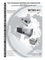
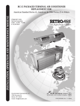
RC50 PACKAGED TERMINAL AIR CONDITIONER
Replacement For:
Dunham/Bush Newport Models I, II, III, and IV
STRAIGHT COOL ONLY
Nominal Capacities:
9,000 - 12,000 - 15,000
& 18,000 Btuh
RC50
CC50
BC50

www.retroaire.com
The Right Fit For Comfort
2
RC50 PACKAGED TERMINAL REPLACEMENT AIR CONDITIONER
INSTALLATION, OPERATION, AND MAINTENANCE GUIDE
P/N# 240002990, Rev. 1.4 [02/05]
SAFETY INSTRUCTIONS
Read all instructions before using the RetroAire
RC50 PTAC. Install or locate this unit only in accor-
dance with these instructions. Use this unit only for
its intended use as described in this manual.
Check the rating plate on the RetroAire RC50 PTAC
before installation to make certain the voltage shown
is the same as the electric supply to the unit.
The RetroAire RC50 PTAC must be connected only
to a properly grounded electrical supply. Do not fail
to properly ground this unit.
Turn off the electrical supply before servicing the
RetroAire RC50 PTAC.
Do not use the RetroAire RC50 PTAC if it has dam-
aged wiring, is not working properly, or has been
damaged or dropped.
[Save These Instructions]
This manual is intended as an aid to qualified service
personnel for proper installation, operation, and maintenance
of the RetroAire RC50 Packaged Terminal Air Conditioner.
Read these instructions thoroughly and carefully before
attempting installation or operation. Failure to follow these
instructions may result in improper installation, operation,
service, or maintenance, possibly resulting in fire, electrical
shock, property damage, personal injury, or death.
TO THE INSTALLER
(1) Retain this manual and warranty for future refer-
ence.
(2) Before leaving the premises, review this manual to
be sure the unit has been installed correctly and
run the unit for one complete cycle to make sure it
functions properly.
To obtain technical service or warranty assistance
during or after the installation of this unit, contact
your local representative. Visit our website
www.retroaire.com for a local representative list-
ing. For further assistance call 1-800-228-9364.
When calling for assistance, please have the fol-
lowing information ready:
• Model Number_________________________
• Serial Number_________________________
• Date of installation______________________
Shipping Damage MUST be Reported to the Carrier IMMEDIATELY!!!
Examine the exterior. Remove cover and examine compressor and piping for signs of damage.
!
!
Recognize this symbol as an indication
of important safety information
!
!
DANGER
The RetroAire PTAC must:
Be connected to a properly grounded elec-
trical supply with the proper voltage as
stated on the rating plate.
Have proper over current protection (i.e.
time- delay fuse/HACR-Breaker) as listed on
the Rating Plate.
Failure to follow these instructions can result in a
fire, explosion, or electrical shock causing prop-
erty damage, personal injury, or death.

www.retroaire.com
The Right Fit For Comfort
3
TABLE OF CONTENTS
To the Installer and Safety Instructions ............ 2,3
Warnings and Installer Responsibilities...............3
Controls and Components ...................................4
Product Description, Capacities, Air System .....4
Electrical Wiring..................................................5
Installation Instructions ................................... 6,7
Final Inspection and Start-Up .............................. 8
Sequence of Operation and Maintenance... 8, 9,10
Troubleshooting................................................. 10
Specifications and Dimensions ......................... 11
Warranty ........................................................... 12
INSTALLER RESPONSIBILITIES
This manual has been prepared to acquaint you with the
installation, operation and maintenance of this RetroAire
RC50 PTAC and to provide important safety information in
these areas.
We urge you to read all of the instructions thoroughly before
attempting the installation or operation of this unit. This
manual should be kept for future reference.
The manufacturer of this unit will not be liable for any damages
caused by failure to comply with the installation and operating
instructions outlined in this manual.
A rating plate identifying this RetroAire RC50 PTAC can be
found on the unit. When referring to your unit, always have
the information listed on the rating plate readily available.
MODIFICATION AND TAMPERING
IMPORTANT SAFETY FEATURE
Power Cord With Intergral Safety Protection
All PTACs rated 250V or less that are cord connected
to the power supply are equipped, with a power cord
with intergral safety protection as standard. Providing
personal shock protection as well as arcing and fire
prevention. The device is designed to sense any
damage in the line cord and disconnect power before
a fire can occur. Tested in accordance with
Underwriters Laboratories, the cord set also offers a
unique “passive” operation, meaning the unit does not
require resetting if main power is interrupted.
WARNING - A DAMAGED POWER SUPPLY CORD
MUST BE REPLACED WITH A NEW CORD FROM
THE MANUFACTURER, AND NOT REPAIRED.
Each power cord should be checked before every use.
Follow the instructions in the order listed on the device.
WARNING - DO NOT USE THE PRODUCT IF THE
UNIT FAILS THE TEST.
!
!
WARNING
Completely read all instructions prior to assembling,
installing, operating, or repairing this product. In-
spect all parts for damage prior to installation
and start-up. The RetroAire RC50 PTAC must
be installed ONLY by qualified installation per-
sonnel.
!
!
DANGER
Tampering with the RetroAire RC50 PTAC is dan-
gerous and may result in serious injury or death.
Tampering voids all warranties. Do not attempt to
modify or change this unit in any way.

www.retroaire.com
The Right Fit For Comfort
4
PRODUCT DESCRIPTION
The RetroAire RC50 is a packaged terminal air conditioner
designed to allow owners of Dunham/Bush Newport models
I, II, III, IV to upgrade the performance of their room air con-
ditioning and achieve significant efficiency improvement.
This unit is available as a cooling-only model and energy
efficiency ratings as high as 9.0 can mean rapid payback of
your replacement investment through energy savings.
The RC50 features two fan speeds and a manual fresh air
damper. Because the outdoor fan is separate, it does not
run in venting or heating modes, thereby saving energy. Whis-
per quiet operation improves room ambience and a wash-
able, permanent filter makes service a snap. The 20 gauge
galvanized steel construction of the chassis ensures long
service life.
AIR SYSTEM
• Motors are PSC type with overheat protection.
• Blower deck air stream surfaces are insulated with 1/4”
fiberglass or 1/8” volara.
• Filter is washable, permanent, and accessible without
tools.
HIGH-EFFICIENCY HEAT EXCHANGER
Coil is seamless rifled copper tubing arranged in staggered
configuration with enhanced aluminum fins and tested to
400 psig. The tubes are mechanically expanded for secure
bonding to fin shoulders.
CONDENSER SECTION AND
REFRIGERATION CIRCUIT
• High efficiency rotary compressor with a five year war-
ranty (standard)
• Automatic expansion valve for low-ambient protection
STANDARD CONTROLS AND COMPONENTS
• Unit Mounted Operating Controls
- Thermostat
- Fan Speed Control
- Heat/Cool System Switch
• Continuous/Cycling Fan Control Switch
(unit mount only)
• Manual Fresh Air Damper (RC50 chassis)
• Weather Strip Insulation
• Condenser Duct Kit (field installed)
IMPORTANT: To ensure proper duct supply, duct depth
should have been identified prior to ordering. Verify duct
depth as described under chassis installation in these in-
structions.
OPTIONS & ACCESSORIES
• Electric Heat (field installed) See Spec & Performance
on pg. 11
• 24V Remote Thermostat
• Hydronic Heat Coil
• Hydronic Coil Freeze Protection
• 2 or 3-Way Water Valve
• Sea Coast Coated Coils and Drain Pans

www.retroaire.com
The Right Fit For Comfort
5
ELECTRICAL WIRING
1. Inspect existing wiring for any deficiencies such as cut
or frayed wires.
2. All electrical wiring must be run according to NEC and
local codes. Check the unit rating plate for circuit
ampacity and breaker or fuse size. Use only HACR type
breakers and select the proper wire for ampacity rating.
3. If plug and receptacle are used, check for proper fit.
REMOTE THERMOSTAT UNITS RATED 208/230V
Units that are factory wired for remote thermostat and rated
208/230V utilize a multi-tap, low volt transformer for the con-
trol circuit. The transformer has separate voltage taps for
208V and 230V supply voltages and is factory shipped wired
for 230V. If the actual measured power supply voltage is
less than 210 Volts, it is recommended that the transformer
tap be changed to the 208V transformer tap.
WARNING!! To avoid possible injury or death due
to electrical shock, disconnect the power supply
by unplugging the line cord or switching off the
breaker switch to the unit prior to changing the
transformer tap.
With the power completely disconnected from the unit, re-
move the control cover and locate the control transformer.
The high Volt transformer taps are color-coded Orange for
230V and Red for 208V field supply voltage. Remove the
orange tap from its location, clip the terminal and place a
wire nut on the end to keep it insulated. Next, locate the
Red transformer wire, crimp on an appropriate connector and
place it back on the terminal from which the orange wire
came. Finally, replace the control box cover and test the
unit.
RATING AND TESTING
The RetroAire RC50 is tested and rated in accordance with
ARI standards 310/380 and UL 484. Due to ongoing devel-
opment programs, design and specifications may change
without notice.
WARRANTY
All RetroAire products are covered under standard warranty
and are backed by Enviromaster International, LLC.
PREPARATION FOR INSTALLATION
WARNING!! To avoid possible injury or death due
to electrical shock, open the power supply
disconnect switch and secure it in an open position
during installation. On a plug and receptacle
connection, keep the unit unplugged until
installation is complete.
1. Remove old unit from wall sleeve for proper disposal.
2. Inspect wall sleeve for rust or damage, clean and repair
as necessary.
3. Remove and repair old weather seals and note loca-
tions for new seals.
4. Make sure wall sleeve is pitched to the outside by 1/2”
and drain holes are open.

www.retroaire.com
The Right Fit For Comfort
6
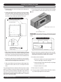
Wall Sleeve Bottom Section
Left and Right Condenser Ducts
1. Remove unit from carton and inspect the cooling chas-
sis for damage.
2. Inspect the outdoor side (condenser) for proper installa-
tion of foam tapes and sealing compound, there should
be a 1/2” x 1/2” closed cell foam tape gasket around the
perimeter of the condenser side face of the unit.
RC50 INSTALLATION INSTRUCTIONS
CHASSIS INSTALLATION
6. The cooling chassis must have condenser ducts installed
to the condenser coil face to prevent any air re-circula-
tion.
3. Also, there will be factory installed sealing compound
placed on either side of the condenser side flange, around
the notches, to prevent premature overflow of condensa-
tion, in the event of excess water on the condenser side.
4. Prepare the wall sleeve for installation by removing ALL
gasket material and clean the surface where the cooling
chassis face will butt against the wall sleeve.
5. Clean out all debris from wall sleeve and drainage holes.
inspect for cracks, holes, rust, etc., and repair (if neces-
sary).
The existing wall sleeve (condenser side) may have a center
baffle (air splitter), ensure the bottom section of this baffle
has a notch in place to allow the drip edge on the chassis to
hang over the wall sleeve bottom flange. If it does not, snip
and bend away enough metal to provide at least 1” clearance
away from chassis drip edge.
IMPORTANT: Verify depth of ducts by installing the unit and
measuring from the face of the condenser coil to the outdoor
louver.
7. Retrieve the factory supplied condenser ducts and de-
termine Left from Right as shown above. note that the
end flanges will both point inward when installed.
8. Condenser duct installation.
a. Remove (2) bottom coil screws (approximately 2”
from the drip edge on the left and right).
b. Hook top flange of duct behind chassis top flange
and secure with screw.
c. Replace bottom coil screws.
9. Slide chassis into position
10. Using pry-angles, located on either side of the chassis,
pry chassis tight against the wall sleeve.
RetroAire RC50 Chassis Base Pan
Existing Wall Sleeve Condenser Side
1/2” X 1/2” Closed-Cell Foam
Tape (field installed)
VERY IMPORTANT: Base flange must
extend over the existing wall sleeve
flange to ensure proper condensate
overflow drainage.
Wall Sleeve Section View
Condenser Ducts - Top View

www.retroaire.com
The Right Fit For Comfort
7
IMPORTANT: Ensure that the chassis drip edge extends off the
wall sleeve bottom flange for proper drainage of condensate.
11. After installation, fill base pan with water and run unit
to ensure condensate will flow out of the chassis and
into the wall sleeve properly, if there is water leakage,
repeat step 10.
BLOWER SECTION (BC50)
1. Remove old blower deck and install new blower deck
with existing thumb-screws or factory supplied thumb-
screws.
2. Ensure that wire routing will not interfere with the chas-
sis removal.
CHASSIS INSTALLATION (RC50) Continued
CONTROL SECTION (CC50)
1. Remove old control box and install new box using same
thumb screws.
2. Refer to wire diagram to wire blower section and heating
element.
3. Plug in all sections to the control box (chassis and blower
section), per the wire diagram.
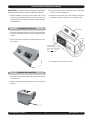
4. Install thermostat bulb clips with rubber grommets to
evaporator coil face and position bulb in these clips.
5. Install foam air filter to Velcro strips.
T’Stat Bulb
(Mount W/Clips and
ensure that the bulb
does not come in
contact with coil)
Blower Deck
Control
Box

www.retroaire.com
The Right Fit For Comfort
8
3. Place system switch in the “OFF” position. All opera-
tion should stop.
CAUTION!! Avoid rotating the thermostat knob back
and forth from heating to cooling. This causes the com-
pressor to cycle on and off rapidly and will cause dam-
age to the compressor. Allow the compressor to remain
off for at least three minutes prior to restarting the unit.
HEATING CYCLE - ELECTRIC
1. Place system switch in the “HEAT” position.
2. Rotate thermostat knob counter-clockwise until the in-
door fans start and the electric coil starts emitting heat.
The condenser fan does not run during the heating cycle.
After the unit starts and the area gets warmer, turn the
thermostat knob clockwise until a slight click is heard
and the electric heater turns off. If a warmer room tem-
perature is desired, continue turning the knob counter-
clockwise and let the unit continue operating. If a cooler
room temperature is desired, rotate the thermostat knob
clockwise until the electric heater cycles off.
IMPORTANT: Room temperature must be below 85º F to
energize the heater.
3. Place system switch in the “OFF” position. All opera-
tion should stop.
HYDRONIC COIL
The coil with the old unit can be located in the subbase,
under the chassis in a special attachment, or above the chas-
sis in a special attachment. It is necessary to know where
the coil is to be located and the physical size of the coil so
the right coil can be supplied if ordered for replacement. The
coil is shipped loose for field installation. It should be in-
stalled in the same manner as the existing coil. when the
hydronic coil is not replaced, installation of the chassis should
follow the instructions in this manual.
FINAL INSPECTION AND START-UP
1. Make sure the chassis is level. check by pouring water
into the drain pan and making certain it flows through
the drain hoses to the condenser side of the unit.
2. Plug in or hard wire line voltage to unit.
IMPORTANT: Follow the information provided on the rating
plate for voltage and amperage/fuse size for proper supply.
3. Attach the front panel to the existing cabinet enclosure.
4. Turn the power on.
5. Check for proper operation (i.e., cooling, optional fresh
air, and heating if supplied).
6. Check to be sure nothing will interfere with the room
discharge air or the return air to the units (i.e., curtains
or drapes that obstruct the air flow or plush carpeting
that can obstruct the return air). Items like these can
cause serious damage to the chassis and can void the
warranty.
SEQUENCE OF OPERATION
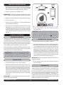
THERMOSTAT CONTROLS
The RetroAire RC50 can be equipped with unit mount controls
or remote thermostats. Turning the unit mount thermostat
knob to the far left will produce the warmest room temperature
while turning it all the way to the right will produce the coolest.
These settings can be adjusted for personal comfort.
Units with remote thermostats will require operation accord-
ing to standard thermostat settings. Refer to the operating
instructions for specific thermostat used.
CAUTION!! When the unit is first powered up, high
humidity conditions can cause condensation to form
on the discharge grill. Keep doors and windows closed
to reduce humidity and condensation will evaporate.
COOLING CYCLE
1. Place system switch in the “COOL” position.
2. Rotate thermostat knob (above) clockwise until the com-
pressor and fans start and cold air begins to flow from
the unit. For a colder room temperature, continue turn-
ing the thermostat knob clockwise and let the unit con-
tinue operating to cool the room and remove humidity. If
a warmer room temperature is desired, rotate the ther-
mostat knob counter-clockwise until the compressor
cycles off.
IMPORTANT: The room temperature must be above 65º F
for the compressor to operate.
FAN SPEED SWITCH
SYSTEM
SWITCH
THERMOSTAT KNOB

www.retroaire.com
The Right Fit For Comfort
9
CLEANING AND MAINTENANCE
WARNING!! The RetroAire RC50 is designed and
constructed for reliability and long life with
minimal maintenance but service or repairs should
only be performed by qualified service personnel.
CLEANING THE INTERIOR OF THE UNIT
1. Disconnect power from unit.
2. Remove access panels and do a visual inspection of
the unit, making sure to check for obvious problems
such as damaged coils or evidence of extended wear
on any moving part.
3. Check for unusual odors, oil leaks, or stains on or around
the coil and refrigerant lines. The presence of oil here
may indicate a potentially serious problem such as a
refrigerant leak.
4. Inspect all electrical connections. look for frayed wires
and poor connections. Terminal ends that are loose will
eventually fail, causing a loss of performance or worse.
5. Check fan motors and blower assemblies. Check set-
screws and motor mounting hardware, making sure they
are tight.
6. Brush and/or vacuum the centrifugal fan blades and
blower cage assemblies. These parts must be clean to
operate efficiently.
7. Inspect and clean the indoor and outdoor coils, using a
fin comb, if necessary, to straighten any damaged fins.
These coils must be clean for proper operation.
IMPORTANT: Do not use a solvent-based cleaner on the
indoor or outdoor coils. Some solvents can produce a
noxious odor when starting the fan or electric heat.
8. Inspect and clean the drain pan drainline (if any) use of
an anti-fungicide tablet is recommended to keep the
condensate system free from bacterial contaminants.
9. Check weep holes along the rear flange of the base pan,
making sure they are open.
10. Check the pitch of the unit. Over time, the building and
equipment may settle, causing a shift in the direction of
the condensate flows. Ideally the unit should pitch a
minimum of 5° (at least ½”) to the outside to allow for
proper drainage.
11. Replace panels and reconnect electeical power.
12. Test unit operation.
HEATING CYCLE - HYDRONIC
The RetroAire RC50 is equipped with a hydronic heat option.
The unit is provided with a two-position molex plug for motor
valve connection. To wire this option, take the molex plug
connector with (2) yellow wires from the kit and plug it into
the molex on the unit. Then wire the opposite end of the
molex to the motorized valve in the hydronic circuit.
IMPORTANT: Make sure the motor valve is rated for the
correct voltage. RetroAire units with unit mount controls will
power a valve that is the same voltage as the unit (ex: a unit
rated 208/230V will power a 208/230V valve). Other voltage
options are available. Be sure that the value you are using
matches the unit.
A. Place system switch in “HEAT” position.
B. Turn thermostat knob counter-clockwise. Motorized valve
should open and allow hot water to run through the coil.
The indoor fans will run, blowing air through the hydronic
coil.
C. Check room Comfort level as outlined under “Heating
Cycle - Electric.”
CONTINUOUS/CYCLING FAN CONTROL SWITCH
(Unit Mount Only)
This option allows the operator of the RetroAire RC50 to
have the evaporator fan cycle or run continuously. With the
switch in the cycling position the evaporator fan will only run
when the unit calls for heat or cooling. When the switch is in
the “CONSTANT” position, the evaporator fan will run con-
tinuously unless the system switch is turned off.
IMPORTANT: In heating mode, the indoor fan will continue
to run for a short time after the call for heat has ceased to
purge the unit of remaining heat for improved efficiency. This
feature will only operate in cycling fan mode if the fan switch
is in the “OFF” position. Otherwise, the fan will operate con-
tinuously.
CONDENSATE REMOVAL
The RetroAire RC50 is equipped with a slinger ring prop that
allows the unit to pick up condensate in the base pan and
sling it on the hot condenser coil for re-evaporation.
AQUASTAT CONNECTION
The RetroAire RC50 is supplied with a standard aquastat
connection. The connection is located on the bottom or side
with a black jumper wire installed in molex. To wire option
take jumper wire and cut in half. Then connect two field sup-
plied wires to the cut ends of jumper and wire to aquastat
(see wiring diagram for more information). If option is not
being used simply leave jumper wire connected to unit.
SEQUENCE OF OPERATION Continued

www.retroaire.com
The Right Fit For Comfort
10
FOR SERVICE OR REPAIR
When calling RetroAire
for service assistance and/or parts
orders you will need to provide: complete unit model number
and complete serial number. This information can be ob-
tained from the rating plate attached to the equipment.
For your convenience record at time of installation:
Model#
_________________________________________________
Serial #
_________________________________________________
Date Installed
_________________________________________________
CLEANING THE EXTERIOR OF THE UNIT
1. Clean the air filter at least once a month by removing it
from the unit and washing or vacuuming any dust from
its surface. Allowing dust to collect on the filter will cause
the PTAC to lose efficiency and eventually malfunction.
2. When cleaning the filter, be sure to vacuum any dust
from the return air grille surface as well.
3. Clean exterior of the cabinet as desired with a mild soap
or household cleaner.
IMPORTANT: If a new air filter is needed for your RetroAire
RC50, consult factory for availability and/or proper sizing.
TROUBLESHOOTING
DANGER!! Before servicing the RetroAire RC50, be
sure to turn off electrical power to the unit. Failure
to do so can result in a fire, explosion or electrical
shock causing property damage, personal injury
or death.
NO HEAT OR COOLING
Check to see if the unit has power and if the thermostat is
satisfied. if the thermostat is not satisfied, refer to the wiring
diagram and check control components for continuity.
CLEANING AND MAINTENANCE Continued

www.retroaire.com
The Right Fit For Comfort
11
T’Stat Bulb (Mount W/Clips and ensure that the bulb does not
come in contact with coil)
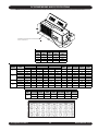
RC50 DIMENSIONS AND SPECIFICATIONS
NOTE: Due to ongoing product development, design, specifications, and performance data may change without notice.
HEATER
NO.
VOLTAGE WATTS BTUH AMPS
TOTAL
HEAT AMPS
MCA MAX FUSE
208 3,200 11,000 15.4 16.0 19.8 20
230 3,900 13,400 17.0 17.6 21.8 25
3
OPTIONAL ELECTRIC HEAT SPECIFICATIONS
UNIT
SIZE
COOLING
BTUH
EER
EVAP CFM
HI/LO
FRESH AIR
CFM
09 9,200 9.0 385/335 40/35
12 11,100 8.8 385/335 40/35
15 13,700 8.5 440/385 55/45
18 16,300 8.2 440/385 55/45
RC50 PERFORMANCE DATA
FLA HP FLA HP RLA LRA
115/60/1 1.4
0.09 1.25 0.1
7.4 44 10.1 11.9
15
104 5-15P
208/230/60/1 0.6
0.08 0.71 0.09
3.8 20 5.1 6.1
15
197 6-15P
265/60/1 0.67 0.08 0.71 0.09 3.3 18.6 4.7 5.5 15 240 7-20P
115/60/1 1.4
0.09 1.25 0.1
9.7 54 12.4 14.8
20
104 5-20P
208/230/60/1 0.6
0.08 0.71 0.09
4.8 26.3 6.1 7.3
15
197 6-15P
265/60/1 0.67 0.08 0.71 0.09. 4.2 28 5.6 6.6 15 240 7-20P
208/230/60/1 0.6
0.08 0.71 0.09
6.4 38 7.7 9.3
15
197 6-15P
265/60/1 0.67 0.08 0.71 0.09 5.4 32 6.8 8.1 15 240 7-20P
208/230/60/1 0.6
0.08 0.71 0.09
7.6 45 8.9 10.8
15
197 6-15P
265/60/1 0.67
0.08 0.71 0.09
6.3 32 7.7 9.3
15
240 7-20P
ELECTRICAL SPECIFICATIONS
15
18
MIN
VOLTS
LINE
CORD
9
12
COMPRESSOR TOTAL
AMPS
MCA MAX FUSE
MODEL
NUMBER
VOLTS/HZ/PH
ASE
EVAP MOTOR COND MOTOR
NEMA SPECIFICATIONS [NON-LOCKING RECEPTACLES]

www.retroaire.com
The Right Fit For Comfort
12
ALL PRODUCT LIMITED WARRANTY
Enviromaster International LLC (EMI) warrants to the purchaser/owner that EMI products will be free from
defects in material and workmanship under the normal use and maintenance for a period of twelve months
for all components and sixty months on unit compressors from the date of original installation, or fifteen
months for all components and sixty-three months on unit compressors from the date of manufacture,
whichever comes first.
WHAT WE WILL COVER
EMI will replace any defective part returned to EMI's approved service organization with a new or rebuilt part
at no charge. The replacement part assumes that unused portion of this warranty.
WHAT WE DON'T COVER
THIS WARRANTY DOES NOT INCLUDE LABOR or other costs incurred for repairing, removing, installing,
shipping, servicing, or handling of either defective or replacement parts.
EMI IS NOT RESPONSIBLE FOR:
• Normal maintenance
• Damage or repairs required as a consequence of faulty installation or application by others.
• Failure to start due to voltage conditions, blown fuses, open circuit breakers, or other damages
due to the inadequacy or interruption of electrical service.
• Damage or repairs needed as a consequence of any misapplication, abuse, improper servicing,
unauthorized alteration, or improper operation.
• Damage as a result of floods, winds, fires, lightening, accidents, corrosive atmosphere, or other
conditions beyond the control of EMI.
• Parts not supplied or designated by EMI.
• Products installed outside the United States or Canada.
• Any damages to person or property of whatever kind, direct or indirect, special or consequential,
whether resulting from use or loss of use of the product.
LIMITATION OF WARRANTIES
This warranty is exclusive and in lieu of any implied warranties of merchantability and fitness for a particular
purpose and all other warranties express or implied. The remedies provided for in this warranty are exclusive
and shall constitute the only liabilities on the part of EMI including any statements made by any individual
which shall be of no effect.
FOR SERVICE OR REPAIR:
(1) Contact the Installer
(2) Call the Nearest Distributor
(3) Call or Write:
ENVIROMASTER INTERNATIONAL LLC
5780 Success Dr., Rome, NY 13440
Phone: 1-800-228-9364
FAX: 1-800-232-9364
Email: info@retroaire.com
-
 1
1
-
 2
2
-
 3
3
-
 4
4
-
 5
5
-
 6
6
-
 7
7
-
 8
8
-
 9
9
-
 10
10
-
 11
11
-
 12
12


EMI RC50 Installation & Operation Manual
- Category
- Split-system air conditioners
- Type
- Installation & Operation Manual
Ask a question and I''ll find the answer in the document
Finding information in a document is now easier with AI
Related papers
-
EMI RC15 Installation & Operation Manual
-
 Retro Aire RC15 Installation, Operation & Maintenance Manual
-
-
EMI RC40 Installation & Operation Manual
-
-
-
-
-
-

Other documents
-
Broan Drip Baffle Kit for Micro Channel Coils Installation guide
-
Friedrich PDE09K3SF Owner's manual
-
-
Sharp HP-BC50 User manual
-
 Friedrich Air Conditioning PDE07K3SG Owner's manual
-
-
Samsung AC100RXADKG/EU User guide
-
Cardiostrong CST-BC50 Assembly And Operating Instructions Manual
-
 puravent CC50 User manual
-
White Rodgers 10C17E-410 Owner's manual

