Page is loading ...

THIS MANUAL MUST ACCOMPANY THE EQUIPMENT AT ALL TIMES.
To find the latest revision of this
publication, visit our website at:
www.mqpower.com
WHISPERWATT™ SERIES
MODEL DCA220SSJU4F
60Hz GENERATOR
(JOHN DEERE 6068HFG09 DIESEL ENGINE)
Revision #4 (01/24/18)
OPERATION MANUAL

PAGE 2 — DCA220SSJU4F 60 HZ GENERATOR • OPERATION MANUAL — REV. #4 (01/24/18)
PROPOSITION 65 WARNING
Diesel engine exhaust and some of

DCA220SSJU4F 60 HZ GENERATOR• OPERATION MANUAL — REV. #4 (01/24/18) — PAGE 3
TABLE OF CONTENTS
DCA220SSJU4F 60 Hz-
GENERATOR
Proposition 65 Warning ........................................... 2
Safety Information .............................................. 5-10
Specifications ........................................................ 11
Dimensions ............................................................ 12
Installation ........................................................ 13-14
General Information ............................................... 15
General Paralleling Information (Option) .......... 16-18
Major Components ................................................ 19
Engine Controller Unit (ECU 835) ......................... 20
Engine/Generator Control Panel............................ 21
Basler Digital Genset Controller (Option) ......... 22-23
Paralleling Panel (Option) ................................. 24-25
Output Terminal Panel Familiarization .............. 26-28
Load Application .................................................... 29
Generator Outputs ............................................ 30-31
Gauge Reading ..................................................... 31
Output Terminal Panel Connections ................. 32-33
Inspection/Setup ............................................... 34-37
Generator Start-Up Procedure (Manual) .......... 38-39
Generator Start-Up Procedure (Auto Mode) .......... 40
Generator Shut-Down Procedures ........................ 41
Maintenance ..................................................... 42-49
Generator Wiring Diagram ..................................... 50
Generator Wiring Diagram, Basler (Option) ........... 51
Engine Wiring Diagram (ECU 835) ........................ 52
Engine Wiring Diagram
(Basler DGC2020HD Option) ................................ 53
3Ø-480 VAC Parallel Wiring Diagram .................... 55
3Ø-208 VAC Parallel Wiring Diagram .................... 56
Battery Charger Wiring Diagram (Option) ............. 57
Water Heating Element Wiring Diagram (Option) .. 58
Troubleshooting (Generator) .................................. 59
Troubleshooting Diagnostics ................................. 60
Basler DGC-2020 Programming Appendix ...... 61-78
NOTICE
Specifications are subject to change without notice.

PAGE 4 — DCA220SSJU4F 60 HZ GENERATOR • OPERATION MANUAL — REV. #4 (01/24/18)
NOTES

DCA220SSJU4F 60 HZ GENERATOR• OPERATION MANUAL — REV. #4 (01/24/18) — PAGE 5
SAFETY INFORMATION
Do not operate or service the equipment before reading the
entire manual. Safety precautions should be followed at all
times when operating this equipment. Failure to read and
understand the safety messages and operating instructions
could result in injury to yourself and others.
SAFETY MESSAGES
The four safety messages shown below will inform you
about potential hazards that could injure you or others. The
safety messages specifi cally address the level of exposure
to the operator and are preceded by one of four words:
DANGER, WARNING, CAUTION
or NOTICE.
SAFETY SYMBOLS
DANGER
Indicates a hazardous situation which, if not avoided,
WILL result in DEATH or SERIOUS INJURY.
WARNING
Indicates a hazardous situation which, if not avoided,
COULD result in DEATH or SERIOUS INJURY.
CAUTION
Indicates a hazardous situation which, if not avoided,
COULD result in MINOR or MODERATE INJURY.
NOTICE
Addresses practices not related to personal injury.
Potential hazards associated with the operation of this
equipment will be referenced with hazard symbols which
may appear throughout this manual in conjunction with
safety messages.

PAGE 6 — DCA220SSJU4F 60 HZ GENERATOR • OPERATION MANUAL — REV. #4 (01/24/18)
SAFETY INFORMATION
GENERAL SAFETY
CAUTION
NEVER operate this equipment without proper protective
clothing, shatterproof glasses, respiratory protection,
hearing protection, steel-toed boots and other protective
devices required by the job or city and state regulations.
NEVER operate this equipment when not
feeling well due to fatigue, illness or when
under medication.
NEVER operate this equipment under the infl uence of
drugs or alcohol.
ALWAYS check the equipment for loosened threads or
bolts before starting.
DO NOT use the equipment for any purpose other than
its intended purposes or applications.
NOTICE
This equipment should only be operated by trained and
qualifi ed personnel 18 years of age and older.
Whenever necessary, replace nameplate, operation and
safety decals when they become diffi cult read.
Manufacturer does not assume responsibility for any
accident due to equipment modifi cations. Unauthorized
equipment modifi cation will void all warranties.
NEVER use accessories or attachments that are not
recommended by MQ Power for this equipment. Damage
to the equipment and/or injury to user may result.
ALWAYS know the location of the nearest
fi re extinguisher.
ALWAYS know the location of the nearest
fi rst aid kit.
ALWAYS know the location of the nearest
phone or keep a phone on the job site.
Also, know the
phone numbers of the nearest ambulance, doctor
and
fi re department.
This information will be invaluable in
the case of an emergency.
GENERATOR SAFETY
DANGER
NEVER operate the equipment in an explosive
atmosphere or near combustible materials. An
explosion or fi re could result causing severe
bodily harm or even death.
WARNING
NEVER disconnect any
emergency or safety devices.
These devices are intended for operator safety.
Disconnection of these devices can cause severe injury,
bodily harm or even death. Disconnection of any of these
devices will void all warranties.
CAUTION
NEVER
lubricate components or attempt service on a
running machine.
NOTICE
ALWAYS ensure generator is on level ground before use.
ALWAYS keep the machine in proper running condition.
Fix damage to machine and replace any broken parts
immediately.
ALWAYS
store equipment properly when it is not being
used. Equipment should be stored in a clean, dry location
out of the reach of children and unauthorized personnel

DCA220SSJU4F 60 HZ GENERATOR• OPERATION MANUAL — REV. #4 (01/24/18) — PAGE 7
SAFETY INFORMATION
ENGINE SAFETY
DANGER
The engine fuel exhaust gases contain poisonous carbon
monoxide. This gas is colorless and odorless, and can
cause death if inhaled.
The engine of this equipment
requires an adequate free
fl ow of cooling air. NEVER
operate this equipment in
any enclosed or narrow area
where free fl ow of the air is
restricted. If the air fl ow is
restricted it will cause injury to people and property and
serious damage to the equipment or engine.
WARNING
DO NOT place hands or fingers inside engine
compartment when engine is running.
NEVER operate the engine with heat shields or
guards removed.
Keep fi ngers, hands hair and clothing away
from all moving parts to prevent injury.
DO NOT remove the radiator cap while the
engine is hot. High pressure boiling water
will gush out of the radiator and severely
scald any persons in the general area of
the generator.
DO NOT remove the coolant drain plug while the engine
is hot. Hot coolant will gush out of the coolant tank and
severely scald any persons in the general area of the
generator.
DO NOT remove the engine oil drain plug while the
engine is hot. Hot oil will gush out of the oil tank and
severely scald any persons in the general area of the
generator.
CAUTION
NEVER touch the hot exhaust manifold,
muffl er or cylinder. Allow these parts to cool
before servicing equipment.
NOTICE
NEVER
run engine without an air fi lter or with a dirty air
fi lter. Severe engine damage may occur. Service air fi lter
frequently to prevent engine malfunction.
NEVER tamper with the factory settings
of the engine or engine governor. Damage
to the engine or equipment can result
if operating in speed ranges above the
maximum allowable.
Wet stacking is a common problem with diesel engines
which are operated for extended periods with light or
no load applied. When a diesel engine operates without
suffi cient load (less than 40% of the rated output), it will
not operate at its optimum temperature. This will allow
unburned fuel to accumulate in the exhaust system,
which can foul the fuel injectors, engine valves and
exhaust system, including turbochargers, and reduce
the operating performance.
In order for a diesel engine to operate at peak effi ciency,
it must be able to provide fuel and air in the proper ratio
and at a high enough engine temperature for the engine
to completely burn all of the fuel.
Wet stacking does not usually cause any permanent
damage and can be alleviated if additional load is
applied to relieve the condition. It can reduce the system
performance and increase maintenance. Applying an
increasing load over a period of time until the excess
fuel is burned off and the system capacity is reached
usually can repair the condition. This can take several
hours to burn off the accumulated unburned fuel.
State Health Safety Codes and Public Resources
Codes specify that in certain locations, spark arresters
must be used on internal combustion engines that use
hydrocarbon fuels. A spark arrester is a device designed
to prevent accidental discharge of sparks or fl ames
from the engine exhaust. Spark arresters are qualifi ed
and rated by the United States Forest Service for this
purpose. In order to comply with local laws regarding
spark arresters, consult the engine distributor or the
local Health and Safety Administrator.

PAGE 8 — DCA220SSJU4F 60 HZ GENERATOR • OPERATION MANUAL — REV. #4 (01/24/18)
SAFETY INFORMATION
FUEL SAFETY
DANGER
DO NOT start the engine near spilled fuel or combustible
fl uids. Diesel fuel is extremely fl ammable and its vapors
can cause an explosion if ignited.
ALWAYS refuel in a well-ventilated area, away from
sparks and open fl ames.
ALWAYS use extreme caution when working with
fl ammable liquids.
DO NOT fi ll the fuel tank while the engine is running
or hot.
DO NOT overfi ll tank, since spilled fuel could ignite if it
comes into contact with hot engine parts or sparks from
the ignition system.
Store fuel in appropriate containers, in well-ventilated
areas and away from sparks and fl ames.
NEVER use fuel as a cleaning agent.
DO NOT smoke around or near the
equipment. Fire or explosion could result
from fuel vapors or if fuel is spilled on a
hot engine.
TOWING SAFETY
CAUTION
Check with your local county or state safety
towing regulations, in addition to meeting
Department of Transportation (DOT)
Safety Towing Regulations, before towing
your generator.
Refer to MQ Power trailer manual for additional safety
information.
In order to reduce the possibility of an accident while
transporting the generator on public roads, ALWAYS
make sure the trailer that supports the generator and
the towing vehicle are mechanically sound and in good
operating condition.
ALWAYS shutdown engine before transporting
Make sure the hitch and coupling of the towing vehicle
are rated equal to, or greater than the trailer “gross
vehicle weight rating.”
ALWAYS inspect the hitch and coupling for wear.
NEVER
tow a trailer with defective hitches, couplings, chains, etc.
Check the tire air pressure on both towing vehicle and
trailer.
Trailer tires should be infl ated to 50 psi cold.
Also check the tire tread wear on both vehicles.
ALWAYS make sure the trailer is equipped with a
safety
chain.
ALWAYS properly
attach trailer’s safety chains to towing
vehicle.
ALWAYS
make sure the vehicle and trailer directional,
backup, brake and trailer lights are connected and
working properly.
DOT Requirements include the following:
• Connect and test electric brake operation.
• Secure portable power cables in cable tray with tie
wraps.
The maximum speed for highway towing is 55 MPH
unless
posted otherwise. Recommended off-road towing is not to
exceed 15 MPH or less depending on type of terrain.
Avoid sudden stops and starts. This can cause skidding,
or jack-knifi ng. Smooth, gradual starts and stops will
improve towing.
Avoid sharp turns to prevent rolling.
Trailer should be adjusted to a level position at all times
when towing.
Raise and lock trailer wheel stand in up position when
towing.
Place chock blocks underneath wheel to prevent
rolling
while parked.
Place support blocks
underneath the trailer’s bumper
to prevent tipping while parked.
Use the trailer’s swivel jack to adjust the trailer height to
a level position while parked.

DCA220SSJU4F 60 HZ GENERATOR• OPERATION MANUAL — REV. #4 (01/24/18) — PAGE 9
SAFETY INFORMATION
ELECTRICAL SAFETY
DANGER
DO NOT touch output terminals during
operation. Contact with output terminals
during operation can cause electrocution,
electrical shock or burn.
The electrical voltage required to
operate the generator can cause severe
injury or even death through physical contact with live
circuits. Turn generator and all circuit breakers OFF
before performing maintenance on the generator or
making contact with output terminals.
NEVER insert any objects into the output
receptacles during operation. This is
extremely dangerous. The possibility exists
of electrical shock, electrocution or
death.
Backfeed to a utility system can cause
electrocution and/or property damage.
NEVER connect the generator to a
building’s electrical system without
a transfer switch or other approved
device. All installations should be
performed by a licensed electrician in accordance with
all applicable laws and electrical codes. Failure to do so
could result in electrical shock or burn, causing serious
injury or even death.
Power Cord/Cable Safety
DANGER
NEVER let power cords or cables lay in water.
NEVER stand in water while AC power from the
generator is being transferred to a load.
NEVER use damaged or worn cables or cords when
connecting equipment to generator. Inspect for cuts in
the insulation.
NEVER grab or touch a live power
cord or cable with wet hands. The
possibility exists of electrical shock,
electrocution or death.
Make sure power cables are securely connected to the
generator’s output receptacles. Incorrect connections
may cause electrical shock and damage to the
generator.
NOTICE
ALWAYS
make certain that proper power or extension
cord has been selected for the job. See Cable Selection
Chart in this manual.
Grounding Safety
DANGER
ALWAYS
make sure that electrical circuits are properly
grounded to a suitable earth ground (ground rod) per
the National Electrical Code (NEC) and local codes
before operating generator.
Severe injury or death by
electrocution
can result from operating an ungrounded
generator.
NEVER use gas piping as an electrical ground.
BATTERY SAFETY
DANGER
DO NOT
drop the battery. There is a possibility that the
battery will explode.
DO NOT expose the battery to open fl ames,
sparks, cigarettes, etc. The battery contains
combustible gases and liquids. If these
gases and liquids come into contact with a
fl ame or spark, an explosion could occur.
WARNING
ALWAYS wear safety glasses when
handling the battery to avoid eye irritation.
The battery contains acids that can cause
injury to the eyes and skin.
Use well-insulated gloves when picking up the battery.
ALWAYS
keep the battery charged. If the battery is not
charged, combustible gas will build up.
ALWAYS
recharge the battery in a well-ventilated
environment to avoid the risk of a dangerous concentration
of combustible gasses.

PAGE 10 — DCA220SSJU4F 60 HZ GENERATOR • OPERATION MANUAL — REV. #4 (01/24/18)
SAFETY INFORMATION
If the battery liquid (dilute sulfuric acid) comes into
contact with clothing or skin, rinse skin or clothing
immediately with plenty of water.
If the battery liquid (dilute sulfuric acid) comes into
contact with eyes, rinse eyes immediately with plenty
of water and contact the nearest doctor or hospital to
seek medical attention.
CAUTION
ALWAYS disconnect the NEGATIVE battery terminal
before performing service on the generator.
ALWAYS keep battery cables in good working condition.
Repair or replace all worn cables.
ENVIRONMENTAL SAFETY/
DECOMMISSIONING
NOTICE
Decommissioning is a controlled process used to safely
retire a piece of equipment that is no longer serviceable.
If the equipment poses an unacceptable and unrepairable
safety risk due to wear or damage or is no longer cost
effective to maintain (beyond life-cycle reliability) and is to
be decommissioned (demolition and dismantlement),be
sure to follow rules below.
DO NOT pour waste or oil directly onto the ground, down
a drain or into any water source.
Contact your country's Department of
Public Works or recycling agency in your
area and arrange for proper disposal of
any electrical components, waste or oil
associated with this equipment.
When the life cycle of this equipment is over, remove
battery and bring to appropriate facility for lead
reclamation. Use safety precautions when handling
batteries that contain sulfuric acid.
When the life cycle of this equipment is over, it is
recommended that the trowel frame and all other metal
parts be sent to a recycling center.
Metal recycling involves the collection of metal from
discarded products and its transformation into raw
materials to use in manufacturing a new product.
Recyclers and manufacturers alike promote the process
of recycling metal. Using a metal recycling center
promotes energy cost savings.
EMISSIONS INFORMATION
NOTICE
The diesel engine used in this equipment has been
designed to reduce harmful levels of carbon monoxide
(CO), hydrocarbons (HC) and nitrogen oxides (NOx)
contained in diesel exhaust emissions.
This engine has been certifi ed to meet US EPA Evaporative
emissions requirements in the installed confi guration.
Attempting to modify or make adjustments to the engine
emission system by unauthorized personnel without proper
training could damage the equipment or create an unsafe
condition.
Additionally, modifying the fuel system may adversely affect
evaporative emissions, resulting in fi nes or other penalties.
Emission Control Label
The emission control label is an integral part of the emission
system and is strictly controlled by regulations.
The label must remain with the engine for its entire life.
If a replacement emission label is needed, please contact
your authorized engine distributor.

DCA220SSJU4F 60 HZ GENERATOR• OPERATION MANUAL — REV. #4 (01/24/18) — PAGE 11
SPECIFICATIONS
Table 1. Generator Specifications
Model
DCA220SSJU4F
Type
Revolving field, self ventilated,
open protected type synchronous generator
Armature Connection Star with Neutral
Phase
3Ø
Standby Output
194 kW (242 kVA)
Prime Output
176 kW (220 kVA)
3Ø Voltage (L-L/L-N)
Voltage Change-Over Bd. at 3Ø 240/139
208Y/120, 220Y/127, 240Y/139
3Ø Voltage (L-L/L-N)
Voltage Change-Over Bd. at 3Ø 480/277
416Y/240, 440Y/254, 480Y/277
1Ø Voltage (L-L/L-N)
Voltage Change-Over Bd. at 1Ø 240/120
N/A
Power Factor
0.8
Frequency
60 Hz
Speed
1800 rpm
Aux. AC Power
Single Phase, 60 Hz
Aux. Voltage/Output
4.8 Kw (2.4 kW x 2)
Dry Weight
7,695 lbs. (3,490 kg)
Wet Weight
8,489 lbs. (3,850 kg)
Table 2. Engine Specifications
Model
John Deere 6068HF08 Tier 4 Final Certified
Type
4 cycle, water-cooled, direct injection, turbo-charged
charged air cooled, EGR, DOC, DPF and SCR
No. of Cylinders
6 cylinders
Bore x Stroke
4.17 in. x 4.99 in. (106 mm x 127 mm)
Displacement
415 cu. in. (6.8 liter)
Rated Output
293 HP at 1800 rpm
Starting
Electric
Coolant Capacity
10.3 gal. (39 liters)
1
Lube Oil Capacity
8.18 gal. (31 liters)
2
Lubricating Type Oil
API service class CJ-4, John Deere Plus-50
TM
II
DEF Tank Capacity
14.5 gal. (55 liters)
Fuel Type
#2 Diesel Fuel (Ultra low sulfur diesel fuel only)
Fuel Tank Capacity
69 gal. (260 liters)
Fuel Consumption
12.5 gal. (47.1 L)/hr at full load 9.7 gal. (36.4 L)/hr at 3/4 load
6.9 gal. (26.1 L)/hr at 1/2 load 4.4 gal. (16.7 L)/hr at 1/4 load
Battery
12 (150Ah X 1
1
Includes engine and radiator hoses
2
Includes filters

PAGE 12 — DCA220SSJU4F 60 HZ GENERATOR • OPERATION MANUAL — REV. #4 (01/24/18)
DIMENSIONS
SIDE VIEW
TOP VIEW
FRONT VIEW
G
H
F
A E
B
C
D
MAXIMUM
LIFTING
POINT
14,050 lbs.
(6,373 kg)
220
Table 3. Dimensions
Reference
Letter
Dimension in. (mm) Reference Letter Dimension in. (mm)
A 35.83 in. (910 mm) E 43.70 in. (1,110 mm)
B 35.83 in. (910 mm) F 137.79 in. (3,500 mm)
C 43.70 in. (1,110 mm) G 70.86 in. (1,800 mm)
D 41.34 in. (1,050 mm) H 51.18 in. (1,300 mm)
Figure 1. Dimensions

DCA220SSJU4F 60 HZ GENERATOR• OPERATION MANUAL — REV. #4 (01/24/18) — PAGE 13
INSTALLATION
GENERATOR
GROUND LUG
GROUND CABLE
REFERENCE
NEC 250
8 FT
./2.4 M (MINIMUM)
IF THE GENERATOR IS PROVIDING
ELECTRIC POWER TO A BUILDING
VIA A TRANSFER SWITCH IT MUST
BE CONNECTED TO A GROUND ROD.
Figure 2. Typical Generator Grounding Application
CONNECTING THE GROUND
Consult with local Electrical and Safety Codes for proper
connection based on condition of use.
EXAMPLE of how to ground the unit if the condition
of use requires such a device:
The ground terminal on the generator should always be
used to connect the generator to a suitable ground when
required.
The ground cable should be #8 size wire (aluminum)
minimum. If copper wire is used, #10 size wire minimum
should be used.
Connect one end of the ground cable terminal to the
generator ground point (Figure 2). Connect the other end
of the ground cable to a suitable earth ground (ground rod).

PAGE 14 — DCA220SSJU4F 60 HZ GENERATOR • OPERATION MANUAL — REV. #4 (01/24/18)
INSTALLATION
OUTDOOR INSTALLATION
Install the generator in a area that is free of debris,
bystanders, and overhead obstructions. Make sure the
generator is on secure level ground so that it cannot slide
or shift around. Also install the generator in a manner so
that the exhaust will not be discharged in the direction of
nearby homes.
The installation site must be relatively free from moisture
and dust. All electrical equipment should be protected from
excessive moisture. Failure to do will result in deterioration
of the insulation and will result in short circuits and
grounding.
Foreign materials such as dust, sand, lint and abrasive
materials have a tendency to cause excessive wear to
engine and alternator parts.
INDOOR INSTALLATION
Exhaust gases from diesel engines are extremely
poisonous. Whenever an engine is installed indoors the
exhaust fumes must be vented to the outside. The engine
should be installed at least two feet from any outside wall.
Using an exhaust pipe which is too long or too small can
cause excessive back pressure which will cause the engine
to heat excessively and possibly burn the valves.
MOUNTING
The generator must be mounted on a solid foundation such
as concrete) and set firmly on the foundation to isolate
vibration of the generator when it is running. The generator
must set at least 6 inches above the floor or grade level
(in accordance to NFPA 110, Chapter 54.1). DO NOT
remove the metal skids on the bottom of the generator.
They are to resist damage to the bottom of the generator
and to maintain alignment.
CAUTION
Pay close attention to ventilation when operating the
generator inside tunnels and caves. The engine exhaust
contains noxious elements. Engine exhaust must be
routed to a ventilated area.
GENERATOR GROUNDING
If applicable, to guard against electrical shock and possible
damage to the equipment, it is important to provide a good
EARTH ground, (Figure 2).
Article 250 (Grounding) of the NEC handbook provides
guidelines for proper grounding and specifies that the cable
ground shall be connected to the grounding system of the
building as close to the point of cable entry as practical.
NEC article 250 specifices the following grounding
requirements:
1. Use one of the following wire types to connect the
generator to earth ground.
a. Copper 10 AWG (5.3 mm
2
) or larger.
b. Aluminum 8 AWG (8.4 mm
2
) or larger.
2. When grounding of the generator (Figure 2) is required,
connect one end of the ground cable to the ground lug
on the generator. Connect the other end of the ground
cable to the ground rod (earth ground).
3. NEC article 250 specifies that the earth ground rod
should be buried a minimum of 8 ft. into the ground.
NOTICE
The Occupational Safety and Health Administration
(OSHA) and the National Electrical Code (NEC)
recommend that if the generator is providing electrical
power to a structure (home, office shop, trailer or
similar) it must be connected to a grounding electrode
system, such as driven ground rod (Figure 2).
NOTICE
ALWAYS check with State, Province, District and
Municipalities for electrical grounding requirements
before using generator.
NOTICE
When connecting the generator to any buildings
electrical system ALWAYS consult with a licensed
electrician.

DCA220SSJU4F 60 HZ GENERATOR• OPERATION MANUAL — REV. #4 (01/24/18) — PAGE 15
GENERATOR
This generator (Figure 4) is designed as a high quality
portable (requires a trailer for transport) power source for
telecom sites, lighting facilities, power tools, submersible
pumps and other industrial and construction machinery.
OPERATING PANEL
The “Operating Panel” is provided with the following:
ECU 835 Controller (Standard)
Gauge Unit Assembly
• Oil Pressure Gauge
• Water Temperature Gauge
• Charging Voltmeter
• Fuel Gauge
• Tachometer
Panel Light/Panel Light Switch
Hour Check Button
Auto Start/Stop Switch
Emergency Stop Button
Basler DGC2020 Digital Controller (Option)
CONTROL PANEL
The “Control Panel” is provided with the following:
Frequency Meter (Hz)
AC Ammeter (Amps)
AC Voltmeter (Volts)
Ammeter Change-Over Switch
Voltmeter Change-Over Switch
Voltage Regulator
3-Pole, 600 amp Main Circuit Breaker
“Control Box” (located behind Control Panel)
• Automatic Voltage Regulator
• Current Transformer
• Over-Current Relay
• Starter Relay
• Voltage Change-Over Board
OUTPUT TERMINAL PANEL
The “Output Terminal Panel” is provided with the following:
Three 120/240V output receptacles (CS-6369), 50A
Three auxiliary circuit breakers, 50A
Two 120V output receptacles (GFCI), 20A
Two GFCI circuit breakers, 20A
Eight output terminal lugs (3Ø power)
Ground Lug
Battery Charger (Optional)
Camloks (Optional)
Jacket Water Heater (Optional)
OPEN DELTA EXCITATION SYSTEM
Each generator is equipped with the state of the art “Open-
Delta” excitation system. The open delta system consist
of an electrically independent winding wound among
stationary windings of the AC output section.
There are four connections of the open delta A, B, C and
D. During steady state loads, the power from the voltage
regulator is supplied from the parallel connections of A to
B, A to D, and C to D. These three phases of the voltage
input to the voltage regulator are then rectified and are the
excitation current for the exciter section.
When a heavy load, such as a motor starting or a short
circuit occurs, the automatic voltage regulator (AVR)
switches the configuration of the open delta to the series
connection of B to C. This has the effect of adding the
voltages of each phase to provide higher excitation to the
exciter section and thus better voltage response during the
application of heavy loads.
The connections of the AVR to the AC output windings are
for sensing only. No power is required from these windings.
The open-delta design provides virtually unlimited excitation
current, offering maximum motor starting capabilities. The
excitation does not have a “fixed ceiling” and responds
according the demands of the required load.
ENGINE
This generator is powered by a 6 cylinder, 4-cycle water
cooled, direct injection, turbocharged, air cooled EGR John
Deere 6068HFG09 diesel engine. This engine is designed
to meet every performance requirement for the generator.
Reference Table 2 for engine specifications.
In keeping with MQ Power’s policy of constantly improving
its products, the specifications quoted herein are subject
to change without prior notice.
ELECTRIC GOVERNOR SYSTEM
The electric governor system controls the RPMs of the engine.
When the engine demand increases or decreases, the
governor system regulates the frequency variation to ±.25%.
EXTENSION CABLES
When electric power is to be provided to various tools or
loads at some distance from the generator, extension cords
are normally used. Cables should be sized to allow for
distance in length and amperage so that the voltage drop
between the generator and point of use (load) is held to
a minimum. Use the cable selection chart (Table 7) as a
guide for selecting proper extension cable size.
GENERAL INFORMATION

PAGE 16 — DCA220SSJU4F 60 HZ GENERATOR • OPERATION MANUAL — REV. #4 (01/24/18)
GENERAL PARALLELING INFORMATION (OPTION)
PARALLELING
Paralleling is the sharing of a load between two generator
sets or more.
LOAD SHARING
Load sharing is defined as the proportional division of the
kW and kVAR total load between multiple generator sets
in a paralleled system.
Load sharing is essential to avoid overloading and stability
problems on the systems’ generator sets.
ACTIVE POWER (KW) LOAD SHARING
When generator sets operate in parallel, the engine speed
governor of each generator set determines the proportional
sharing of the total active power requirements (kW) of the
systems’.
The kW load sharing is achieved by increasing or decreasing
fuel to the systems’ engines. As the fuel to the engine of
one generator set in a group is increased it will not lead to
an increase in speed and hence frequency (as it would if it
were operating alone) but it will lead to an increase in the
proportion of the total kW load that it will deliver.
As the fuel to the engine of one generator set in a group
is decreased it will not lead to a decrease in speed and
hence frequency (as it would if it were operating alone) but
it will lead to a decrease in the proportion of the total kW
load that it will deliver.
The control system of the generator sets (via the engine
speed control system) monitors and controls the sharing
of the total kW load in proportion to the relative rating of
the engines on the systems’ generator sets.
REACTIVE POWER (KVAR) LOAD SHARING
When generator sets operate in parallel the alternator
field excitation system of each generator set controls
the proportional sharing of the total reactive power
requirements (kVAR) of the system.
The kVAR load sharing is achieved by increasing or
decreasing the field excitation to the systems’ alternators
As the field excitation of one generator set in a group is
increased i.e. over excited it will not lead to an increase
in voltage (as it would if it were operating alone) but It will
lead to an increase in the proportion of the total kVAR load
it will deliver and a decrease in its power factor.
As the field excitation of one generator set in a group is
decreased i.e. over excited it will not lead to an decrease
in voltage (as it would if it were operating alone) but It will
lead to an decrease in the proportion of the total kVAR load
it will deliver and a increase in its power factor.
An undesirable circulating reactive current (cross current)
will flow in the system if the excitation of the alternators
are not matched.
ETHERNET COMMUNICATION
Ethernet communication is the preferred method for
paralleling. This method supports breaker negotiation to
avoid simultaneous breaker closures, kW load sharing
and kVAR sharing, soft load transfers on and off loading.
The Ethernet ports are located at the output bus splash
panel area. There are two ports which are identical so either
one can be used. Using a standard Ethernet cable, inter-
connect units to be paralleled and or sequenced.
LOAD MANAGEMENT
These generators are set up to automatically manage load,
based on demand. Load management is only functional in
auto mode. While in auto mode, if the auto start contacts
are closed, load management is active by default. Load
management will only run the number of units needed to
support the load.
If the load demand is small, only one generator will remain
running while the other generators will be in standby mode.
If the load increases above 80% of its capacity, it will start
the next generator. The next generator priority is based on
the time remaining on the maintenance timer.
Generators with more time until scheduled maintenance will
take priority over units that are almost due for maintenance.
Once the second unit starts it will synchronize and parallel
in then ramp up to share the load. If the load levels drop
below 35% of its combined rating, the generator that is no
longer needed will ramp off, shut down and wait in standby
mode.

DCA220SSJU4F 60 HZ GENERATOR• OPERATION MANUAL — REV. #4 (01/24/18) — PAGE 17
SEQUENCING
These generators are capable of sequencing for control
of balanced maintenance schedules. As described
above, these generators can start and stop as demand
raises or lowers. In addition, if the units get to the point of
maintenance, it will ramp off and start the next generator to
relieve it based on the time remaining on the maintenance
timer.
After maintenance is performed, the maintenance timers
should be reset to the recommended service interval. This
is usually 250 hours depending on the engine oil type.
MAINTENANCE INTERVAL
Maintenance intervals are factory set for 250 hours.
The maintenance interval timer will count down to zero
indicating that it is time for the unit to be serviced.
Once the timer counts down to zero, a pre-alarm will appear
indicating that the unit is due for maintenance. To reset the
maintenance interval back to the default time of 250 hours,
press and hold the “Reset” button for ten seconds.
To reset the maintenance interval using the reset button,
the Maintenance Due pre-Alarm must be active, and the
Basler controller must display the “Overview Screen” (Main
Screen).
If the maintenance timer has not yet expired and it is
desired to reset the unit back to 250 hours, navigate back
to the settings menu. Settings Menu->System Parameters-
>Engine Statistics->Hours To Maintenance.
When highlighted, press the “Edit” button. Username and
Password is required. User Name is A and Password is
A. Use the up arrow button () and scroll to the alpha
character A, then press edit to select.
Next, the cursor will move to the password field, press the
up arrow button () and scroll to the alpha character A,
then press edit to select.
NOTICE
Ethernet communication is required when the
generators are configured for the sequencing mode
of operation.
GENERAL PARALLELING INFORMATION (OPTION)
Full Password key sequence is ^ Edit ^Edit. The set-point for
the desired hours until maintenance can now be changed.
Press edit to save.
Pre-alarm Silence allows the user to suppress the toggling
of the alarm screen when a new Pre-alarm becomes active.
While a Pre-alarm is active, pressing the Alarm Silence
button will suppress the fault display.
This happens to be very handy function when the
“Maintenance Interval” Pre-Alarm occurs. Right after the
Pre-Alarm occurs it will begin toggling between the pre-
alarm and the overview screen.
While in this mode, pressing the reset button does not reset
the maintenance interval. In order to reset the maintenance
interval the overview screen must be selected.
Pressing the alarm silence button will stop the toggling
between the pre-alarm and the overview screen.
Once the overview screen is selected, the maintenance
interval can be reset by pressing and holding the reset
button for 10 seconds.
ANALOG LOAD SHARING
If no Ethernet cable is available or if paralleling to other
equipment with traditional analog load sharing, there is a
terminal block to connect a shielded wire pair between the
two controls. The voltage ranges are programmable with
the default value set by Multiquip at 0-3VDC, which is a
common voltage for most controllers.
Please note that when in the load sharing mode the voltage
is set to droop at 5%. This setting is programmable, but the
default setting is 5%.

PAGE 18 — DCA220SSJU4F 60 HZ GENERATOR • OPERATION MANUAL — REV. #4 (01/24/18)
GENERAL PARALLELING INFORMATION (OPTION)
THREE PHASE 480V/208V PARALLEL WIRING VIA
CAMLOCKS
REQUIRED EQUIPMENT
4/0 Single Conductor Cable (User Supplied)
CAT5E Shielded Cable or Better (User Supplied)
Power Distribution Panel (User Supplied)
The following procedure intended to assist the user with
the parallel wiring configuration for the DCA220SSJU4F
generator using the camlok connector panel.
PREPARATION
1. Make sure generator is turned off and engine is cool.
2. Disconnect any loads connected to the generator.
3. Place the main circuit breaker in the OFF position.
4. Place the generator in an area free of dirt and debris
Make sure it is on secure level ground.
5. Disconnect negative battery cable from the battery.
3Ø-480 VAC PARALLEL WIRING CONFIGURATION
1. Using 4/0 cables connect the two generators to the
power distribution panel as referenced in the 3Ø-480V
parallel wiring diagram.
NOTICE
Only a qualified service technician or licensed
electrician with proper training should perform
this installation. Follow all shop safety rules when
performing this installation.
DANGER
To prevent arcing make sure cables are securely tighten
at power distribution panel, the possibility exist of the
unit catching on fire thus causing equipment damage
and severe bodily harm.
NOTICE
When connecting load cables to the power distribution
panel be sure to select the correct size of the load
cables to handle full load/amperage of both generators
(parallel).
3Ø-208 VAC PARALLEL WIRING CONFIGURATION
1. Using 4/0 cables connect the two generators to the
power distribution panel as referenced in the 3Ø-208V
parallel wiring diagram.
ETHERNET CABLE CONNECTION
1. Connect a CAT5E Ethernet cable (shielded) between
port 1 on both generators as shown in Figure 3.
Figure 3. Ethernet Cable Connection
2. Reference Table 4 for additional Ethernet port
connections.
3. Reconnect battery.
4. Start generator as outlined in start up section of this
manual.
CAT5E ETHERNET
CABLE (SHIELDED)
CAT5E PORT 1
GENERATOR 1
CAT5E PORT 1
GENERATOR 2
PORT 2
PORT 2
Table 4. Ethernet Cable Connections
Generator 1 Generator 2
Port 2 Port 1
Port 1 Port 2
Port 2 Port 2

DCA220SSJU4F 60 HZ GENERATOR• OPERATION MANUAL — REV. #4 (01/24/18) — PAGE 19
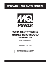
MAJOR COMPONENTS
220
220
U
V
W
O
GND
Denyo
OFF
W
U
V
OFF
W-U
V-W
U-V
DECREASE
INCREASE
PSI
OIL PRESS
0
25
50
75
100
°F
WATER TEMP
100
140
180
220
260
VOLTS
BATTERY
6
12
18
24
30
FUEL
E
½
F
RPMX10
SPEED
0
120
150
180
210
60
Engine Started
Shutdown
Pre-Alarm
Series 800 Controller
Alarm
Acknowledge
Screen
Change
Program/
Exit
Option
ECU
1
2
3
4
5 6
7
8
11
9
10
X
Y
Z
O
U
U
1
2
V
V
2
1
W
W
2
1
1
2
3
4
5
6
12
Table 5. Generator Major Components
ITEM NO. DESCRIPTION
1 Muffler Assembly
2 Enclosure Assembly
3 Generator Assembly
4 Battery Assembly
5 Engine Assembly
6 Fuel Tank Assembly
7 Output Terminal Assembly
8 Circuit Breaker Assembly
9 Auto Start/Stop Controller Assembly
10 Gauge Unit Assembly
11 Operating Panel Assembly
12 Voltage Change-Over Board
Figure 4. Major Components

PAGE 20 — DCA220SSJU4F 60 HZ GENERATOR • OPERATION MANUAL — REV. #4 (01/24/18)
ENGINE CONTROLLER UNIT (ECU 835)
Figure 5. Engine Control Unit (ECU)
PSI
OIL PRESS
0
25
50
75
100
°F
WATER TEMP
100
140
180
220
260
VOLTS
BATTERY
6
12
18
24
30
°F
FUEL
E
½
F
RPMX10
SPEED
0
120
150
180
210
60
Series 800 Controller
ECU
Engine Started
Shutdown
Pre-Alarm
Alarm
Acknowledge
Screen
Change
Program
Exit
Option
OFF
U-V
W-U
V-W
OFF
V
W
U
INCREASE DECREASE
Series 800 Controller
ECU
Engine Started
Shutdown
Pre-Alarm
Alarm
Acknowledge
Screen
Change
Program
Exit
Option
A
B
C
D
E F
G
H
1
The definitions below describe the controls and functions
of the Engine Control Unit (Figure 5).
1. ECU 835 Controller — This auto start/stop
controller displays the parameters and the diagnostic
troubleshooting messages of the engine, and controls
DPF regeneration.
A. ECU Display Screen — Engine fault diagnostic
messages are shown on this LCD display. screen
B. Engine Started Lamp — This lamp when lit
indicates engine is operating normally.
C. Engine Shutdown Lamp — When an engine
failure has occured this lamp will blink. Indicating
the engine has been shutdown. The diagnostic
fault message will be displayed on the LCD screen.
D. Pre Alarm Lamp — When an engine failure has
occured this lamp will blink. Indicating a pre-fault
engine condition and the possibility of engine
shutdown.The diagnostic fault message will be
displayed on the LCD screen.
E. Alarm Acknowledge Button — When the engine
experiences a fault, the "Pre Alarm Lamp" or the
"Shutdown Lamp" will start blinking. Pushing this
button will confirm the fault message and the
blinking lamp will change to a solid lamp display.
The fault message will be displayed on the screen.
When multiple engine faults occur, the lamp will
continue blnking until all fault messages are
confirmed. The blinking lamp will change to a solid
lamp display all current confirmed fault messages
will scrool across the screen.
F. Screen Change Button — When this button is
pushed during operation, the screen will cycle
through each parameter screen.
G. Option Button — This button is not active. Do
not use.
H. Program/Exit Button — Pushing this button
allows the DPF Force Regen and diagnostic code
to be confirmed.
/