Important Safety Instructions
Do not use this apparatus near water.
Do not use this apparatus near water.
Clean only with dry cloth.
Clean only with dry cloth.
Do not block any ventilation openings. Install in
Do not block any ventilation openings. Install in
accordance with the manufacturer’s instructions.
accordance with the manufacturer’s instructions.
Do not install near any heat sources such as radiators,
Do not install near any heat sources such as radiators,
heat registers, stoves, or other apparatus (including
heat registers, stoves, or other apparatus (including
amplifiers) that produce heat.
amplifiers) that produce heat.
Do not defeat the safety purpose of the polarized or
Do not defeat the safety purpose of the polarized or
grounding type plug. A polarized plug has two blades
grounding type plug. A polarized plug has two blades
with one wider than the other. A grounding type plug
with one wider than the other. A grounding type plug
has two blades and a third grounding prong. The wide
has two blades and a third grounding prong. The wide
blade or the third prong are provided for your safety. If
blade or the third prong are provided for your safety. If
the provided plug does not fit into your outlet, consult
the provided plug does not fit into your outlet, consult
an electrician for replacement of the obsolete outlet.
an electrician for replacement of the obsolete outlet.
Protect the power cord from being walked on or
Protect the power cord from being walked on or
pinched particularly at plugs, convenience receptacles,
pinched particularly at plugs, convenience receptacles,
and the point where they exit from the apparatus.
and the point where they exit from the apparatus.
Only use attachments / accessories specified by the
Only use attachments / accessories specified by the
Use only with the cart, stand, tripod, bracket, or
Use only with the cart, stand, tripod, bracket, or
table specified by the manufacturer, or sold with the
table specified by the manufacturer, or sold with the
apparatus. When a cart is used, use
apparatus. When a cart is used, use
caution when moving the cart /
caution when moving the cart /
apparatus combination to avoid injury
apparatus combination to avoid injury
Unplug this apparatus during lightning storms or when
Unplug this apparatus during lightning storms or when
unused for long periods of time.
unused for long periods of time.
Refer all servicing to qualified service personnel.
Refer all servicing to qualified service personnel.
Servicing is required when the apparatus has been
Servicing is required when the apparatus has been
damaged in any way, such as power-supply cord or
damaged in any way, such as power-supply cord or
plug is damaged, liquid has been spilled or objects
plug is damaged, liquid has been spilled or objects
have fallen into the apparatus, the apparatus has been
have fallen into the apparatus, the apparatus has been
exposed to rain or moisture, does not operate
exposed to rain or moisture, does not operate
normally, or has been dropped.
normally, or has been dropped.
Note to the CATV system installer:
Note to the CATV system installer:
This reminder is provided to call the CATV system installer’s
This reminder is provided to call the CATV system installer’s
attention to Article 820-40 of the NEC that provides
attention to Article 820-40 of the NEC that provides
guidelines for proper grounding and, in particular, specifies
guidelines for proper grounding and, in particular, specifies
that the cable ground shall be connected to the grounding
that the cable ground shall be connected to the grounding
system of the building, as close to the point of cable entry
system of the building, as close to the point of cable entry
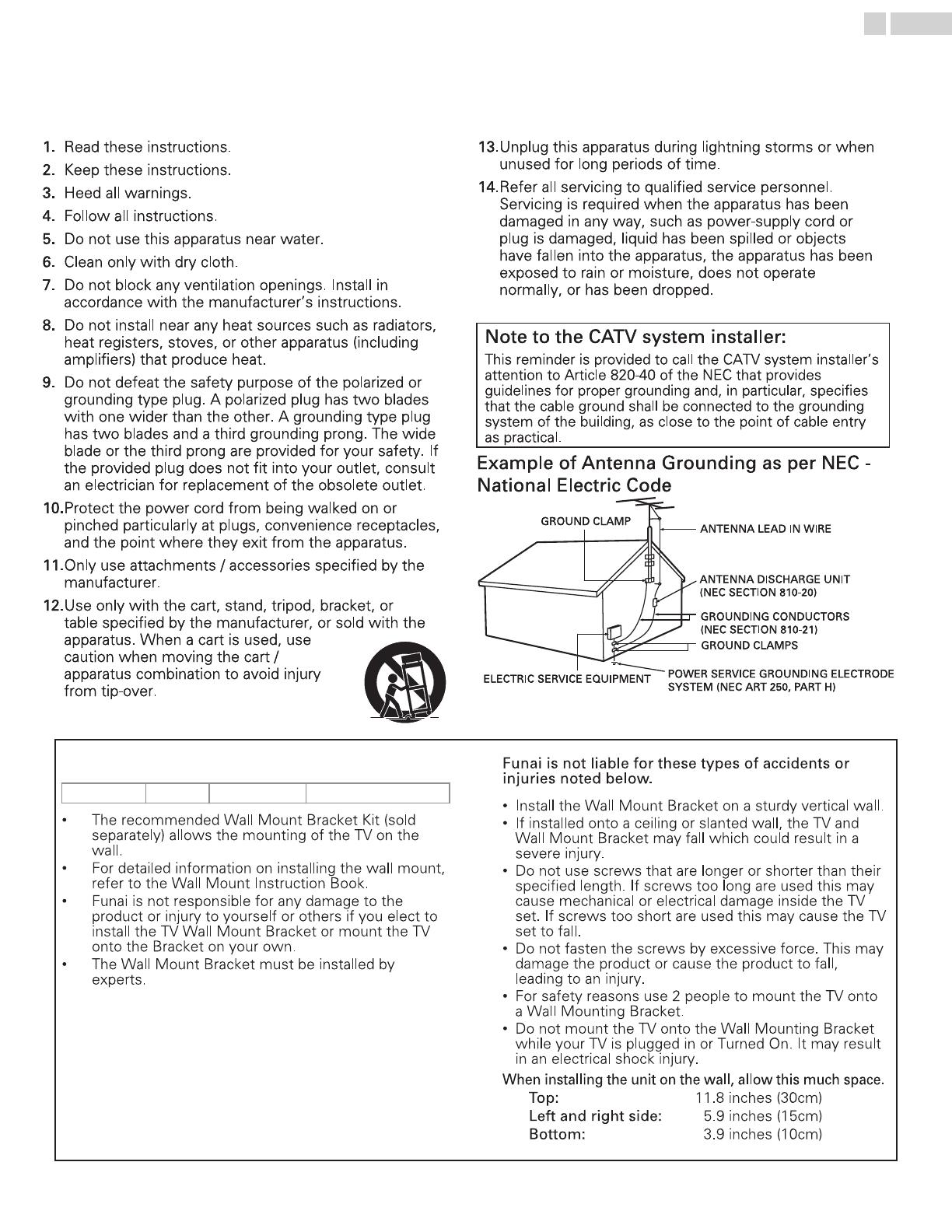
Example of Antenna Grounding as per NEC -
Example of Antenna Grounding as per NEC -
ELECTRIC SERVICE EQUIPMENT
ELECTRIC SERVICE EQUIPMENT
POWER SERVICE GROUNDING ELECTRODE
POWER SERVICE GROUNDING ELECTRODE
SYSTEM (NEC ART 250, PART H)
SYSTEM (NEC ART 250, PART H)
Do not use this apparatus near water.
Do not use this apparatus near water.
Clean only with dry cloth.
Clean only with dry cloth.
Do not block any ventilation openings. Install in
Do not block any ventilation openings. Install in
accordance with the manufacturer’s instructions.
accordance with the manufacturer’s instructions.
Do not install near any heat sources such as radiators,
Do not install near any heat sources such as radiators,
heat registers, stoves, or other apparatus (including
heat registers, stoves, or other apparatus (including
amplifiers) that produce heat.
amplifiers) that produce heat.
Do not defeat the safety purpose of the polarized or
Do not defeat the safety purpose of the polarized or
grounding type plug. A polarized plug has two blades
grounding type plug. A polarized plug has two blades
with one wider than the other. A grounding type plug
with one wider than the other. A grounding type plug
has two blades and a third grounding prong. The wide
has two blades and a third grounding prong. The wide
blade or the third prong are provided for your safety. If
blade or the third prong are provided for your safety. If
the provided plug does not fit into your outlet, consult
the provided plug does not fit into your outlet, consult
an electrician for replacement of the obsolete outlet.
an electrician for replacement of the obsolete outlet.
Protect the power cord from being walked on or
Protect the power cord from being walked on or
pinched particularly at plugs, convenience receptacles,
pinched particularly at plugs, convenience receptacles,
and the point where they exit from the apparatus.
and the point where they exit from the apparatus.
Only use attachments / accessories specified by the
Only use attachments / accessories specified by the
Use only with the cart, stand, tripod, bracket, or
Use only with the cart, stand, tripod, bracket, or
table specified by the manufacturer, or sold with the
table specified by the manufacturer, or sold with the
apparatus. When a cart is used, use
apparatus. When a cart is used, use
caution when moving the cart /
caution when moving the cart /
apparatus combination to avoid injury
apparatus combination to avoid injury
Unplug this apparatus during lightning storms or when
Unplug this apparatus during lightning storms or when
unused for long periods of time.
unused for long periods of time.
Refer all servicing to qualified service personnel.
Refer all servicing to qualified service personnel.
Servicing is required when the apparatus has been
Servicing is required when the apparatus has been
damaged in any way, such as power-supply cord or
damaged in any way, such as power-supply cord or
plug is damaged, liquid has been spilled or objects
plug is damaged, liquid has been spilled or objects
have fallen into the apparatus, the apparatus has been
have fallen into the apparatus, the apparatus has been
exposed to rain or moisture, does not operate
exposed to rain or moisture, does not operate
normally, or has been dropped.
normally, or has been dropped.
Note to the CATV system installer:
Note to the CATV system installer:
This reminder is provided to call the CATV system installer’s
This reminder is provided to call the CATV system installer’s
attention to Article 820-40 of the NEC that provides
attention to Article 820-40 of the NEC that provides
guidelines for proper grounding and, in particular, specifies
guidelines for proper grounding and, in particular, specifies
that the cable ground shall be connected to the grounding
that the cable ground shall be connected to the grounding
system of the building, as close to the point of cable entry
system of the building, as close to the point of cable entry
Example of Antenna Grounding as per NEC -
Example of Antenna Grounding as per NEC -
ELECTRIC SERVICE EQUIPMENT
ELECTRIC SERVICE EQUIPMENT
POWER SERVICE GROUNDING ELECTRODE
POWER SERVICE GROUNDING ELECTRODE
SYSTEM (NEC ART 250, PART H)
SYSTEM (NEC ART 250, PART H)
Wall Mount Bracket Kit
Brand Model # Screw dimension
FW55D25F
SANUS PLA50B M6 x 0.472" (12mm)
• The recommended Wall Mount Bracket Kit (sold
separately) allows the mounting of the TV on the
wall.
• For detailed information on installing the wall mount,
refer to the Wall Mount Instruction Book.
• Funai is not responsible for any damage to the
product or injury to yourself or others if you elect to
install the TV Wall Mount Bracket or mount the TV
onto the Bracket on your own.
• The Wall Mount Bracket must be installed by
experts.
Funai is not liable for these types of accidents or
injuries noted below.
• Install the Wall Mount Bracket on a sturdy vertical wall.
• If installed onto a ceiling or slanted wall, the TV and
Wall Mount Bracket may fall which could result in a
severe injury.
• Do not use screws that are longer or shorter than their
specified length. If screws too long are used this may
cause mechanical or electrical damage inside the TV
set. If screws too short are used this may cause the TV
set to fall.
• Do not fasten the screws by excessive force. This may
damage the product or cause the product to fall,
leading to an injury.
• For safety reasons use 2 people to mount the TV onto
a Wall Mounting Bracket.
• Do not mount the TV onto the Wall Mounting Bracket
while your TV is plugged in or Turned On. It may result
in an electrical shock injury.
When installing the unit on the wall, allow this much space.
Top: 11.8 inches (30cm)
Left and right side: 5.9 inches (15cm)
Bottom: 3.9 inches (10cm)
4 .English


