PS Engineering PM1000II Installation guide
- Type
- Installation guide
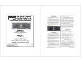
PS Engineering PM1000II is a 4-place intercom system with individual volume and squelch controls for the pilot and copilot. It features an automatic fail-safe interconnect to the aircraft radio, a music input, and a "crew" mode for uninterrupted aircraft radio communications for the pilot.
PS Engineering PM1000II is a 4-place intercom system with individual volume and squelch controls for the pilot and copilot. It features an automatic fail-safe interconnect to the aircraft radio, a music input, and a "crew" mode for uninterrupted aircraft radio communications for the pilot.


-
 1
1
-
 2
2
-
 3
3
-
 4
4
-
 5
5
-
 6
6
-
 7
7
-
 8
8
-
 9
9


PS Engineering PM1000II Installation guide
- Type
- Installation guide
PS Engineering PM1000II is a 4-place intercom system with individual volume and squelch controls for the pilot and copilot. It features an automatic fail-safe interconnect to the aircraft radio, a music input, and a "crew" mode for uninterrupted aircraft radio communications for the pilot.
Ask a question and I''ll find the answer in the document
Finding information in a document is now easier with AI
Related papers
-
Engineering Incorporated PAC45 Pilot's Manual
-
PS Engineering PSA210 Installation guide
-
PS Engineering Tactical Radio Adapter Installation guide
-
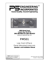
 Engineering Incorporated PM501 Operator's & Installation Manual
-
-
PS Engineering PM3000 Installation guide
-
PS Engineering PMA7000BT System Installation And Operation Manual
-
PS Engineering PRD60 Installation guide
-
-
PS Engineering PMA7000B Installation guide

Other documents
-
 Kenu AF1-KK-NA Datasheet
-
Clear-Com ICS-22 Panels User manual
-
Rugged Radios RRP6100 User manual
-
 Cirrus SR22 Maintenance Manual
-
Sigtronics UT-12D Installation And Operating Instructions Manual
-
Electronics International SC-5 Installation guide
-
 Audio Authority 670-530 User manual
-
Telex M-20 User manual
-
 Engineering Incorporated PM501 Operator And Installation Manual
-
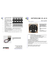 Alphatec IC - A13 User manual


