Page is loading ...

FS-53
L
AT
/R
OW
A
SSEMBLY
M
ANUAL
Model: FS53
Rev: 030620

2
Frank Trulaske began TRUE Fitness® over thirty-five year ago with the simple philosophy of
delivering superior fitness products, service, and support. Today, TRUE is the global leader in
premium fitness equipment for the commercial and residential markets. Our goal is to be the
leader in technology, innovation, performance, safety and style. TRUE has received many
awards for its product over the years and remains the benchmark for the industry. Fitness
facilities and consumers invest in TRUE products for their durable commercial platforms used
in all its products, both commercial and residential alike.
The proud manufacturing tradition of quality and the culture of innovation at TRUE have
given rise to a full line of extraordinary cardio and strength equipment. As a result, people all
over the world are benefiting from the TRUE experience. Innovation across the full product line
has made TRUE successful and is a trademark of the TRUE heritage. TRUE’s patented Heart
Rate Control technology is just one of the remarkable ways we deliver simple and superior
performance every user can enjoy, and most importantly, use to achieve personal health and
fitness goals.
At the heart of our success is the relentless and systematic life testing of both our products and
their components. We have dedicated employees who understand our philosophy is to deliver
the best products in the world.
Our goal is to deliver the world’s best premium equipment for our customers’ health and fitness
solutions.
A MESSAGE TO OUR CUSTOMERS

3
S
AFETY
...................................................................................................................... 4
G
ENERAL
C
ARE
AND
M
AINTENANCE
........................................................................... 7
D
IMENSIONS
AND
W
EIGHT
........................................................................................... 8
P
REPARATION
............................................................................................................. 9
B
OX
1 C
ARTON
C
ONTENTS
............................................................................................ 10
B
OX
2 C
ARTON
C
ONTENTS
............................................................................................ 11
I
NSTALLATION
& A
SSEMBLY
S
TEP
1: A
SSEMBLE
THE
M
AIN
F
RAME
...................................................................... 12
S
TEP
2: A
SSEMBLE
W
EIGHT
S
TACK
& L
AT
TUBE
...................................................... 14
S
TEP
3:A
SSEMBLE
F
RONT
S
HROUD
,R
OW
T
UBE
, F
OOT
F
RAME
.................................. 16
S
TEP
4: A
SSEMBLE
R
OW
C
ABLE
& R
OW
T
UBE
S
UPPORT
......................................... 19
S
TEP
5: I
NSTALL
L
AT
B
AR
& R
OW
H
ANDLE
............................................................. 21
S
TEP
6: I
NSTALL
R
EAR
S
HROUD
& T
OP
C
AP
............................................................ 22
S
TEP
7 I
NSTALL
THE
W
EIGHT
S
TACK
L
ABEL
............................................................. 24
B
OLTING
THE
M
ACHINE
TO
THE
F
LOOR
............................................................................ 25
C
ABLE
R
EPLACEMENT
& C
ABLE
R
OUTING
D
IAGRAM
........................................................ 26
M
ACHINE
L
ABELS
........................................................................................................ 28
S
ERVICE
..................................................................................................................... 29
W
ARRANTY
................................................................................................................. 30
TABLE OF CONTENTS

4
F
ACILITY
AND
U
SER
S
AFETY
P
RECAUTIONS
1. Review and understand all of the warning labels affixed to this machine and on the facility
safety sign.
2. Be certain that the machine operation is understood before it is used. Refer to the
instructional Procedure Label affixed to the machine.
3. Make sure all users are properly trained on how to use this equipment. If this machine is
being used in a commercial setting, end users may not have access to this Owners Manual. It
is the responsibility of the facility to instruct users as to the proper usage of the equipment as
well as making them aware of potential hazards. Maximum user weight is 300 lbs (136 kg).
4. Use each machine only for the intended exercise. Do not allow anyone to invent exercises not
included on the Instructional Procedure Label or the Intended Use Label.
5. Do not modify the machine.
6. This equipment meets industry safety standards for stability when used for the intended
exercise. Do not allow straps, resistance bands or other means to be attached to the
framework of this machine to perform stretching or body weight exercises. This can result in
machine instability and lead to serious crushing injuries.
7. Keep children away from this equipment. Adults should closely supervise use by teenagers.
8. It is recommended that users receive a thorough medical exam before commencing an
exercise program. All medical issues should be reviewed to ensure that weight training will
not aggravate pre-existing medical conditions.
9. If the machine appears damaged or inoperable, contact a facility staff member to place an
“OUT OF ORDER, DO NOT USE” sign on the machine until it is repaired. Only use TRUE
supplied replacement components to service this machine.
10. Instruct users not to wear loose or dangling clothes or have headphone wires hanging
when using this equipment.
11. Do not attempt to free any jammed assemblies by yourself as this may cause injury.
12. On Plate Loaded and Free Weight machines:
12a. Use of spotter(s). Instruct users to seek the advice of the facility staff as to the
appropriate use of spotters when lifting. More then one spotter may be required
depending upon the amount of weight being lifted.
12b. Instruct users to load weight plates evenly and carefully (one side and then the other)
to avoid tipping equipment and crushing injuries.
12c. If the machine is equipped with safety stops or catches, inspect them and verify their
proper operation before use and make sure they are securely in place before using or
exiting the machine. Be certain members are instructed on how to operate and adjust
all safety mechanisms.
SAFETY

5
12d. This equipment is designed for standard olympic size weight plates with a 50mm bore
(1.9”).
12e. Do not exceed the maximum weight capacity of the machine. Maximum plate size is
45 lbs. (25 kg.).
13. On Selectorized and Cable equipped machines:
13a. Do not allow users to perform any exercise by holding the end of the cable and/or the
cable end fitting. Use only appropriate handles or attachments properly connected to
the cable end.
13b. Do not high-pin or double-pin the weight stack. Do not allow the machine to be used if
the top plate or weight stack is pinned in a raised position. Use an assistant and
carefully return the machine to the proper position with the cap plate resting on the top
weight. Inspect the entire length of the cable to ensure that it is properly seated in all
of the pulley grooves.
13c. Do not allow the use of weight plates or dumbbells to be used as a means to add
additional weight to the weight stacks. Use only the TRUE adder weight system
specifically designed for the machine.
I
NSTALLATION
S
AFETY
P
RECAUTIONS
1. Read this Installation Manual entirely before assembling this equipment.
2. Verify that there is adequate space surrounding this piece of equipment for safe access and
operation. Installation must meet ADA requirements for accessibility.
3. Install this piece of equipment on a solid level surface that does not deviate more then 1/8”
over a 10’ distance (or as defined and required by local building and architectural codes.
4. TRUE strongly recommends that all equipment be anchored to the floor to prevent movement
and increase stability.
• Due to the wide variation of flooring on which the unit can be installed, contact a
qualified contractor to determine an appropriate fastening system for your floor.
• Use 3/8” diameter hardware (10 mm) to anchor the machine. Anchors should have a
minimum pull out force of 220 lbs (110 kgs) for each position.
• When attaching the machine to the floor, if there is a gap between the machine foot
and the floor, do not use the anchor to remove the gap as this can cause the
machine frame to deform. Instead, place a shim between the bottom of the foot and
the floor, then tighten the anchor.
• Anchoring holes are provided on the feet of the frame. All anchoring locations must
be used when anchoring the equipment to the floor.
5. DO NOT install any fitness equipment near a pool, hot tub or other damp locations. Corrosion
caused by installation in these locations can lead to premature failure of components.
6. Be sure all hardware is tight before using this machine.
SAFETY

6
M
AINTENANCE
S
AFETY
P
RECAUTIONS
1. Refer to Maintenance Schedule label on the machine as well as this manual for when to
perform maintenance.
2. Check the function of your machine DAILY by verifying the following:
• Inspect cables and end fittings for any signs of wear. Replace if worn, frayed or
damaged with original TRUE replacement components.
• Verify that all adjustments are possible and carried out with ease. Make sure that
each adjustment pin inserts completely into each position without binding.
• Verify that safety catches and stops are in proper working order and engaged.
• Verify that the exercise is performed smoothly, free of noise and/or binding.
• If equipped with a weight stack, verify that the proper weight selector pin is in place.
3. Check the function of your machine WEEKLY by verifying the following:
• Nuts, Bolts, and Fasteners: Check tightness weekly. If any hardware has become
loose, retighten and/or use Loctite
™
Threadlocker 242.
• Frames and Lifting Arms: Inspect weekly for integrity and function. Replace any
component at first signs of wear. Use only TRUE supplied components.
4. Replace any warning label at first sign of wear. Labels and the Facility Safety Sign may be
obtained from TRUE free of charge.
B
OLT
L
ENGTH
M
EASURING
G
UIDE
SAFETY
FLAT HEAD SCREW
BUTTON HEAD SCREW
HEX HEAD SCREW
SOCKET HEAD SCREW
1
23
4
5

7
IMPORTANT
Preventative maintenance is crucial to maintaining the function and safety of this equipment. Your
facility must establish written guidelines for preventative maintenance and keep written or online
records of the maintenance performed on these products. As a minimum, the items presented in
the SAFETY section of this document and the items that follow here, should be included in your
maintenance program.
1. Cables: Inspect end fittings daily for wear. Inspect the entire length of the cable weekly.
Replace cables at the first sign of wear and on an annual basis. If the cable tension has
been adjusted, be certain that the cable nut is tight.
2. Nuts, Bolts, and Fasteners: Check tightness weekly. If any hardware has become loose,
retighten and/or use Loctite
TM
brand Threadlocker 242. Be sure all hardware is tight
before using the machine.
3. Safety Catches: Inspect catches, stop rods and their associated fasteners weekly.
Tighten any loose hardware and replace any components at first signs of wear.
4. Frames: Sweat, disinfecting sprays and spills can lead to corrosion which may lead to
premature failure of components. Wipe all machines down with a damp cloth and dry
completely each day. This includes painted parts, chrome parts and upholstered pads.
5. Painted and chrome plated parts: Use Simple Green or similar cleaner for light dirt and
grime. Use Turtle Wax Polishing Compound or a good car polish to remove heavier dirt
and grease as well as for polishing. DO NOT use solvents, lacquer thinner, acetone or
finger nail polish remover. For scuffs and marks that are not removed by the above
methods use a soft scrub cleanser. Make sure all parts are dry upon completion.
6. Weight stack enclosures (shrouds): Wipe down with a damp cloth as needed.
7. Exercise instruction labels: Clean with soap and water as needed.
8. Guide rods: Wipe all dirt and dust from the guide rods before applying a light application
of Tri-Flow
TM
or other teflon spray lubricant. Spray the Tri-Flow
TM
on a rag and then wipe
the guide rods with the rag. DO NOT use oil lubricants such as WD-40. Caution: Tri-Flow
TM
will
stain carpet and clothing.
9. Bronze bushings: Check monthly for signs of wear and replace as needed.
10. Linear Bearing Shafts: Wipe any accumulation of dust or other contaminants from the
shafts on a weekly basis. Apply a thin layer of a Teflon® (PTFE) grease on a weekly basis.
TRUE recommends Magnalube® brand.
11. When replacing any component, use only TRUE supplied parts.
12. Please refer to the General Maintenance Manual (part number: AM-GMM) for other
important safety and maintenance information.
13. Be sure all hardware is tight before using the machine.
Retain these instructions for future reference.
If you have any questions, do not hesitate to contact your TRUE dealer or TRUE at (800) 883-8783
or service@truefitness.com.
GENERAL CARE AND MAINTENANCE

8
DIMENSIONS AND WEIGHT
[1199]
47-1/4”
[1936]
76-1/4”
[2126]
83-3/4”
W
EIGHT
S
TACK
C
ONFIGURATION
M
ACHINE
WEIGHT
A
PPROXIMATE
F
LOOR
L
OADING
170 lbs. 454 LBS [206 KG] 53 LBS/FT
2
[257 KG/M
2
]
250 lbs. 534 LBS [242 KG] 62 LBS/FT
2
[303 KG/M
2
]
M
ACHINE
W
EIGHT
AND
F
LOOR
L
OADING
“I
N
U
SE
” M
ACHINE
D
IMENSIONS
M
AXIMUM
U
SER
W
EIGHT
300LBS (136KG)

9
PREPARATION
R
EQUIRED
T
OOLS
Ratchet Wrench and Socket:
9/16”
Wrenches: 9/16”
(or an adjustable crescent wrench).
Rubber mallet.
Allen wrenches:
(included with the machine)
Measurement Guide:
SHCS - SOCKET HEAD CAP SCREW
FHCS - FLAT HEAD CAP SCREW
HHCS - HEX HEAD CAP SCREW
BHCS - BUTTON HEAD CAP SCREW
MEASURE BOLT
FROM HERE
12345
Use this table to measure bolts and set collar spacing.
Weight Plate Cartons
Depending upon your order, this machine can be assembled with either a 170 lb. or 250
lb. weight stack. For a 170 lb. weight stack, (4) cartons of 10 lb. plates are required. For a
250 lb. weight stack, (4) cartons of 15 lb. plates are required.
See below for weight stack options/requirements:
10 LB. Weight Plate Box
Part Number: B1602
Comprised of
(4)
x
10 lb. Weight Plates
15 LB. Weight Plate Box
Part Number: B1603
Comprised of
(4) x 15lb. Weight Plates
OR

10
BOX 1 CARTON CONTENTS
1
2
3
4
5
6
7
8
9
ITEM
P
ART
N
UMBER
D
ESCRIPTION
Q
TY
1 FS-CAP-000X TOP CAP 1
2 FS53-SHD-300X FRONT SHROUD 1
3 FS-SHD-350X REAR SHROUD 1
4 FS53-UPR-000X UPRIGHT 1
5 FS53-GRD-300X GUIDE ROD 2
6 FS53-PAD-100X SEAT PAD 1
7 FS-BKT-000 GUIDE ROD BRACKET 2
8 FS-PAD-400X ROLLER PAD, SHORT 2
9 FS-BKT-001 TOP CAP BRACKET 2
10 FS-WSB-000 WEIGHT STACK BASE 2
10

11
BOX 2 CARTON CONTENTS
ITEM
P
ART
N
UMBER
D
ESCRIPTION
Q
TY
1 FS53-MFR-100X LAT TUBE 1
2 FS53-MFR-200X ROW TUBE 1
3 FS53-MFR-300X ROW TUBE SUPPORT 1
4 FS53-MFR-400X FLOATING PULLEY SET 1
5 FS53-SFR-100X FOOT FRAME 1
6 FS53-SFR-200X FOOT PLATE 2
7 FS53-SFR-300X SEAT FRAME 1
8 FS53-SFR-400X THIGH FRAME 1
9 FS-BAR-100X LAT BAR 1
10 FS-BAR-200X ROW HANDLE 1
11 FS53-CBL-100X LAT CABLE 1
12 FS53-CBL-200X ROW CABLE 1
13 FS-SBR-000X SELECTOR BAR 1
14 FS53-HWR-000X HARDWARE BOX 1
15 FS53-FPL-002 FOOT PLATE BRACE 1
1
11
12
4
9
10
2
3
5
6
7
8
13
HARDWARE BOX
14
15

12
STEP 1: ASSEMBLE THE MAIN FRAME
1. Assemble frame components as shown.
2.
Lo
osely assemble ALL hardware shown
in this step
.
3
.
Aft
er aligning all component edges an
d
su
rfaces, tighten the hardware.
4. Install the rubber feet
10,13,12,9,7,8,5,8
X 2
3
5
ITEM
P
ART
N
UMBER
D
ESCRIPTION
Q
TY
1 FS53-UPR-000X UPRIGHT FRAME 1
2 FS53-SFR-300X SEAT FRAME 1
3 FS53-SFR-400X THIGH FRME 1
4 FS53-PAD-100X SEAT PAD 1
5 FS-PAD-400X THIGH ROLLER PAD 2
6 S 550 FOOT, MOLDED 4
7 C-965 WASHER, FENDER, 3/8 2
8 FS53-SFR-001 ROLLER COVER, PLASTIC 4
9 C 955A COVER, BASE 7
10 C 955S COVER, SILVER PLASTIC 7
11 C 754C WASHER, FLAT, 3/8 5
12 C 749 WASHER, LOCK, 3/8 7
13 C 444 SCREW, HH, 3/8 X 3/4 2
14 C 445 SCREW, HH, 3/8 X 1 3
15 C 451 SCREW, HH, 3/8 X 2-3/4 2

13
STEP 1: ASSEMBLE THE MAIN FRAME
10,14,12,9,11
X 3
10,15,9,12,11
X 2
1
2
4
DETAIL A
DETAIL B
A
B

14
STEP 2: ASSEMBLE WEIGHT STACK & LAT TUBE
10,8,9 X 2
6
X 2
1
X 2
2
3
X 2
4
X 2
5
X 2
The Selector Pin should
be installed as shown.
C
DETAIL C
1. Assemble the Weight Stack,
Bumper, Weight Stack Support,
Top Plate/Selector Bar, Guide
Rods, Weight Stack 1” Washer,
and Collars as shown below.
2. Lock the guide rods as shown in
view DETAIL C.
3. Install the Lat Tube as shown in
view DETAIL D.
4. Align all component and tighten
all hardware.
ITEM
P
ART
N
UMBER
D
ESCRIPTION
Q
TY
1 FS-GRD-300X GUIDE ROD 2
2 FS-SBR-000X TOP PLATE/SELECTOR BAR 1
3 C 757A WASHER, WEIGHT STACK 1” 2
4 FS-BMP-001 BUMPER, WEIGHT STACK 2
5 FS-WSB-000 WEIGHT STACK SUPPORT 2
6 FS-BKT-000 GUIDE ROD BRACKET 2
7 FS53-MFR-100X LAT TUBE 1
8C 749 WASHER, LOCK 3/8 6
9 C 754C WASHER, FLAT, 3/8 6
10 C 445 SCREW, HH, 3/8 X 1 6
11 D 840 Collar, Clamping, 1” I.D. 2
12 FS-SPN-000X SELECTOR PIN 1

15
STEP 2: ASSEMBLE WEIGHT STACK & LAT TUBE
10,8,9
X 4
Set the distance between
the Collars and the tube as shown
1” distance from the bottom of the bolt to the
top of the bar as shown. Lock the nut after the
distance is set.
D
DETAIL D
1”
2 1/2”
Use tape measure

16
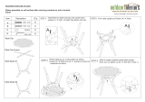
STEP 3:ASSEMBLE FRONT SHROUD,ROW TUBE, FOOT FRAME
1. Install the front Shroud first. Slide
the top portion of the shroud up to
the Lat Tube from the side, and
push the lower portion of the
shroud into the Upright.
2. Install the Row Tube between the
Lat Tube and the Seat Frame. The
end of the Lat Tube might have to
be lifted to insert the Row Tube and
align all bolt holes.
3. Install the Foot Frame as shown in
View DETAIL H.
3. DO NOT TIGHTEN THE HARDWARE
SHOW ON VIEW DETAIL F AND
DETAIL G.
(
'(7$,/(
10,8,7 X 6
There are six sets of bolt and washers to hold down
the Front Shroud. Three sets on the left side, and
three sets on the right side.
1
DETAIL E
E
ITEM
P
ART
N
UMBER
D
ESCRIPTION
Q
TY
1 FS53-SHD-300X FRONT SHROUD 1
2 FS53-MFR-200X ROW TUBE 1
3 FS53-SFR-100X FOOT FRAME 1
4 FS53-SFR-200X FOOT PLATE 2
5 C 955A COVER 3/8, BASE 16
6 C 955S COVER, SILVER 16
7 C 745C WASHER, FLAT, 3/8 18
8C 749 WASHER, LOCK, 3/8 14
9 C 766A NUT, JAM, 3/8 6
10 C 445 SCREW, HH, 3/8 X 1” 6
11 C 449 SCREW, HH, 3/8 X 2-1/4” 4
12 C 451 SCREW, HH, 3/8 X 2-3/4” 2
13 C 455 SCREW, HH, 3/8 X 4” 4
14 FS53-FPL-002 FOOT PLATE BRACE 1

17
STEP 3:CONTINUED...
*
)
'(7$,/*
'(7$,/)
6,12,5,7 X 2
7,5,9,6 X 2
6,13,8,5,7
X 2
7,5,9,6
X 2
2
F
DETAIL F
DETAIL G
G

18
STEP 3 CONTINUED...
+
'(7$,/+
6,13,8,5,7
X 2
7,5,9,6
X 2
6,11,8,5
X 4
Slide Foot Plate on to the Foot Frame
and tighten all hardware.
H
DETAIL H
14

19
STEP 4:ASSEMBLE ROW CABLE & ROW TUBE SUPPORT
1. Install the Row Tube Support
below, then tighten all hardware in
previous steps.
2. Install the Row Cable as shown
next page.
ITEM
P
ART
N
UMBER
D
ESCRIPTION
Q
TY
1 FS53-MFR-300X ROW TUBE SUPPORT 1
2 FS53-ROL-001A ROW TUBE A, PVC 2
3 FS53-ROL-002A ROLL SHAFT A 2
4 B 900 PULLEY, 4.5” 2
5 FS-BSH-005 PULLEY BUSHING, 3/8 2
6C 749 WASHER, LOCK 3/8 6
7 C 745C WASHER, FLAT, 3/8 12
8 C 955A COVER, BASE 16
9 C 955S COVER, SILVER 16
10 C 443 SCREW, HH, 3/8 x 5/8 2
11 C 460 SCREW, HH, 3/8 x 5” 2
12 C 445 SCREW, HH, 3/8 x 1” 4
13 C 448 SCREW, HH, 3/8 x 1-3/4” 1
14 C 451 SCREW, HH, 3/8 x 2-3/4” 1
15 C 450 SCREW, HH, 3/8 x 2-1/2” 1
16 C 766A NUT, NYLOCK, JAM, 3/8 5
17 FS53-MFR-400X FLOATING PULLEY SET 1
18 FS53-CBL-200X ROW CABLE 1
-
.
'(7$,/-
'(7$,/.
9,11,8,7 X 2
9,16,8,7
X 2
9,10,6,8,7
X 2
J
K
DETAIL J
DETAIL K
1

20
STEP 4:ASSEMBLE ROW CABLE & ROW TUBE SUPPORT
$
%
'(7$,/$
'(7$,/%
9,16,8,7
9,13,8,7
17
4
9,12,8,6
X 2
9,16,8,7,5
9,16,8,7
9,12,8,6
X 2
3
X 2
2
X 2
4
9,14,8,7,5
9,15,8,7
18
DETAIL M
M
N
DETAIL N
1”
Adjust stop to remove
cable slack.
/