Boss Audio Systems 606C User manual
- Category
- Car media receivers
- Type
- User manual


2
CONTENTS
Installation...................................................................................................................3
DIN Front-Mount (Method A)........................................................................................3
Installing the unit ...................................................................................................3
Removing the unit..................................................................................................4
DIN Rear-Mount (Method B).........................................................................................5
Using the Detachable Front Panel ............................................................................6
Wiring Connection......................................................................................................7
Operation ....................................................................................................................8
General Operation .................................................................................................9
Radio Operation ..................................................................................................10
CD Operation.......................................................................................................10
Disc Notes ...........................................................................................................11
Specification .............................................................................................................12
Trouble shooting.......................................................................................................13

3
INSTALLATION
Notes:
• Choose the mounting location where
the unit will not interfere with the
normal driving function of the driver.
• Before finally installing the unit,
connect the wiring temporarily and
make sure it is all connected up
properly and the unit and the system
work properly.
• Use only the parts included with the
unit to ensure proper installation.
The use of unauthorized parts can
cause malfunctions.
• Consult with your nearest dealer if
installation requires the drilling of holes
or other modifications of the vehicle.
• If installation angle exceeds 30˚ from
horizontal, the unit might not give its
optimum performance.
• Avoid installing the unit where it would
be subject to high temperature, such
as from direct sunlight, or from hot air,
from the heater, or where it would be
subject to dust, dirt or excessive
vibration.
DIN FRONT/REAR-MOUNT
This unit can be properly installed either
from “Front” (conventional DIN Front-
mount) or “Rear” (DIN Rear-mount
installation, utilizing threaded screw holes
at the sides of the unit chassis).
For details, refer to the following
illustrated installation methods.
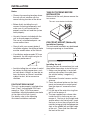
TAKE OUT SCREWS BEFORE
INSTALLATION
Before install the unit, please remove the
two screws.
DIN FRONT-MOUNT (Method A)
Installation Opening
This unit can be installed in any dashboard
having an opening as show below:
Installing the unit
Be sure you test all connections first, and
then follow these steps to install the unit.
1. Make sure the ignition is turned off,
and then disconnect the cable from
the vehicle battery's negative (-)
terminal.
2. Disconnect the wire harness and the
antenna.
3. Press the release button on the front
panel and remove the control panel
(see the steps of “remove the front
panel”).
4. Lift the top of the outer trim ring then
pull it out to remove it.
5. The two supplied keys release tabs
inside the unit's sleeve so you can
remove it. One key is for the right side
and the other is for the left side. Insert
the keys as far as they will go (with the
notches facing up) into the appropriate
slots at the middle left and right sides
of the unit. Then slide the sleeve off
the back of the unit.
30˚
182 mm
53 mm
Take out screw before installation

Note: to install the short threading terminal
of the mounting bolt to the back of the
unit and the other long threading terminal
to the dashboard.
10. Reconnect the cable to the vehicle
battery's negative (-) terminal. Then
replace the outer trim ring and install
the unit's front panel. (see the steps
of “install the front panel”).
Removing the unit
1. Make sure the ignition is turned off,
then disconnect the cable from the
vehicle battery's negative (-) terminal.
2. Remove the metal strap attached the
back of the unit (if attached).
3. Press the release button to remove the
front panel.
4. Lift the top of the outer trim ring then
pull it out to remove it.
5. Insert both of the supplied keys into
the slots at the middle left and right
sides of the unit, then pull the unit out
of the dashboard.
4
INSTALLATION
6. Mount the sleeve by inserting the sleeve
into the opening of the dashboard and
bend open the tabs located around the
sleeve with a screwdriver. Not all tabs
will be able to make contact, so
examine which ones will be most
effective. Bending open the
appropriate tabs behind the dashboard
to secure the sleeve in place.
7. Reconnect the wire harness and the
antenna and be careful not to pinch
any wires or cables.
8. Slide the unit into the sleeve until it
locks into place.
9. To further secure the unit, use the
supplied metal strap to secure the back
of the unit in place. Use the supplied
hardware (Hex Nut (M5mm) and Spring
Washer) to attach one end of the strap
to the mounting bolt on the back of
the unit. If necessary, bend the metal
strap to fit your vehicle's mounting
area. Then use the supplied hardware
(Tapping Screw (5x25mm) and Plain
Washer) to attach the other end of
metal strap to a solid metal part of the
vehicle under the dashboard. This strap
also helps ensure proper electrical
grounding of the unit.
Front Panel
Outer Trim Ring
L Key
Sleeve
R Key
Sleeve
Dashboard
Screwdriver
Tabs
Spring Washer
Tapping Screw
Plain Washer
Hex Nut
Metal Strap
Mounting Bolt

5
DIN REAR-MOUNT (Method B)
If your vehicle is a Nissan, Toyota, follow
these mounting instructions. Use the
screw holes marked T (Toyota), N (Nissan)
located on both sides of the unit to fasten
the unit to the factory radio mounting
brackets supplied with your vehicle.
To fasten the unit to the factory radio
mounting brackets.
1. Use a screwdriver to loose the hook's
screws on the front left and right sides
of the unit and remove the hooks.
2. Align the screw holes on the bracket
with the screw holes on the unit, and
then tighten the screws (5x5mm) on
each side.
Note: the outer trim ring, sleeve and the
metal strap are not used for method B
installation.
INSTALLATION
Dashboard or
Console
Side view showing
Screw Holes marked
T, N
Factory Radio
Mounting
Bracket
Hook
Screw
Screw
Hook

Precautions when Handling
1. Do not drop the front panel.
2. Do not put pressure on the display or
control buttons when removing or
installing the front panel.
3. Do not touch the contacts on the front
panel or on the main unit body. It may
result in poor electrical contact.
4. If any dirt or foreign substances
adhered on the contacts, they can be
removed with a clean and dry cloth.
5. Do not expose the front panel to high
temperatures or direct sunlight in
anywhere.
6. Keep away any volatile agents (e.g.
benzene, thinner, or insecticides) from
touching the surface of the front
panel.
7. Do not attempt to disassemble the
front panel.
6
USING THE DETACHABLE FRONT PANEL
REMOVE THE FRONT PANEL
1. Press the REL button on the front
panel and pull off the front panel.
2. Keep front panel into the case.
INSTALL THE FRONT PANEL
To install the front panel, insert the panel
into the housing and make sure the panel
is properly installed. Otherwise,
abnormality occurs on the display or some
keys will not function properly.
Release Button
Front Panel
Protective Case
Front Panel

7
WIRING CONNECTION
FRONT Lch
SPEAKER
GREEN
GREEN/BLACK
Constant 12
volts
MAIN UNIT
Rch RED
Lch WHITE
AUX IN CABLE
IGNITION
SWITCH (ACC+)
POWER
ANTENNA
RED
GROUND (B–)
YELLOW
BLACK
FUSE
BLUE
REAR RCA CABLE
(BLACK)
ANTENNA CONNECTOR
(GREY)
Rch RED
Lch WHITE
WHITE
WHITE/BLACK
REAR Lch
SPEAKER
FUSE
VIOLET
VIOLET/BLACK
GREY
GREY/BLACK
FRONT Rch
SPEAKER
REAR Rch
SPEAKER
FRONT RCA CABLE
(BROWN)
Rch RED
Lch WHITE

8
OPERATION
LOCATION OF KEYS
10
14 16 2 11
22
20 1 3 1912 13 5 17 4 9 6
18721 8 15

9
OPERATION
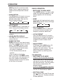
GENERAL OPERATION
• ON/OFF
Switch on the unit by pressing any
button (except REL button (6) and
button (4)). When system is on, press
POWER button (1) to turn off the unit.
• FACEPLATE RELEASE
Press REL button (6) to detach the
removable faceplate.
• LOUDNESS
For the unit with two bands only:
Press and hold BND/LOU button (8)
for several seconds to show the
loudness state. And shortly press it
again to turn on/off the subwoofer
output. In CD mode or AUX mode,
press BND /LOU button (8) shortly to
show the loudness state. And shortly
press it again to turn on/off the bass
output.
• SET THE CLOCK
Press DSP button (9) shortly to switch
display mode according to display
priority set mode.
Press and hold DSP button (9) for
several seconds until the clock is
shown on the display and flashes, then
press VOL+/- button (20)(21) to change
hours or the minutes.
• SELECT AUDIO MODE
Press SEL/MENU (3) shortly to change
audio mode through volume, bass,
treble, balance, and fader modes.
Press the VOL+/- button (20)(21) to
adjust the selected mode. When the
currently displayed function has not
been adjusted for several seconds, the
mode shall return to volume position
and display will return to normal radio,
CD or AUX display.
• MENU SELECTION FUNCTION
Hold press SEL/MENU (3) for several
seconds and you will enter the menu
functions then press the SEL/MENU
button to select the different modes.
Press the VOL+/- (20)(21) to select
your setting.
BEEP ON/OFF
- When the beep is on. It will beep with
every button you press.
- When the beep is turned off. It will
not beep when you push a button.
Program power on volume level
In this mode, you can set the desired
volume level when the unit turns on.
CLOCK ON/OFF while power off
In this mode, you can select if the clock
is to be displayed while power off.
NO PRI/CLOCK/FREQ priority
- When select No Priority:
When the frequency appears on the
unit, pressing DSP button (9) will
display clock and it will not return to
frequency display until DSP button
(9) pressed again. When the clock
appears on the unit, pressing DSP
button (9) will display frequency
information.
- When select Clock Priority:
The clock will appear on the unit all
the time. Pressing DSP button (9)
while in Clock Priority will temporarily
display selected station frequency (in
RADIO mode) or track number (in CD
mode) and then returns to clock
display.
- When select Frequency Priority:
The frequency will appear on the unit
all the time. Pressing DSP button (9)
while in Frequency Priority will
temporarily display clock and then
returns to frequency display.
12hours/24hours
In this mode, you can set 24 hours
mode or 12 hours mode. When the
currently displayed function has not
been adjusted for several seconds, it
will exit menu set mode.
• MUTE
In radio and AUX mode, press
BEEP ON/OFF Program power on volume level
12hours/24hours CLOCK/FREQ priority
CLOCK ON/OFF while power off
Volume Bass Treble Balance Fader

(MUT) button (2) to mute the audio
output. Press it again to release this
mode and recover previous volume
level.
• EQUALIZATION
Press EQ button (10) shortly to turn on
equalization function and to select
desired audio mode. There are five
kinds of mode as below:
• SELECT MODE
Press MODE button (7) repeatedly to
select among the following sources:
If no CD is present, CD mode will be
skipped.
• LIQUID CRYSTAL DISPLAY
The LCD (19) can show the current
state of the unit.
• RESET FUNCTION
RESET button (22) must be activated
with either a ballpoint pen or thin metal
object. The RESET button is to be
activated for the following reasons:
- Initial installation of the unit when
all wiring is completed.
- All the function buttons do not
operate.
- Error symbol on the display.
Note: If you press the RESET button
(22), and the does not come back on,
then use a cotton swab soaked in
isopropyl alcohol to clean the socket
on the front of the panel.
10
OPERATION
RADIO OPERATION
• SWITCHING TO RADIO MODE
Press MODE button (7) to select radio
mode, the radio mode appears in the
display together with the memory
band.
• BAND
For the unit with two bands only, press
BND/LOU button (8) shortly to change
bands as below:
• SELECT STATION
Rotate TUNING knob (11) clockwise
or counter-clockwise to adjust the
frequency upward or downward.
• LOCAL/DISTANT
Press the LOC button (12) to select
between local setting for reception of
strong station and distant setting for
reception of weak stations when
tuning.
• MONO/STEREO
In FM band, press MON button (13)
shortly to select mono or stereo
reception for radio stations. You can
sometimes improve reception of
distant stations by selecting mono
operation.
CD OPERATION
• SWITCHING TO CD MODE
If there is no CD inserted in the driver:
Gently insert the CD with the printed
side up into the disc slot (5) until you
feel some resistance. The CD is drawn
into the driver automatically. CD
playback begins.
If a CD is already inserted in the driver:
Keep pressing MODE button (7) shortly
until the CD mode display appears.
• EJECTING A DISC
Press button (4) to stop CD play and
eject CD from slot. Receiver switches
to radio operation.
FLAT CLASS POP M ROCK M
TUNER CD AUX
FM AM

DISC NOTES:
A. Notes on discs:
1. Attempting to use nonstandard
shape discs (e.g. square, start, heart)
may damage the unit. Be sure to
use round shape CD discs only for
this unit.
2. Do not stick paper or tape etc., onto
the label side or the recording side
of any discs, as it may cause a
malfunction.
3. Dirt, dust, scratches and warping
discs will cause misoperation.
B. Notes on CD-Rs (recordable
CDs)/CD-RWs (rewritable CDs) (For
With CDRs/CD-RWs Operation
Version Only):
1.Be sure to use discs with following
marks only for the unit to play:
2.The unit cannot play a CD-R and
CD-RW that is not finalized.
(Please refer to the manual of your
CD-R/CD-RW recorder or CD-R/
CD-RW software for more information
on finalization process).
3.Depending on the recording status,
conditions of the disc and the
equipment used for the recording,
some CD-Rs/CD-RWs may not be
played on this unit. (See *1)
*1:To have more reliable play back,
please see following
recommendations:
a. Use CD-RWs with speed 1x to 4x
and write with speed 1x to 2x.
b.Use CD-Rs with speed 1x to 8x and
write with speed 1x to 2x.
c. Do not play a CD-RW which has
been written for more than 5 times.
11
OPERATION
• PAUSING CD
Press
button (2) shortly to pause CD
player. Press it shortly again to resume
playback.
• SELECTING TRACKS
Press T-UP button (17) or T-DN button
(18) to choose the following track or
the previous track. Track numbers
show on display.
Hold T-UP button (17) or T-DN button
(18) for several seconds to fast forward
or fast reverse. Release the button to
stop fast playing.
• REPEATING THE SAME TRACK
Press RPT button (15) to continuously
repeat playing the current track. Press
it again to release this mode.
• PREVIEWING ALL TRACKS
Press SCN button (14) to play first
several seconds of each track. Press
it again to stop intro and listen to track.
• PLAYING ALL TRACKS IN RANDOM
Press SHF button (16) to play all tracks
in random order. Press it again to
cancel the function.
Recordable Rewritable

12
SPECIFICATION
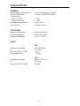
GENERAL
Power Supply Requirements : DC 12 Volts, Negative Ground
Chassis Dimensions : 178 (W) x 163 (D) x 50 (H)mm
Tone Controls
- Bass (at 100 Hz) : ± 7dB
- Treble (at 10 KHz) : ± 7 dB
Maximum Output Power : 40W x 4 (ch)
Current Drain : 15 Amps. (max.)
CD PLAYER
Signal to Noise Ratio : More than 55 dB
Channel Separation : More than 40 dB
Frequency Response : 50 Hz - 15 KHz
RADIO
FM
Frequency Coverage : 88 to 108 MHz
IF : 10.7 MHz
Sensitivity (S/N = 30 dB) : 15 μV
Stereo Separation : > 25 dB
AM
Frequency Coverage : 530 to 1710 KHz
IF : 450 KHz
Sensitivity (S/N = 20 dB) : 38 dBu

88-C2184-12
13
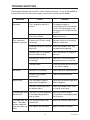
TROUBLE SHOOTING
Before going through the checklist, check wiring connection. If any of the problems
persist after check list has been made, consult your nearest service dealer.
Symptom Cause Solution
No power. The car ignition switch is If the power supply is
not on. connected to the car accessory
circuits, but the engine is not
moving, switch the ignition key
to “ACC”.
The fuse is blown. Replace the fuse.
Disc cannot be Presence of CD disc inside Remove the disc in the player,
loaded or ejected. the player. then put a new one.
Inserting the disc in reverse Insert the compact disc with
direction. the label facing upward.
Compact disc is extremely Clean the disc or try to play a
dirty or defective disc. new one.
Temperature inside the car Cool off or until the ambient
is too high. temperature return to normal.
Condensation. Leave the player off for an hour
or so, then try again.
No sound. Volume is in minimum.
Adjust volume to a desired level.
Wiring is not properly Check wiring connection.
connected.
Sound skips. The installation angle is Adjust the installation angle less
more than 30 degrees. than 30 degrees.
The disc is extremely dirty Clean the compact disc, then
or defective disc. try to play a new one.
The operation keys The built-in microcomputer Press the RESET button.
do not work. is not operating properly Front panel is not properly fixed
due to noise. into its place.
The radio does not The antenna cable is not Insert the antenna cable firmly.
work. The radio connected.
station automatic
selection does not The signals are too weak. Select a station manually.
work.

-
 1
1
-
 2
2
-
 3
3
-
 4
4
-
 5
5
-
 6
6
-
 7
7
-
 8
8
-
 9
9
-
 10
10
-
 11
11
-
 12
12
-
 13
13
-
 14
14


Boss Audio Systems 606C User manual
- Category
- Car media receivers
- Type
- User manual
Ask a question and I''ll find the answer in the document
Finding information in a document is now easier with AI
Related papers

Other documents
-
Insignia IN-CS102 User manual
-
Pyle PLCD85XMP Owner's manual
-
 PYLE Audio PLCD65WXMU User manual
-
Lanzar VBD1900MP Owner's manual
-
Pyle PYLE Hydra Series PLCD13MR Owner's manual
-
Lenco CS173DAB Owner's manual
-
Dynex IN-CS101 User manual
-
Radio Shack PLCD9MR User manual
-
-
