Page is loading ...

•
~
·
BRUEL
& KJJER
Nrerum-
Denmark
Consisting of:
Trouble Shooting:
SERVICE
INSTRUCTIONS
Impulse
Precision
Sound
Level
Meter
Checking Procedure
Power
Supply
Meter Circuit
Output
Amplifier
Input Amplifier
Weighting Network
Position
of
Components
Parts-List
Circuit Diagram
2204,1
2204,2
2204,3
2204.4
2204,5
2204,6
2204,7
2204,8
2204,9
2204
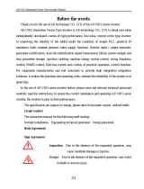
If
some sort
of
trouble occurs with this instrument then first check the D.
C.
working voltages from the Power Supply.
Then use the Checking Procedure with Block Diagram
in
order
to
localize a trouble
to
be
in
one certain circuit.
When a
fault has been found and remedied the voltages and adjustments which are influenced by the remedy must be
rechecked and the Checking Procedure can be used again
to
tell
if
all
basic functions of the instrument are fulfilled.
The tolerance stated
in
the
instructions can only be used as a guide for adjustment and control,
but
any deviations must
not
be
corrected without being sure
that
the tolerances of the instruments used for making the adjustment are so small as
to
have
no
influence on the measurements.
The instructions
in
this Manual are given purely as a guide to the service of equipment. Some faults,
as
f.inst. small
deviations
in
tolerances require for their correction special control equipment and extensive experience, and
in
these cases
it
is
necessary to send the instrument to the factory.
Spare Parts :
Please state type and serial number of apparatus when spare parts are ordered.
Instruments and Accessories necessary for service and repair:
Multimeter
(50,..Al
Frequency Generator with freq. range 2-70
OOOHz
. f.inst.Type 1013 and 1017
High
Impedance
AC
voltmeter f.inst. Type 2409
Frequency Analyzer f.inst. Type 2107
Oscilloscope
Pistonphone Type 4220
2204-3.69

1\.J
~
~
Cl
<0
RANGE
(black)
RANGE
I
f~
(transparent)
f......---
~
"'
~
0 ° 0
u
)(
FILTER SWITCH 1 I I I L
METER
SWITCH
Front of
metal
case
l'J
I
Acij.
of
Ref.
voltage
Ac(J
. of
P•l.
voltage
, I
~~
_r·o
--
Ampllfl•r
plut-ln
unit
Rear of
~tal
case
Battery cover

BRUEL
& KJJER
Nrerum - Denmark
Checking
Procedure
2204.1
val
id from Serial No 224805
JZ
0001
~--------1
Z
F0004
r--------,
I '
I
I
I
·-
-
------
- 1
3
.1
6V
1.1.
Sensi
t
ivity
a. RANGE (black) :
RANGE (transp):
FILTER SWITCH :
METER SWITCH:
:~:
.
~
~
;.
:!·i:'
!'
·
~
;
_
•
" 120"
"120"
"
Lin"
"Fast"
1013
1017
b.
FILTER SWITCH
to
" A-B-C-
D"
2204.1-3.69
9E
QQ.OL
__
_
approx, 1 V
t-;------o
DC
t-;------o
AC
Outputs
approx. 1,5 V
--
- -
--.
-
~
in '
R•c'
SV
JJ
2614
2204
Input
signal
to
front
end
of
2204: 3,16V, 1000Hz.
Adjust
"Gain Adj
."
for
10
dB
deflection (Adjustment
range
for
"Gain
Adj."
approx. + 3, -
10
dB)
Output
voltage
on"Ext.Filter
ln
":
0,2 V
"DC
Output"
: Approx. 1 V
(measured
with
High Imp,
"AC
Output
":
Approx. 1,5 V Voltmeter)
"AC
Output"
: 5 V
for
METER SWITCH in"
Rec
:·
Deflection
for
all
ranges
: 10
dB±
0,1
dB
.
continued

1.2. Frequency Response
RANGE
(black):
RANGE (transp):
FILTER
SWITCH:
METER SWITCH:
1.3.
Meter
Circuit
a.
RANGE (black):
RANGE (transp):
FILTER
SWITCH:
METER SWITCH:
b. METER SWITCH
to
c.
METER SWITCH
to
1.4. Overload Indicators
RANGE (black):
RANGE (transp):
FILTER
SWITCH:
METER SWITCH :
1.5. Noise
a.
RANGE (black):
RANGE (transp.):
FILTER
SWITCH:
METER SWITCH:
b.
RANGE (black):
RANGE (transp.):
FILTER
SWITCH:
METER SWITCH:
"120"
"120"
"Lin"
"Slow"
"120"
"120"
"Lin"
"Fast"
"Hold"
"Imp
"
"110"
"110"
"Lin"
"Fast"
"60"
"10"
"A"
"Slow"
"130"
"80"
"Lin"
"Fast"
1.6.·
Sensitivity
with
Microphone
a.
RANGE (black):
"Ref"
RANGE (transp):
"Ref"
FILTER
SWITCH:
"Lin"
METER SWITCH:
"Fast"
b.
RANGE (black)
to
"120"
2204.
1-6.70
Frequency: 1000Hz. Adjust the
input
voltage
for
a 9 dB deflection on
2204.
Vary
the frequency
from
2-70
OOOHz
Meter deflection: 8-10
dB
Frequency: 1000Hz. Adjust the
input
voltage
to
give exactly 9 dB
de-
flection on 2204.
Depress
"Meter
Reset" and
release
it
again
.
Meter
deflection: 9
dB±
0,05 dB.
Disconnect
input
signal and check that the deflection drops max. 0,5 dB in
one minute.
Adjust the
input
voltage
to
give a 8,6 dB deflection on 2204.
Disconnect the
input
signal by depressing "Oscillator
Stop"
on the Beat
Frequency
Oscillator and check
that
the deflection
is
0 dB after 2-4
sec.
Input
signal : 7
V,
1000Hz (corresponding
to
approx.
17
dB above
full
scale
deflection).
Depress
"Oscillator
Stop"
on the Beat Frequency Oscillator. When
re-
leasing "Oscillator
Stop"
both
"Overload indicators" should light up a
few
times.
During noise measurements the
input
of
Type 2204 should
be
shorted
with
a
51
pF capacitor, which
can
be
done by mounting a
51
pF
(stock ref.
CG
0006) inside a plug
JP
0018 and using
an
adaptor
JJ
2614
between
JP
0018 and Type 2204.
Be
sure
that
the contact surfaces
are
clean and free from dust.
Meter
deflection: Below 0 dB.
It
is
essential
that
the measurement
is
carried
out
in
a
quiet
room.
If
the
Sound
Level Meter
has
been
overloaded, the i.nstrument must
work
for
several
minutes before the meter
reaches
its normal deflection.
Remove Preamplifier
ZC
0007, and measure the noise
with
open input.
Meter
deflection:
Approx
. 0 dB.
Adjust
"Gain
Adj."
to
the correct "Open
circuit
sensitivity"
of
the
microphone.
Check the sensitivity
with
a Pistonphone 4220. The meter deflection on
2204 should
be
equal
to
the Sound
Pressure
Level produced by the Piston-
phone (Remember
to
correct
for
the actual static pressure).
Tolerance: ± 0,2 dB.

BRUEL&
KJ.tER
Ncerum
- Denmark
Battery
3-4.6 V
'1
2.2.
DC
Voltages
METER
SWITCH:
2204.2·3.69
-2
.
9V
"Ban
··
Povver
Supply
2204.2
valid from Serial
No
224805
-------------o
-9
.5 v
r---------..0
+ 5 v
+200V
+120V
-30
v
Simplified
Diagram
of Power Supply
ZG
0004
Check
the DC-voltages according
to
the drawing
to
the
printed circuits
XC
0335 showed on 2204.7 sheet 3
If
the ·9,5V
is
present and the Oscillator frequency
is
approx. 2,5
kHz
the transformer can be regarded
as
an ortjinary mains transformer with
secondary
voltages for the various circuits.
Small deviations
in
voltages can
be
adjusted by the potentiometers ac·
cording
to
following scheme, whereby greater deviations are rather due
to
a fault which should be corrected before adjustment.
Consumption from the batteries under
normal conditions
is
approx. 235
rnA
Adjustment of P902: -9,5 V
P903: 200 V
(Measured with a high impedance
P904: 47,5 V voltmeter)
The transistors V 910 and
911
are acting as battery regulators and the
emitter
voltage on both should be approx. -2,9 V.
If
this voltage
is
-2,9 V and the
DC
converter
is
not oscillating disconnect
the different
loads one by one.
If
oscillation
is
impossible even unloaded
the transformer or the converter transistors (V907 and 909) are likely
to
be defective. ·
If
the -2,9 V
is
not present examine transistor V 901, 902, 905 or 906
for faults
as
this
is
the regulating circuit for V 910 and 911.

•

BROEL
& KJ.lER
Ncerum
- Denmark
3.
1.
Sensitivity Check
a.
RANGE
(black):
RANGE (transp):
FILTER
SWITCH :
METER SWITCH :
b.
METER SWITCH
to
c.
METER
SWITCH
to
3.2.
Sensitivity Adjustment
a.
RANGE
(black):
RANGE (transp):
FILTER
SWITCH:
METER SWITCH:
2204.3-11.69
Meter
Circuit
2204.3
val
id from Serial No 277645
sheet
1.
Simplified Diagram
of
Meter Circuit
ZL
0001 and ZE 0016
1013
1017
"120"
"120"
"Ext.
Filter"
"Rec
"Fast"
"Hold"
"120"
"120"
"Ext
. Filter
"
"Rec"
2204
Frequency 1000Hz. Adjust the input
voltage for 5 V.RMSon
"AC
out
-
put"
socket.
Meter
deflection: Exactly 10 dB.
Depress
"Meter Reset"
and
release
it
again.
Meter
deflection: 10
dB±
0,05
dB
Frequency: 1000Hz. Adjus.t the
input
voltage for
5V.
RMS
on
"AC
Output"
socket.
continued

b.
METER SWITCH
to
"Fast"
c.
METER SWITCH
to
"Imp"
d. METER SWITCH
to
"Fast"
e.
METER SWITCH
to
"Hold"
f.
METER SWITCH
to
"Batt"
3.3. Overshoot
RANGE
(black) :
RANGE (transp):
FIL
TEA SWITCH :
METER SWITCH :
"120"
"120"
"Ext.
Filter"
"Fast"
3.4. Meter Decay Time Constants
a.
RANGE (black):
RANGE (transp):
FILTER
SWITCH:
METER SWITCH:
"120"
"120"
"Ext.
Filter"
"Imp"
b.
METER SWITCH
to
"Hold"
2204.3-6.70
Check
with
an
oscilloscope that the double rectified curves on the
cathodes
of
Q 503 and Q 504
are
equal.
If
necessary
adjust P 803. (XC 0332)
Disconnect
input
signal.
Unsolder
one end
of
diode Q
601
and shortconnect the
input
of
the
Meter
Amplifier
to
ground (R601 on XC 0345). Adjust P 601 (XC 0345
for
OV!:
5mV
on measuring
point
R 611, V 601
b.
Check
that
the deflection on 2204
is
·
oo
If
necessary
adjust P 604.
When
connecting
input
signal the deflection on 2204 should
be
exactly 10
dB.
If
necessary
adjust P 602.
Depress
"Meter
Reset" shortly and check the meter deflection: 10 dB.
If
necessary
adjust P 603.
With a battery voltage
of
3V
the meter should deflect
to
the lower mark
of
the battery
scale.
If
necessary
change in value
of
R 704.
Frequency: 1000Hz. Adjust the
input
voltage
for
an
8 dB deflection on
2204.
Disconnect the
input
signal shortly by depressing the "Oscillator
Stop"
on the Beat Frequency Oscillator and check the overshoot.
Overshoot:
0,1-1,1 dB
for
METER SWITCH
in
"Fast"
0,1-1,6 dB
for
METER SWITCH in
"Slow"
max 0,1 dB
for
METER SWITCH in
"Hold"X)
X)
Before "Oscillator
Stop"
is
released
for
check
of
overshoot depress
"Meter
Reset" on 2204.
Frequency: 1000Hz. Adjust the
input
voltage
for
an
8,6 dB deflection
on 2204.
Disconnect the
input
signal and measure the time
it
takes
for
the
pointer
to
decrease
from
8,6
to
0 dB.
Tolerance: 3 ± 0.5
sec.
Adjust the
input
voltage
for
10 dB deflection on 2204.
When
the
input
signal
is
disconnected the meter deflection must
not
decrease
more than 0,5 dB in one minute. (Only valid
for
2ooc
and approx.
60%
relative
humidity)

BRUEL
& KJA:R
Ncerum - Denmark
•
~:
i:
:e
'i
;j!
:i:'!-
·~~~·
1013
3.5.
Check
of
RMS
Rectifier
a.
RANGE (black):
RANGE (transp):
FILTER SWITCH:
METER SWITCH:
0
Oscilloscope
"120"
"120"
"Lin"
"Fast"
[··Vp•VRMS
1 : 2
3.6. Check
of
RMS
Indication
RANGE (black) :
"120
dB"
RANGE (transp):
"120
dB"
FILTER SWITCH:
"Lin"•
METER SWITCH:
"Slow"
2204_3-3
.69
Meter
Circuit
2204.3
valid from
Serial
No
224805
sheet
2.
:ei
JJ 2614
;:.
:!:
i:·!-
·~:·
·
1017
a.
b.
0 0
Pulse
Generator
n-----~p
ICMS
1 : 4
Depress
"Oscillator
Stop"
on 1017 and adjust output
of
1013
to
give a 7 dB deflection on ·2204.
Depress
"Oscillator
Stop"
on 1013
and
adjust
output
of
1017
to
give
a 7
-"
dB
deflection on 2204.
With
signal
from both generators the deflection on 2204 should
be 10
dB±
0,1
dB
( evt. unlinearity
of
2204 meter
scale
0,2
dB)
JJ
2614
2204
At
a
pulse
duration
of
0,1
m
Sec.
and
a ratio
of
1:2 the input voltage
to
2204 schould be adjusted
to
give
a 0,2 dB deflection.
continued

Check
the indication for various
pulse
ratio
accord
i
ng
to
following
scheme
.
RANGE
...L
~
T
VRMS
Indication
(black)
120
dB
1 :
2
1 0,2
dB
110
dB
1 :
5
2
8,1
i:IB
±o,5
dB
110dB
1:
10
3
5,6
dB ± 0,5 dB
110
dB
1 :
26
5
1,7 dB
±0,5
dB
100
dB
1 :
100
10
6
dB
±0,5
dB
100
dB
1 : 200
14
3dB
±
1 dB
-
100 dB
1 : 400
20
0
dB±
1
dB
100
dB 1 : 900
30
-3,5
dB
±1.5
dB
2204.3-3.69

BRUEL & KJJER
Ncerum - Denmark
.
·~
·
;ei
··
:·
:·
!-
.:
i!
~
·
·
1013
1017
4.1.
De
-Voltages
METER
SWITCH
:
2204.4-3.69
"Rae"
Output
Amplifier
2204.4
valid from Serial
No
224805
-9
5V
SV"'
(Rec.)
AC
Out
ut
Simplified Diagram
of
Output Amplifier
ZE
0015
The
DC-voltageS
across R
810
should
be
4-5 V negativ.
If necessary change
in
value
of
R 804.
From midpoint R 818, R
819
to
ground
the
voltage should
be
approx.
60
v.
If necessary change
in
value
of
R 814 (82-120k ohm)
From midpoint R 827, R 828
to
ground
the
voltage should be approx.
60V.
If necessary change
in
value
of
R 823 (56.S2k ohm)
R823
continued

4.2.
Sensitivi~
a.
RANGE (black):
RANGE (transp):
FILTER SWITCH:
METER SWITCH:
b.
METER
SWITCH
to
4.3. Attenuator
RANGE (black):
RANGE (transp):
FILTER
SWITCH
:
METER SWITCH:
4.4. Output Impedance
RANGE (black):
RANGE (transp):
METER SWITCH:
4.5. Overload
RANGE (black):
RANGE (transp):
FILTER SWITCH:
METER
SWITCH
:
4.6. Noise and
Hum
a.
RANGE
(black) :
RANGE
(transp):
FILTER
SWITCH
:
METER SWITCH:
"120"
"120"
"Ext.Filter".
"Rec"
"Fast"
"120"
"120"
"Ext. Filter"
"Fast"
"120"
"120"
"Rec"
"120"
"120"
"Ext. Filter"
"Rec"
"120"
"120"
"Ext. Filter"
"Rec"
b.
RANGE
(transp)
to
"70"
2204.4·3.69
Input signal : 0,2
V,
1000Hz.
Output voltage on "AC Output" socket: 5 V
If
necessary adjust P 801
(XC
0332)
Connect an Oscilloscope
to
a 503, a 504
(XC
0334) and check
that
the two rectified curves are of
the
same height.
If
necessary adjust P 803
(XC
0332)
Change
th!!
signal frequency
to
70
kHz
and check
the
curves again.
If
necessary adjust
the
height by C 811.
Frequency: 1000Hz. Adjust the input voltage for an 8
dB
deflection on
2204.
Check
all
attenuator steps of
RANGE
(transparent) by comparison
to
the attenuator
of
the
Beat Frequency Oscillator.
Tolerance: 0,2
dB
(+tole
rance
of
1013, 1017: 0,2
dB)
Frequency: 1000Hz. Adjust the input voltage for an
output
voltage
of
5 V on "AC Output" socket
Load
the
"AC
Output"
with a resistor
of
1
Ok
ohm and check
that
the
output
voltage
is
not decreasing more than 0,2
dB.
Input signal: 1,4 V 1000Hz. (Corresponding
to
17
dB
above full scale
deflection).
a.
Disconnect
the
input signal by depressing "Oscillator
Stop"
on
the
Beat
Frequency Oscillator. When releasing "Oscillator
Stop"
the "Overload
Output"
should light up a few times.
b. Connect an Oscilloscope
to
"AC
Output"
socket and check
that
the signal
is
not limited.
Disconnect input signal
to
2204. During measurements 2204 should
be
in
its case and connected
to
ground.
Hum
from the
DC
converter
(2
·2,5
kHz)
and 2nd and 3rd harmonic
selectively measured max. 2,5
mV
Noise (2-40
OOOHz):
max. 14
mV
.
Hum: max.
50
mV
Noise: max. 300
mV
.

BRUEL
& KJ.lER
Nrerum
- Denmark
Input
Arnplifier
valid from
Serial
No 224805
2204.5
sheet
1.
Impedance Converter
Attenuator
Preamplifier
Overload
Indicator
5.
1.
De-voltages
METER
SWITCH
:
5.2. Sensitivity -
Reference
a.
RANGE (black):
RANGE (transp):
FILTER
SWITCH
:
METER SWITCH:
!!,
RANGE (black)
to
2204.5-3.69
P!I01 Gain
Ref.Voltage
Actj.
Simplified Diag.-.n
of
Input Amplifier
ZE
0014
"Rec"
.
~
·:
!~!
.~
:
@
·
=-
:
!
·
:
·:
·
!-
.
·~·
"120"
"120"
"Lin"
"Fast"
"Ret"
1013
1017
The midpoint
of
the
output stage
of
the preamplifier (V
305c.
V
304cl
should
be
3,54
V negative. (XC 0331)
If
necessary
ch.-.ge in
value
of
R 307 (5,6-lOk ohm)
2204
Input
signal:
Exactly 2,24 V (10
V-13
dB)
at
1000Hz.
Adjust
P301
"Gain
Adj."
for
7
dB
deflection on 2204.
Adjustment
range
for
P301: The total red
scale
area
.
Adjust reference
voltage P
901
(XC 0335)
for
a deflection
to
50 on the
red
scale
mV per N/m2. (corresponding 7 dB).
continued

E.3
. Frequency Response
RANGE (black):
RANGE (transp) :
FILTER SWITCH:
METER SWITCH :
a. RANGE (black):
RANGE (transp):
FILTER SWITCH:
METER SWITCH:
"120"
"1 2
0"
"Lin"
"Fast"
"120"
"120"
"Lin"
"Fast"
b. RANGE (black) through
all positions
5.5.
Input
Impedance
RANGE (black):
RANGE (transp):
FILTER SWITCH:
METER SWITCH:
5.6.
Outeut
lm~nce
RANGE (black) :
RANGE (transp):
FILTER SWITCH:
METER SWITCH:
5.7. Overload
RANGE (black):
FILTER SWITCH:
2204
.5·3.69
"120"
"120"
"Lin"
"Fast"
"120"
"120"
"Lin"
"Fast"
"110"
"Ext.
Filter"
Frequency:
1000
H
z.
Adjust the input voltage for an 8
dB
deflection on
2204.
Vary the frequency from 2-70
OOOHz.
Deflection
on
2204
: 7 - 9
dB
(+tolerance
of
1013, 1017: 0,5 dB)
If necessar{ the
lo
w frequency response can be corrected by adjusting
the
interrelationship between P 801 and P
802
(XC
0332)
but
in this
case check item 4.2 again. The high frequency response can be corrected
by change
in
value
of
C 404 (0.33pF)
Frequency response for Input amplifier measured
on
"Ext.Filter
In"
socket.
5-70
OOOHz
tolerance: 0
to
-0,5
dB
2-5Hz tolerance: 0
to
1
dB
The high frequency response can be corrected by change
in
value
of
C315
(82-120pF)
Frequency: 1000Hz. Adjust
the
input voltage for an 8
dB
deflection on
2204.
Check all
attenuator
steps
of
RANGE (black)
by
comparison
to
the
attenuator
of
the
Beat Frequency Oscillator.
Tolerance:±
0,2
dB
{+tolerance
of
1013, 1017: 0,2 dB)
Frequency:
1000Hz. Adjust
the
input voltage
for
a
10
dB
deflection on
2204.
Connect a 5,6 pF capacitor
in
series with
the
signal. The capacitor
should be connected near
to
the
input
of
2204.
Meter deflection: 9,3-10dB.
Frequency: 1000Hz. Adjust
the
input voltage for a
10
dB
deflection on
2204.
Connect a
500
ohm
resistor across
"Ext.
Filter
In"
socket.
Meter deflection:
9,9
-10
dB
.
Frequency:
1000Hz. Adjust
the
input voltage for an
output
voltage on
"Ext.Filter
In" socket
of
1.4 V (corresponding
to
17
dB
above 0,2
V)
a. Check with an Oscilloscope
that
the
output
voltage
is
not
visible distorted.
b. Check with an
Oscilloscope
that
the
rectified sine waves
measured across
C
310
are
of
the
same height
If
necessary adjust P
302
(XC
0331)
Disconnect
the
input signal by depressing "Oscillator
stop"
on
the
Beat Frequency Oscillator. When releasing it again
the
"Overload
Input"
should light
up
a few times.
If
necessary adjust P
303
(XC
0331)

BRUEL
& KJA:R
Noorum - Denmark
JP
0018 with a 60pF capacitor
5.8.
Noise-Hum
a.
RANGE (black):
"Ref"
RANGE (transp):
"Ref"
FILTER
SWITCH
:
"Lin."
METER
SWITCH
:
"Fast"
b.
RANGE (black) to
"60"
RANGE
(transp) to
"30"
c.
FILTER
SWITCH
to
"A"
RANGE
(transp) to
"1()"
2204.5-3.69
Input
Amplifier
2204.5
sheet 2.
valid from Serial
No
224805
2107
During noise measuremenu the input of 2204 must be shortconnected
with a 60 pF capacitor (corresponding
the
Microphone capacity) and
the
apparatus must be
in
its case and evt. connected
to
ground.
Adjust "Gain Adj." for a deflection
to
50
mV
per N/m2
Meter
deflection: max. 0 dB.
Meter deflection: max. 0
dB
..
If
the meter deflection exceeds
the
limit, check noise and hum for
Input Amplifier by measuring the
output
voltage on
"Ext
. Filter" socket.
Check hum
level
measured selectively
at
the
fundamental frequency of
the DC-converter (2-2,5 kHz) and 2nd and 3rd harmonic.
Hum: max.
40
~V
Noise: max. 20<¥V. (Measured with 2107
in
lin
2-40
OOOHzl
Output Amplifier check item 4:6

•
•

•
BRUEL
& KJ.lER
Nc:erum
- Denmark
6.1.
1OOOHz
Level
a.
RANGE
(black):
RANGE
(transp):
FILTER
SWITCH
:
METER
SWITCH:
b.
FIL
TEA
SWITCH
in
position "A-B:-(;·0"
6.2. Network Curves
a.
RANGE
(black):
RANGE
(transp):
FILTER
SWITCH
:
··
METER
SWITCH:
Weighting
NetlNork
2204.6
valid from Serial
No
224805
•
-
~
i
:
:~!
~®
JJ 2614
·
~!
·:
·:
·
!·
,·
·}·
·
"120"
"120"
"Lin"
"Fast"
"120"
"120"
"Lin"
"Fast"
1013
1017
2204
Frequency: 1000Hz. Adjust the input voltage
to
give
exactly 8
dB
d~
flection on 2204.
Check
that
the deflection
is
8
dB±
0,1
dB
in
all
positions.
If
~
c
deflection
~s
the limits. adjust
A
B
c
D
curve by P304
curve by P305
curve by P306
curve by P307
(XC
0331)
(XC
0331)
(XC
0331)
(XC
0331)
Frequency: 1000Hz. Adjust the input voltage
to
give
8
dB
deflection on
2204.
Check
the filter
curv~
according
to
following scheme.
Curve
"A"
Curve
"B"
Curve
"C"
Curve "o"
Hz
Defl..on
RANGE
Deft. on
RANGE
Deff.on
RANGE
Deft.on
RANGE
RANGE
2204
(transp.)
2204
(transp.)
2204
(transp.)
2204 (transp.)
(black)
10
-2,2-1,8
90
1,7-5,7
110
·1,6-2,4
100
120
16
·0,7-3,3 70
-2,5-1,5
100 ·2,5·1,5 120
2,5-6,5
100
120
20
7,5·9,5 70 2,8-4,8 100 0,8-2,8
120
5,4-7,4
100
120
31,5
7,6-9,6
80
·0,1•1,9 110
4,(H).
,
{)
120
·0,6-1,4
110
120
125
1,4·2.4 110
. 3,3-4,3
120 7,3-8,3
120
1,5-2,5
120
120
500
4,3-5,3
120
7,2-82
120 7 5-8 5
120 7 5-8 5
120
120
1k
7
9-8
1
120
7 9-81 120 7
9·81
120
7 9-8 1
120
12U
2k
8,7·9,7 120
7,4-8,4 120
7,3-8,3
120
5,5-6,5
130
130
4k
8,5-9,5
120
6,8-7,8 120
6,7-7,7
120 8,4-9,4
130
130
Sk
6,4-7,4
120 4,6·5,6
120
4,5·5,5
120 8,5-4,5
130
130
20k
7,7·9,7
110 5,9-7,9
110
5,8-7,8
110 ·1,1·0,9
120
120
2204.6-3.69

•

BROEL
&
KJ.ER
Ncerum
-
Denmark
Position
of
Components
2204.7
2204.7-3.69
V•lld
from
SerWI
No.
224806
Preamplifier
ZC
0007
Attantion Do
not
open
the
pr..nplifier
ZC
0007
un'-
it
is
strictly necessary.
After repair it
is
necessary
to
clean all.
the
parts with a micture
of
10%
metylated alcohol and
90%
Freon. When
the
circuit
is
completely dry, and clean, it should"
be
coated with a mixture of
4%
silicone oil (f.inst Wacher
WS
60) and 96% triclorethylene.
After coating
the
circuit
is
dryed
at
a temperature of 1200C for one hour and immediately remounted.
0
:::
0
u
)(
oMet
1.
::~
;::8
.~
(,J
UN

2204. 7·3.
69
3,5-L.
v
negative
Print~d
Ci
rcu
it
XC
0331
ZE
0014
/