Page is loading ...

BREATHING AIR PURIFIER
Model: PBA-12
FORM NO.: 3227497 REVISION: 02/2012 READ AND UNDERSTAND THIS MANUAL PRIOR TO OPERATING OR SERVICING THIS PRODUCT.
INSTRUCTION MANUAL

Contents
GENERAL SAFETY INFORMATION ...................................... 1
1.0 INSTALLATION ............................................................. 2
2.0 DESIGN LIMITATIONS ................................................... 2
3.0 OPERATION ................................................................. 3
4.0 MAINTENANCE ........................................................... 4
5.0 CARTRIDGE REPLACEMENT PROCEDURE ................... 5
6.0 GENERAL INFORMATION ............................................ 6
PARTS LIST ........................................................................ 6
WARRANTY

1
GENERAL SAFETY INFORMATION
When properly installed and operated, the purifier is designed
to purify ordinary compressed air to acceptable levels for
supplied air breathing systems. Appropriate safety precautions
must be observed to assure satisfactory service.
Consult factory for assistance and recommendation if purifier
performance does not meet design specifications or when its
intended application is questionable.
1. LIMITATIONS ON USE OF SUPPLIED AIR RESPIRATORS
This equipment is for use with supplied air respirators.
Supplied air respirators should not be used in a hostile
environment (highly toxic or oxygen-deficient) which
is immediately dangerous to life, or where the user
cannot escape without the aid of a respirator. Self-
contained breathing apparatus should be used for these
applications.
2. COMPRESSOR INTAKE
This equipment is for use with ordinary compressed air.
The compressor intake should be located to insure that
the air supply source is not oxygen-deficient or subject to
unusual or gross contamination.
3. CARBON MONOXIDE DETECTION
This equipment is equipped with a humidity indicator
which gives advance warning of the impending expiration
of the catalyst used to eliminate carbon monoxide. This
indicator is not a carbon monoxide detecting device. A
compressor high temperature alarm or carbon monoxide
alarm (or both) should be provided. If a compressor high
temperature alarm only is used, frequent testing for
carbon monoxide concentration should be conducted.
4. LIMIT TO CARBON MONOXIDE REMOVAL
This equipment is provided with a catalyst which can
convert carbon monoxide to carbon dioxide. Its capacity
to decrease the concentration of carbon monoxide is
dependent on the air flow rate and inlet concentration
of carbon monoxide. Although this catalyst is capable of
eliminating very high concentrations of carbon monoxide
(especially if of short term duration), carbon monoxide
inlet concentrations higher than 400 PPM v/v exceeds
the intended design specifications. Conversion of
concentrations higher than 400 PPM v/v will result in the
formation of excessive levels of carbon dioxide, and will
also cause an undesirably high air temperature rise.
5. PRESSURIZED DEVICES
This equipment is a pressure contain-
ing device. Observe normal precautions
when operating and servicing. Do not
exceed design limitations of pressure
and temperature as noted on unit serial number tag.
Always depressurize before servicing.
6. MAXIMUM WORKING PRESSURE
Do not exceed maximum compressed air pressure rating
as listed on dryer serial number tag.

2
1.0 INSTALLATION
1.1 Location
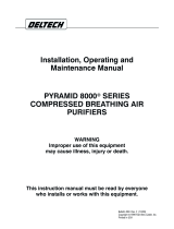
See schematic drawing, Figure 1. The purifier is designed
specifically to treat compressed air for supplied breathing air
systems. To insure its functional operation, proper installation
is vital.
NOTE: Inlet and outlet isolation valves, drain and bleed valves
should be kept in closed position at all times when purifier is
not in operation.
Figure 1
in (mm)
1.3 Cartridge
A. Purifier is shipped with convertor cartridge separately car-
toned. This cartridge must be installed prior to operation.
See Section 5.2 for installation instructions.
2.0 DESIGN LIMITATIONS
A. Flow - nominal 10 scfm at 100 psig (7.03 kg/cm
2
)
B. Maximum working pressure - 200 psig (14.06 kg/cm
2
)
standard
C. Maximum operating temperature - 120°F (48.9°C)
D. Chemical attack - compressed air does not normally
contain contaminants which will adversely affect this
purifier. However, aromatic and chlorinated hydrocarbons,
acids, bases and certain other chemicals can attack parts
of the filter assemblies and result in personal injury.
On questionable applications, the factory should be
consulted prior to installation or operation.
TABLE 1
Recommended maximum flow rates at various operating
pressures.
Inlet Pressure psig
kgf/cm2
20
(1.4)
40
(2.8)
60
(4.2)
100
(7.0)
150
(10.6)
200
(14.0)
Flow Rate scfm
m3/hr
3.0
5.1
4.8
8.2
6.5
11.0
10.0
17.0
14.4
24.5
18.7
31.8
SHIPPING
WEIGHT
34 lbs. (15.4 kg)
1
6
3
42
5
7
8
205/8 (524)
213/16 (71)
12 (305)
321/8
(822)
6 (152)
Minimum Clearance
Required for Service
Air Outlet
1/2 - 14 NPT
Air Inlet
1/2 - 14 NPT
61/2 (165)
319/32 (91)
51/2 (140)
OPEN
OPEN
1. Filter
2. Convertor
3. Indicator
4. Isolation Valves
5. Mounting Bracket
6. Drain Valve
7. Indicator Bleed & Check Valve
8. Differential Pressure Gauge
NOTE: Remove plastic protectors from isolation valves,
indicator bleed valve, filter and convertor drain valves,
and convertor head.
1.2 Mounting
A. Install so inlet and outlet connections are horizontal
and so that all cartridges are in a vertical position. Tipping
of cartridges from the vertical orientation can impede
drainage and/or reduce their efficiency. Allow a minimum
of 6" (152 mm) below the bottom edge of the convertor
case for cartridge replacement.
B. Bolt mounting bracket to wall or other support member
by means of (4) 5/16" fasteners.

3
3.0 OPERATION
A. The purifier, when installed properly and operated within
its design limitations, will effectively purify compressed
air at system pressure so that it can be utilized, after
appropriate pressure reduction, with respirators, hoods
and similar breathing apparatus. It will remove liquid and
solid contaminants, odors and many toxic gases including
carbon monoxide. (Traces of hydrogen sulfide, sulfur di-
oxide, nitrogen dioxide, and miscellaneous organic gases
[not methane]) Treated air purity either meets or exceeds
OSHA standard for breathing air (See Table 2.) Although
the purifier will eliminate the impurities commonly found
in compressed air, care should be exercised in the location
of the air compressor intake to avoid very high concen-
trations of impurities or unusual toxic contaminants from
being introduced into the system.
Occupational Safety and Health Regulations (1910.134d)
These regulations correspond to the Commodity
Specification for Air, Compressed Gas Association Inc. - (CGA
Specifications G-7.1 Type 1, Grade D).
(1) The OSHA standard also states that compressed breathing air shall meet at leat the
requirements for Type-1 Grade 2 breathing aire described in ANSI/Compressed Gas
Association Commodity Specification for Air ANSI/CGA G-7.1-1989.
(2) The CSA standard lists levels for a number of additional contaminants (methane. non-
methane hydrocarbons, nitrogen dioxide, nitrous oxide, halodenated hydrocarbons) and
includes by reference contaminants documented by the ACGIH for chemical substances and
physical agents in the workroom environment. The purifier will remove only those gaseous
contaminants normally adsorbable by activated carbon.
* At rated conditions, the purifier will reduce CO concentrations up to 400 PPM v/v to
below allowable limits.
** Since CO is converted to CO2 by the purifier, high concentrations of CO in the system
and/or high concentrations of CO2 at the compressor intake could result in exceeding
allowable Co2 limits.
***Will remove gaseous hydrocarbons normally adsorbable by activated carbon.
B. Before and during operation, it is necessary to make
certain checks to insure satisfactory performance.
1. Check to see that lines downstream of the purifier
are clean and free of materials which could show up
at the point of use of the air.
2. Check to see that the filter and convertor are
installed level. This is necessary to insure adequate
drainage.
3. Check the flow, pressure, and temperature to insure
that the purifier is being operated within design
limitations.
4. Check Indicator - DO NOT OPEN PURIFIER OUTLET
ISOLATION VALVE IF UPPER INDICATOR BAND IS YELLOW.
a. With outlet isolation valve closed and purifier
pressurized, open indicator bleed valve until
upper indicator band turns green (approximately
5 minutes).
b. After upper indicator band has turned green,
close indicator bleed valve. (Note: A fixed orifice
will allow a small and continuous bleed of air to
flow through the indicator.)
c. Open outlet isolation valve to place purifier in
operation.
d. Low indicator band should gradually turn green
during operation.
e. Periodically (about every 30 minutes), check to
see that upper indicator band is green.
During this check, establish that indicator has
slight bleed flow.
f. When upper indicator band turns yellow,
convertor cartridge should be replaced.
g. Lower indicator band will begin to turn yellow
if cartridge is not replaced. Cartridge must be
replaced before lower indicator band turns
completely yellow to avoid toxic levels of carbon
monoxide from passing through the purifier.
TABLE 2
Contaminant Maximum Allowable
Concentrations
Catalite Air
Purifier Outlet
Concentrations at
Rated Operating
Conditions
OSHA (1) CSA (2)
Carbon Monoxide (CO)
PPM v/v 10 5
Normally
below 10*
Carbon Dioxide (CO2)
PPM v/v 1000 500
Normally below
1000**
Condensed
Hydrocarbons mg/m35 1 0 to 0.2
Odor Not Noticeable Not Detectable None***
Moisture Content
dew point temperature
10°F (5.6°C)
below ambient
temperature
(at 1 atm.
pressure)
9°F (5°C)
below the min.
temperature
breathing air
is exposed to
(at lime pressure)
-40°F (-40°C) at line pressure,
-71°F (-57°C) when purified
@ 100 psig and reduced to 1
atm. pressure acceptable for
life of cartridge

4
TABLE 3
Maximum Theoretical Life (MTL) in scf at various inlet
pressure dew points and pressures.
Inlet dew point
(saturated air)
temperature
°F (°C)
Inlet Pressure psig (kgf/cm2)
20
(1.4)
40
(2.8)
60
(4.2)
80
(5.6)
100
(7.0)
150
(10.5)
200
(14.1)
40 (4)
50 (10)
60 (16)
6,798
4,644
3,230
10,716
7,321
5,091
14,634
9,998
6,953
18,552
12,675
8,814
22,470
15,352
10,676
32,265
22,044
15,330
42,060
28,736
19,984
70 (21)
80 (27)
2,281
1,634
3,596
2,575
4,911
3,517
6,226
4,458
7,541
5,400
10,828
7,754
14,116
10,108
90 (32)
100 (38)
1,186
872
1,869
1,375
2,552
1,876
3,236
2,380
3,919
2,883
5,627
4,140
7,336
5,397
4.0 MAINTENANCE
THE PURIFIER IS A PRESSURE CONTAINING
DEVICE. DEPRESSURIZE BEFORE SERVICING.
A. Periodically drain the two (2) vessels.
1. Filter - Before liquid level reaches cartridge bottom
cap.
2. Convertor - Each time cartridge is replaced or when
purifier is taken out of operation.
4.1 Procedure for Filter Element Replacement
(See Section 5 for cartridge replacement procedure.)
A. Filter - When pressure drop across the filter exceeds
10 psi, or when pressure drop across the purifier exceeds
15 psi.
1. The filter is supplied with a differential pressure
gauge. Pressure differential in excess of 10 psi
(0.7 kgf/cm
2
) - pressure indicator in red area -
indicates that the element should be replaced.
B. Convertor - When upper indicator band changes from
green to yellow.
C. Determine Cartridge life
1. Determine cartridge life at actual operating
conditions. At 80°F saturated inlet compressed air
temperature and 100 psig inlet pressure, a cartridge
will purify 5400 standard cubic feet of air.
2. Determine cartridge life at other conditions as
follows:
Step 1 - From Table 3, find Maximum Theoretical Life
(MTL) in standard cubic feet (scf) that model 1901 can
handle at the pressure and dew point temperature at
the inlet to the purifier.
Step 2 - If the inlet air is less than 100% saturated
(dew point temperature is less than sensible
temperature), adjust MTL for level of saturation.
Refer to Table 4 and find the Saturated Air Correction
Factor (SACF) at the intersection of the dew point
and sensible temperatures corresponding to your
operating conditions.
Step 3 - Multiply MTL from step 1 by SACF to get
adjusted MTL.
Step 4 - To find actual life in minutes, divide adjusted
life found in Step 3 by flow requirements of
breathing apparatus.
EXAMPLE - Determine cartridge life at the following
conditions:
Flow requirement: 5 scfm
Inlet pressure: 100 psig
Inlet sensible temperature: 80°F
Inlet dew point temperature: 40°F
Step 1 - Find MTL from Table 3 at 40°F and 100 psig.
MTL = 22,470 scf.
Step 2 - Find SACF from Table 4 for 40°F dew point and
80°F sensible temperatures. SACF = 0.28
Step 3 - Find adjusted MTL by multiplying MTL by SACF.
22,470 x 0.28 = 6292
Step 4 - Find cartridge life in minutes by dividing
adjusted MTL from Step 3 by flow requirement, 5 scfm.
6292÷5 =1258 minutes (21 hours)
TABLE 4
Saturated Air Correction Factor (SACF)
Dew point (saturated air) temperature
120°F (49°C) 1.00
110°F (43°C) 1.00 0.90
100°F (38°C) 1.00 0.90 0.78
90°F (32°C) 1.00 0.90 0.75 0.56
80°F (27°C) 1.00 0.88 0.70 0.51 0.39
70°F (21°C) 1.00 0.88 0.70 0.51 0.36 0.28
60°F (16°C) 1.00 0.88 0.69 0.50 0.34 0.25 0.21
50°F (10°C) 1.00 0.85 0.65 0.45 0.30 0.22 0.19 0.19
40°F (4°C) 1.00 0.87 0.65 0.42 0.28 0.19 0.15 0.13 0.13
40°F
(4°C)
50°F
(10°C)
60°F
(16°C)
70°F
(21°C)
80°F
(27°C)
90°F
(32°C)
100°F
(38°C)
110°F
(43°C)
120°F
(49°C)
Sensible temperature

5
5.0 CARTRIDGE REPLACEMENT PROCEDURE
THE PURIFIER IS A PRESSURE CONTAINING DE-
VICE. DEPRESSURIZE BEFORE REPLACING ANY CARTRIDGE.
5.1 Filter Cartridge No. 0713-2-1
1. Close inlet and outlet isolation ball valves. Depressurize
the filter by slowly opening manual drain as shown.
2. Unscrew the metal collar holding the filter bowl to the
head and remove the filter bowl and collar. Clean the filter
bowl.
3. Unscrew the old filter cartridge and discard. Also discard
the small o-ring that seals the filter cartridge top cap to
the filter assembly head.
4. Insert small replacement o-ring on top of new replace-
ment filter cartridge and screw replacement filter
cartridge into filter assembly head. It is only necessary to
finger tighten the filter cartridge into position to insure
the seal. DO NOT WRENCH TIGHTEN.
THE FILTER CARTRIDGE SHOULD NEVER BE
HANDLED BY ITS OUTSIDE FOAM COVER. DAMAGE CAN RE-
SULT. WHEN INSTALLING A REPLACEMENT FILTER CARTRIDGE, IT
SHOULD BE HELD BY THE BOTTOM END CAP ONLY. (See Drawing)
5. Replace filter bowl and screw collar onto filter assembly
head.
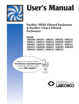
5.2 Convertor Cartridge P/N 3154050
1. Disconnect spring which holds convertor case to bracket.
2. Using hands or strap wrench, unscrew case collar and
lower case assembly vertically downward to clear used
cartridge. If insufficient space is available to clear car-
tridge, allow case to rest on floor and proceed to next
step.
3. Unscrew used cartridge and remove cartridge and bowl
assembly.
4. Remove 5/16" nut and sleeve seal assembly from top of
used cartridge.
5. Open new cartridge bag. Replacement cartridges are
furnished in a dated vapor barrier bag. (NOTE: DO NOT
OPEN VAPOR BARRIER BAG UNTIL READY TO INSTALL NEW
CARTRIDGE.)
6. Insert new 1-7/8" I.D. x 2" O.D. o-ring in o-ring groove on
top cap of new cartridge.
7. Fasten sleeve seal assembly to top of new cartridge.
Check to see that o-ring is properly seated in top cap o-
ring groove.
8. Insert new 1-3/4" I.D. x 1-7/8" O.D. o-ring in sleeve seal.
9. Check convertor case to see that cartridge support spring
is positioned in the bottom of the case.
10. Screw cartridge into head and hand tighten. Install case
and hand tighten collar. (If bottom edge of mounting
bracket is less than 45 inches above floor, place cartridge
in case and position both below head before installing
cartridge.) Hand tightening of cartridge and case is
adequate to insure seals. DO NOT USE WRENCH TO
TIGHTEN CARTRIDGE.
11. Reconnect convertor case retaining spring.
12. Prior to placing air purifier into service, observe purifier
warning labels. Do not open purifier outlet isolation valve
if upper indicator band is yellow. See Section 3.0.
NOTE: DO NOT USE A WRENCH TO TIGHTEN THIS EQUIPMENT.
OPEN ( TO RIGHT )
KNURLED FITTING
Head
O-ring
1-3/4” X 1-7/8”
Sleeve Seal
Assembly
Converter
Case
Hex Nut
5/16” - 18
O-ring
1-7/8” x 2”
Cartridge
No. 0719-1
Spring

6
1. Depressurize the purifier.
2. With indicator still installed, unscrew combination bleed
and check valve assembly from indicator housing.
3. Remove lower gasket and old indicator cartridge.
4. Replace upper gasket and check to insure that it is prop-
erly seated in housing.
5. Install new indicator cartridge in housing so that thinner
band of colored granules (indicator gel) is at the top.
6. Insert new lower gasket.
7. Screw the combination bleed and check valve assembly
back into indicator housing.
6.0 GENERAL INFORMATION
1. When the purifier is not in operation, all valves should be
closed, including the vessel drain cocks and the indicator
bleed valve. The convertor cartridge and indicator vessel
contain moisture sensitive materials.
NOTE: When indicator bleed valve is closed and system
is not in operation, an integral check valve will prevent
atmospheric air from entering and contaminating car-
tridges.
2. Replacement convertor cartridge should not be exposed
to moisture or high humidity. Do not unseal vapor bag
until immediately before installation and operation.
3. Replacement of the convertor cartridge, which is con-
sumable, is much more frequent (hours of use) than the
filter cartridge (months of use).
4. Consult factory for questionable applications or when in
doubt about intended usage.
PARTS LIST
Description Part
Number
Cartridge
Replacement No.
Filter
Convertor Case
Moisture Indicator
3154029
3154185
4003168
0713-2-1
3154050
3154165
Isolating Valve (2)
Drain Cock (Manual) (2)
Bleed & Check Valve Assembly
Spring
4009899
3154103
3154199
3154187
Bracket
O-ring 1-3/4 ID x 1-7/8 OD
Nut Hex 5/16-18
Sleeve Seal Assembly
O-ring 1-7/8 ID x 2 OD
3154034
3154404
3154135
3154411
3154405
Inlet
Orifice
Indicator
Housing
Upper Gasket
Indicator
Tube
Lower Gasket
Combination Bleed &
Check Assembly
INLET
ORIFICE
INDICATOR
HOUSING
UPPER
GASKET
INDICATOR
TUBE
LOWER GASKET
COMBINATION
BLEED & CHECK
VALVE ASSEMBLY
5.3 Indicator Kit P/N 3154165


WARRANTY
The manufacturer warrants the product manufactured by it, when properly installed, operated, applied, and maintained
in accordance with procedures and recommendations outlined in manufacturer’s instruction manuals, to be free from
defects in material or workmanship for a period as specified below, provided such defect is discovered and brought to
the manufacturer’s attention within the aforesaid warranty period.
The manufacturer will repair or replace any product or part determined to be defective by the manufacturer within
the warranty period, provided such defect occurred in normal service and not as a result of misuse, abuse, neglect or
accident. Normal maintenance items requiring routine replacement are not warranted. The warranty covers parts and
labor for the warranty period unless otherwise specified. Repair or replacement shall be made at the factory or the
installation site, at the sole option of the manufacturer. Any service performed on the product by anyone other than the
manufacturer must first be authorized by the manufacturer.
Unauthorized service voids the warranty and any resulting charge or subsequent claim will not be paid. Products
repaired or replaced under warranty shall be warranted for the unexpired portion of the warranty applying to the original
product.
The foregoing is the exclusive remedy of any buyer of the manufacturer’s product. The maximum damages liability of
the manufacturer is the original purchase price of the product or part.
THE FOREGOING WARRANTY IS EXCLUSIVE AND IN LIEU OF ALL OTHER WARRANTIES, WHETHER WRITTEN, ORAL, OR
STATUTORY, AND IS EXPRESSLY IN LIEU OF THE IMPLIED WARRANTY OF MERCHANTABILITY AND THE IMPLIED WARRANTY OF
FITNESS FOR A PARTICULAR PURPOSE. THE MANUFACTURER SHALL NOT BE LIABLE FOR LOSS OR DAMAGE BY REASON OF
STRICT LIABILITY IN TORT OR ITS NEGLIGENCE IN WHATEVER MANNER INCLUDING DESIGN, MANUFACTURE OR INSPECTION OF
THE EQUIPMENT OR ITS FAILURE TO DISCOVER, REPORT, REPAIR, OR MODIFY LATENT DEFECTS INHERENT THEREIN.
THE MANUFACTURER, HIS REPRESENTATIVE OR DISTRIBUTOR SHALL NOT BE LIABLE FOR LOSS OF USE OF THE PRODUCT OR
OTHER INCIDENTAL OR CONSEQUENTIAL COSTS, EXPENSES, OR DAMAGES INCURRED BY THE BUYER, WHETHER ARISING FROM
BREACH OF WARRANTY, NEGLIGENCE OR STRICT LIABILITY IN TORT.
The manufacturer does not warrant any product, part, material, component, or accessory manufactured by others and
sold or supplied in connection with the sale of manufacturer’s products.
AUTHORIZATION FROM THE SERVICE DEPARTMENT IS NECESSARY BEFORE MATERIAL IS RETURNED TO THE
FACTORY OR IN-WARRANTY REPAIRS ARE MADE.
/