13
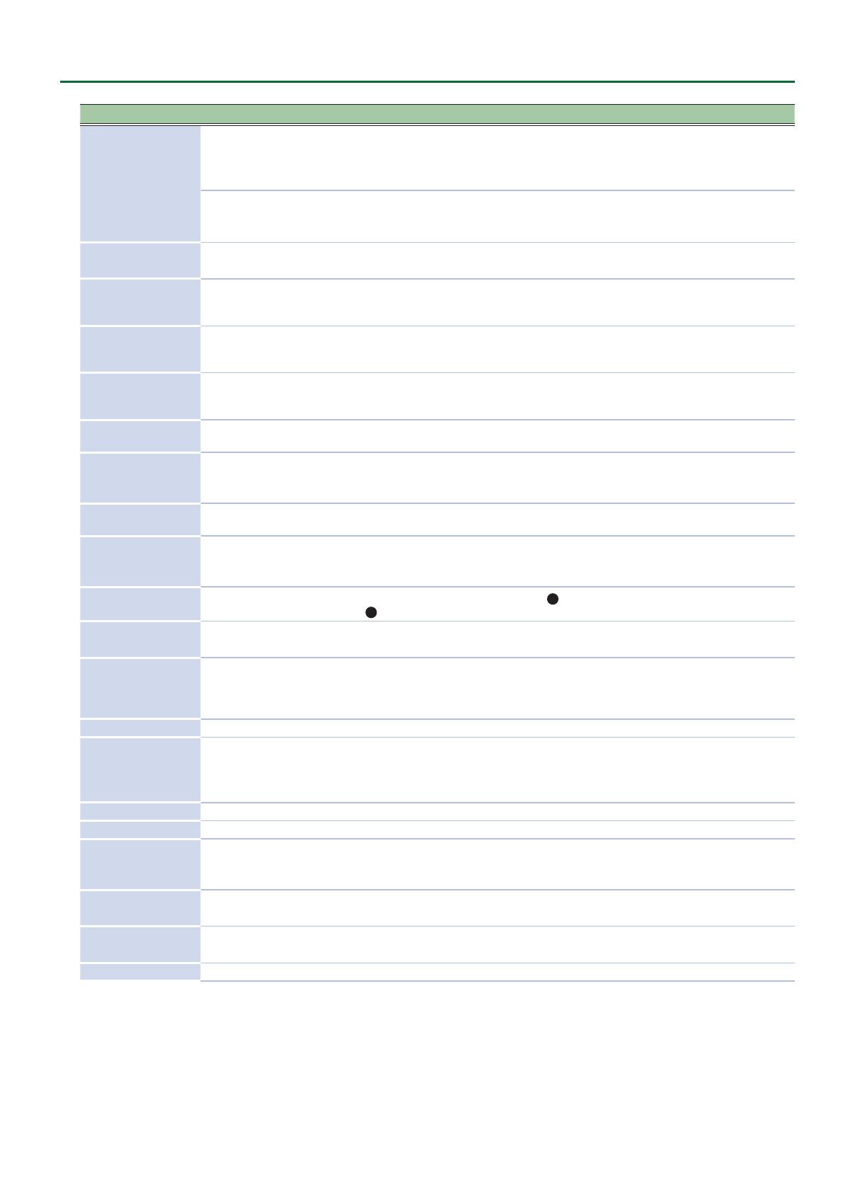
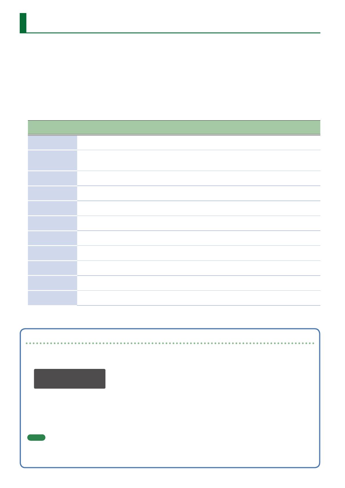
Patch Eects
Parameter
Presence/absence of parameters for each
type
Value Explanation
DLY PAN CH1 CH2 FL
DLY +
CH
DlyHDmpF
6 6
– – –
6
630Hz, 800Hz, 1kHz, 1.25kHz, 1.6kHz,
2kHz, 2.5kHz, 3.15kHz, 4kHz, 5kHz,
6.3kHz, 8kHz, 10kHz, 12.5kHz
Species the frequency above which
the DlyHDmp setting cuts the sound.
DlyLDmp
6 6
– – –
6
0.0dB–-40.0dB (0.5 dB steps), -INF
Adjusts the amount by which the
low-frequency region is cut each
time the delay sound is repeated.
DlyLDmpF
6 6
– – –
6
80.0Hz, 100Hz, 125Hz, 160Hz, 200Hz,
250Hz, 315Hz, 400Hz, 500Hz, 630Hz,
800Hz
Species the frequency below which
the DlyLDmp setting cuts the sound.
DlyDirLev
6 6
– – –
6
0–255
Adjusts the volume of the direct
sound.
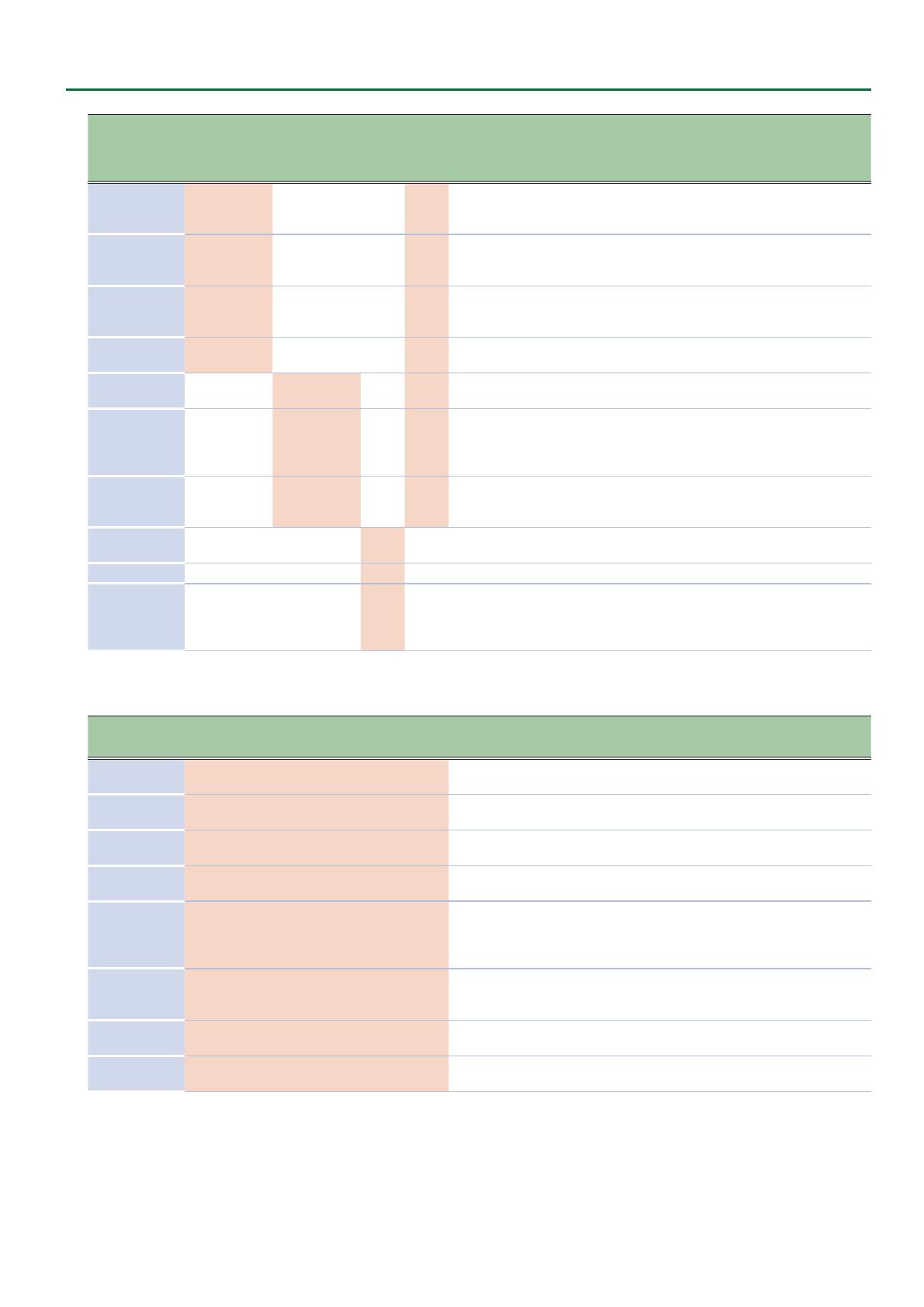
ChPreDly – –
6 6
–
6
0.0ms–40.0ms (0.5 ms steps)
Adjusts the time until the chorus
sound is output.
ChLoCut – –
6 6
–
6
FLAT, 20Hz, 25Hz, 31.5Hz, 40Hz,
50Hz, 63Hz, 80Hz, 100Hz, 125Hz,
160Hz, 200Hz, 250Hz, 315Hz, 400Hz,
500Hz, 630Hz, 800Hz
Species the frequency below which
the low-frequency region of the
chorus sound is cut.
ChHiCut – –
6 6
–
6
630Hz, 800Hz, 1kHz, 1.25kHz, 1.6kHz,
2kHz, 2.5kHz, 3.15kHz, 4kHz, 5kHz,
6.3kHz, 8kHz, 10kHz, 12.5kHz, FLAT
Species the frequency above which
the high-frequency region of the
chorus sound is cut.
FlManual – – – –
6
– 0–255
Adjusts the center frequency at
which the anger eect is applied.
FlReso – – – –
6
– 0–255 Adjusts the amount of resonance.
FlLoCut – – – –
6
–
FLAT, 20Hz, 25Hz, 31.5Hz, 40Hz,
50Hz, 63Hz, 80Hz, 100Hz, 125Hz,
160Hz, 200Hz, 250Hz, 315Hz, 400Hz,
500Hz, 630Hz, 800Hz
Species the frequency below which
the low-frequency region of the
anger sound is cut.
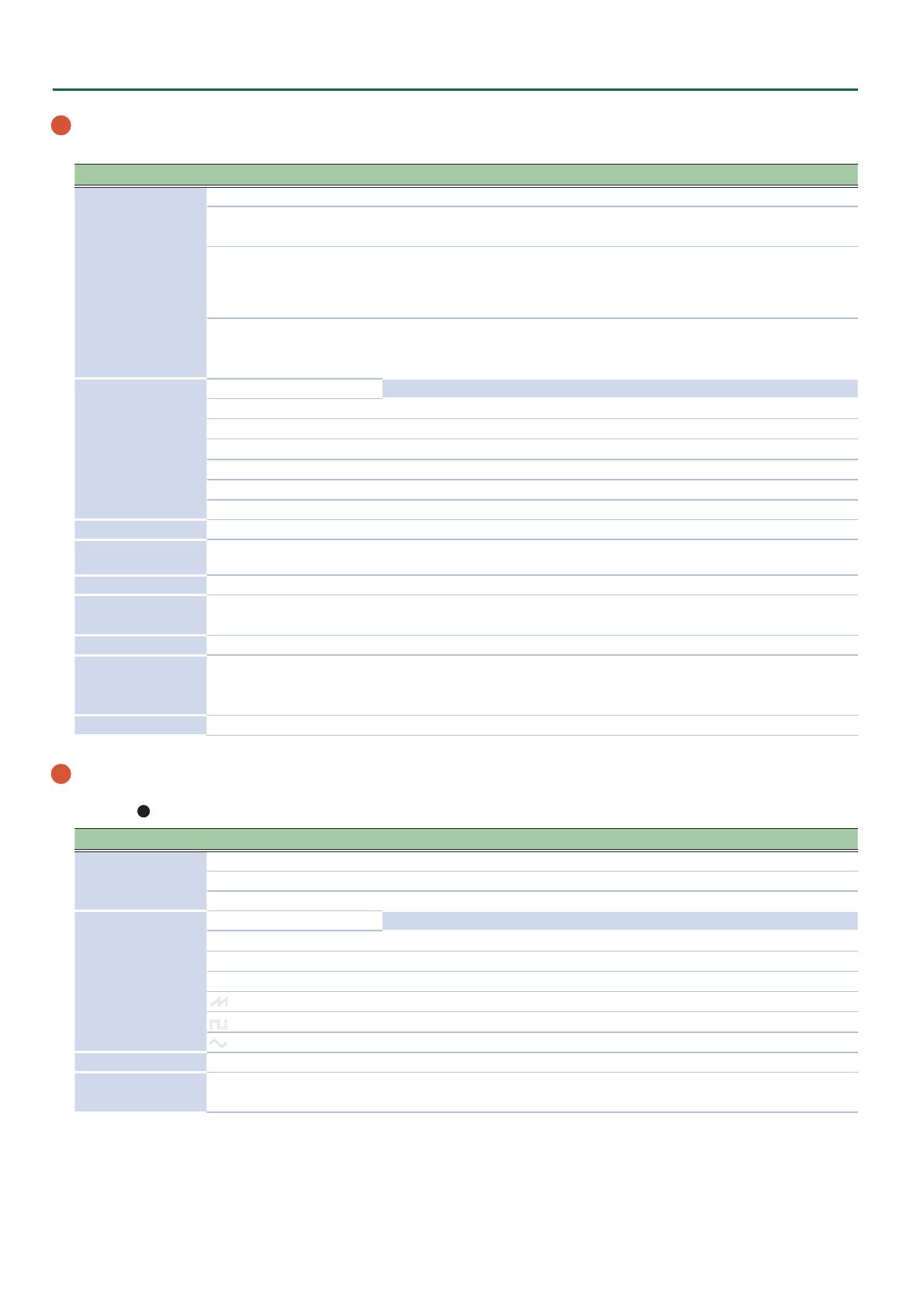
REVERB parameters
Parameter
Presence/absence of parameters
Value Explanation
AMBI ROOM HALL1 HALL2 PLATE MOD
Type
6 6 6 6 6 6
AMBIENCE, ROOM, HALL 1, HALL 2,
PLATE, MODULATION
Switches the reverb type.
Time
6 6 6 6 6 6
0–255
Adjusts the length of the reverb
decay.
Level
6 6 6 6 6 6
0–255
Adjusts the volume of the reverb
sound.
Pre Delay
6 6 6 6 6 6
0ms–100ms
Adjusts the time until the reverb
sound is output.
Low Cut
6 6 6 6 6 6
FLAT, 20Hz, 25Hz, 31.5Hz, 40Hz,
50Hz, 63Hz, 80Hz, 100Hz, 125Hz,
160Hz, 200Hz, 250Hz, 315Hz, 400Hz,
500Hz, 630Hz, 800Hz
Species the frequency below which
the low-frequency region of the
reverb sound is cut.
High Cut
6 6 6 6 6 6
630Hz, 800Hz, 1kHz, 1.25kHz, 1.6kHz,
2kHz, 2.5kHz, 3.15kHz, 4kHz, 5kHz,
6.3kHz, 8kHz, 10kHz, 12.5kHz, FLAT
Species the frequency above which
the high-frequency region of the
reverb sound is cut.
Density
6 6 6 6 6 6
0–10
Adjusts the density of the reverb
sound.
Direct Level
6 6 6 6 6 6
0–255
Adjusts the volume of the direct
sound.
4. Press the [EXIT] button to return to the MENU screen.
5. Press the [EXIT] button several times to return to the top screen.
If you want to keep the settings, save the patch.
&
“Saving a Patch (WRITE)” (p. 10)