Page is loading ...

Millerfi
May
1993
Form:
OM-138
426C
OWNERS
MANUAL
Robot
Interface
(Per
NSPR
8945)
U
U
Read
and
follow
these
instructions
and
all
safety
blocks
carefully.
Have
only
trained
and
qualified
persons
install,
operate,
or
service
this
unit.
U
Give
this
manual
to
the
operator.
For
help,
call
your
distributor
U
Call
your
distributor
if
you
do
not
understand
the
directions.
E~J
U
or:
MILLER
ELECTRIC
Mfg.
1079,
Appleton,
WI
54912
Co.,
P.O.
Box
414-734-9821
cover
8/92
PRINTED
IN
USA


I
MILLERS
TRUE
BLUETM
LIMITED
WARRANTY
Effective
January
1,
1992
(Equipment
with
a
serial
number
preface
of
KC
or
newer)
This
limited
werrenty
supersedes
eli
previous
MILLER
warranties
end
is
enclusive
with
no
other
guerantees
or
werrenties
espressed
or
implied.
al
LIMITED
WARRANTY
Sub)ect
to
the
terms
and
conditions
below,
MILLER
Electric
MIg.
Co.,
Appleton,
Wisconsin,
werrents
to
Its
original
retell
purcheser
that
new
MILLER
equipment
sold
after
the
effective
dete
of
this
limited
warranty
is
free
of
de
fects
in
material
end
workmenship
at
the
time
it
Is
shipped
by
MILLER.
TIllS
WAR
RANTY
IS
EXPRESSLY
IN
LIEU
OF
ALL
OTHER
WARRANTIES,
EXPRESS
OR
IMPLIED.
INCLUDING
THE
WARRANTIES
OF
MERCHANTABILITY
AND
FIT
NESS.
Within
the
warrant~
periods
listed
below,
MILLER
will
repeir
or
replace
eny
war-
rented
parts
or
components
that
tail
due
to
such
detects
in
material
or
wortcmenship.
MILLER
must
be
notified
in
writing
within
thirty
(30)
days
of
such
defect
or
failure,
at
which
time
MILLER
will
provide
instructions
on
the
warranty
claim
procedures
to
be
followed.
MILLER
shell
honor
warranty
claims
on
warranted
equipment
listed
below
in
the
event
of
such
a
failure
within
the
warranty
time
periods.
All
warranty
time
periods
start
on
the
data
that
the
equipment
was
delivered
to
the
original
retail
purchaser,
or
one
year
ahar
the
equipment
is
sent
to
the
distributor.
1.
5
Years
Parts
3
Years Labor
Original
main
power
ractifiars
2.
3
Years
Parts
and
Labor
*
Transformer/Rectifier
Power
Sources
Plasma
Arc
Cutting
Power
Sources
*
Semi-Automatic
and
Automatic
Wire
Feeders
*
Robots
3.
2
Years
Parts
and
Labor
*
Engine
Driven
Welding
Generators
(NOTE:
Engines
ara
warranted
separately
by
the
angina
manufacturer.)
*
Air
Compressors
4.
1
Year
Parts
and
Labor
5.
6.
*
Motor
Driven
Guns
*
Procsss
Controllers
*
Water
Coolant
Systems
*
HF
Units
*
Grids
*
Spot
Welders
*
Load
Banks
*
SDX
Transformers
Running
Gear/Trailers
*
Field
Options
(NOtE:
Field
options
are
covered
under
True
BIueTU
br
the
remaining
warrØnty
period
of
the
product
they
are
installed
in,
or
for
a
minimum
of
one
year
whichever
is
greater.)
6
Months
Batteries
90
Days
Parts
and
Labor
*
MIG
Guns/TIG
Torches
Plasma
Cutting
Torchas
-4>
*
Remote
Controls
Accessory
Kits
*
Replacement
Parts
MILLERS
True
BluerM
Limited
Warranty
shatl
not
appty
to:
1.
Items
furnished
by
MILLER,
but
manufactured
by
others,
such
ss
engines
or
trade
accessories.
These
items
are
covered
by
the
manufacturers
warranty,
If
any.
2.
Consumable
components;
such
as
contact
tips,
cutting
nozzles,
contactors
and
relays
or
parts
that
fail
due
to
normal
wear.
3.
Equipment
that
has
been
modified
by
any
party
other
than
MILLER,
or
equip
ment
that
has
been
improperly
installed,
improperly
operated
or
misused
based
upon
industry
standards,
or
equipment
which
has
not
had
reasonable
and
necessary
maintenance,
or
equipment
which
has
bean
used
for
operation
outside
of
the
specifications
for
the
equipment.
MILLER
PRODUCTS
ARE
INTENDED
FOR
PURCHASE
AND
USE
BY
COMMER
CiALJINDUSTRIAL
USERS
AND
PERSONS
TRAINED
AND
EXPERIENCED
IN
THE
USE
AND
MAINTENANCE
OF
WELDING
EGUIPMENT
In
the
avant
of
a
warranty
claim
covered
by
this
warranty,
the
esclusive
remedies
shall
be,
at
MILLERS
option:
(t)
repair;
or
(2)
replacement;
or.
where
authorized
in
writing
by
MILLER
Inappropriate
cases,
(3)
the
reasonable
cost
of
repair
or
replace
ment
at
an
authorized
MtLLER
service
station;
or
)4)
paymant
of
orcredit
for
the
pur
chase
price
(less
reasonable
depreciation
based
upon
actual
use)
upon
return
of
the
goods
at
customers
risk
end
espense.
MILLERS
option
of
repair
or
rsplscament
will
be
FOB.,
Factory
at
Appleton.
Wisconsin,
or
FOB.
at
a
MILLER
authorized
ser
vice
facility
as
determined
by
MILLER.
Therefore
no
compensation
or
reimburse
ment
for
transportation
costs
of
any
kind
will
be
allowed.
TO
THE
EXTENT
PERMItTED
BY
LAW.
THE
REMEDtES
PROVIDED
HEREIN
ARE
THE
SOLE
AND
EXCLUSIVE
REMEDIES.
IN
NO
EVENT
SHALL
MILLER
BE
LtABLE
FOR
DIRECT,
INDIRECt
SPECIAL,
INCIDENTAL
OR
CONSEOUENTIAL
DAMAGES
(INCLUDING
LOSS
OF
PROFIT).
WHETHER
BASED
ON
CON
TRACt
TORT
OR
ANY
OTHER
LEGAL
THEORY.
ANY
EXPRESS
WARRANTY
NOT
PROVIDED
HEREIN
AND
ANY
IMPLIED
WAR
RANTY,
GUARANTY
OR
REPRESENTATION
AS
TO
PERFORMANCE,
AND
ANY
REMEDY
FOR
BREACH
OF
CONTRACT
TORT
OR
ANY
OTHER
LEGAL
THEORY
WHICH,
BUT
FOR
THIS
PROVISION,
MIGHT
ARISE
BY
IMPLICATION,
OPERATION
OF
LAW.
CUSTOM
OF
TRADE
OR
COURSE
OF
DEALING,
IN
CLUDING
ANY
IMPLIED
WARRANTY
OF
MERCHANTABILtTY
OR
FITNESS
FOR
PARTtCULAR
PURPOSE.
WITH
RESPECT
TO
ANY
AND
ALL
EOUIPMENT
FURNISHED
BY
MILLER
IS
EXCLUDED
AND
DtSCLAIMED
BY
MILLER.
Some
states
in
the
U.S.A.
do
not
allow
limitations
of
how
long
an
Implied
warranty
lasts,
or
the
esclusion
of
incidental,
indirect,
special
or
consequential
damages,
so
the
above
limitation
or
esclusion
may
not
apply
to
you.
This
warranty
provides
spe
cific
legal
rights,
and
other
rights
may
be
available,
but
may
vary
from
state
to
state.
In
Canada,
legislation
in
some
provinces
provides
for
certain
additional
warranties
or
remedies
other
than
as
stated
herein,
and
to
the
estant
that
they
may
not
be
waived,
the
limitations
and
escluslons
set
out
above
may
not
apply.
This
Limited
Warranty
provides
specific
legal
rights,
and
other
rights
may
be
available,
but
may
vary
from
province
to
province.
RECEIVING-HANDLING
Before
unpaCking
equipment,
check
carton
for
any
damage
that
may
have
oCcurred
during
shipment.
File
any
claims
for
loss
or
damago
with
the
delivering
carrier.
Assistance
for
filing
or
settling
claims
may
be
obtained
from
distributor
and/or
equipment
manufacturers
Transportation
Department.
When
requesting
information
about
this
equipment,
always
provide
Mode)
Designation
and
Serial
or
Style
Number.
Use
the
following
spaces
to
record
Model
Designation
and
Ser)al
or
Style
Number
of
your
unit.
The
information
is
located
on
the
rating
label
or
nameplate.
Mode)
_________
Serial
or
Style
No.
Date
of
Purchase
miller
5/93e


TABLE
OF
CONTENTS
SECTION
1
SAFETY
PRECAUTIONS
AND
SIGNAL
WORDS
1-1.
General
Information
And
Safety
1
1-2.
Safety
Alert
Symbol
And
Signal
Words
1
SECTION
2
SPECIFICATIONS
2-1.
Description
1
SECTION
3INSTALLATION
3-1.
Site
Selection
2
3-2.
Equipment
Installation
2
3-3.
Gas/Current
Sensing
Control
Interconnections
2
3-4.
Voltage
Sensing
Connections
3
3-5.
Robot
Interface
Welding
Power
Source
Connections
3
3-6.
Robot
Interface
Robot
Control
Unit
Connections
4
3-7.
Arc
Failure
Light
Terminal
Strip
Connections
5
3-8.
Welding
Wire
Installation
5
SECTION
4
OPERATOR
CONTROLS
4-1.
Power
Switch
6
4-2.
Jog
Push
Buttons
6
4-3.
Purge
Push
Button
6
4-4.
Voltmeter
6
4-5.
Wire
Speed
Meter
7
4-6.
Peak
Amps/Inductance
Meter
7
4-7.
Indicator
Lights
7
4-8.
Burnback
Control
7
SECTION
5-
SEQUENCE
OF
OPERATION
5-1.
Input
Signals
From
Robot
Control
Unit
7
5-2.
Output
Signals
From
Robot
Interface
7
SECTION
6
MAINTENANCE
&
TROUBLESHOOTING
6-1.
Routine
Maintenance
7
6-2.
Overload
Protection
8
6-3.
Reinstallation
Of
Hub
Assembly
8
6-4.
Display
Board
P04
Meter
Check
8
6-5.
Circuit
Board
Handling
Precautions
9
SECTION
7
ELECTRICAL
DIAGRAMS
Diagram
7-1.
Circuit
Diagram
For
Robot
Interface
10
Diagram
7-2.
Circuit
Diagram
For
Gas/Current
Control
11
SECTION
8
PARTS
LIST
12
LIST
OF
CHARTS
AND
TABLES
Table
2-1.
Specifications
1
CM-I
38
426C
5(93


SECTION
1
SAFETY
PRECAUTIONS
AND
SIGNAL
WORDS
1-1.
GENERAL
INFORMATION
AND
SAFETY
1-2.
SAFETY
ALERT
SYMBOL
AND
SIGNAL
WORDS
A.
General
The
following
safety
alert
symbol
and
signal
words
are
Information
presented
in
this
manual
and
on
various
Ia-
usedthroughoutthismanualtocallattentiontoandiden
bels,
tags,
and
plates
on
the
unit
pertains
to
equipment
tify
different
levels
of
hazard
and
special
instructions.
design,
installation,
operation,
maintenance,
and
/%~
This
safety
alert
symbol
is
used
with
the
signal
troubleshooting
which
should
be
read,
understood,
and
~
words
WARNING
and
CAUTION
to
call
atten
followed
for
the
safe
and
effective
use
of
this
equipment.
tion
to
the
safety
statements.
B.
Safety
WARNING
statements
identify
procedures
or
The
installation,
operation,
maintenance,
and
trouble-
practices
which
must
be
followed
to
avoid
seri
shooting
of
arc
welding
equipment
requires
practices
ous
personal
injury
or
loss
of
life.
and
procedures
which
ensure
personal
safety
and
the
safety
of
others.
Therefore,
this
equipment
is
to
be
in-
CAUTION
statements
identify
procedures
or
stalled,
operated,
and
maintained
only
by
qualified
per-
practices
which
must
be
followed
to
avoid
minor
sons
in
accordance
with
this
manual
and
all
applicable
personal
injury
or
damage
to
this
equipment.
codes
such
as,
but
not
limited
to,
those
listed
at
the
end
of
Section
1
Safety
Rules
For
Operation
Of
Arc
Weld-
IMPORTANT
statements
identify
special
instructions
ing
Power
Source
in
the
welding
power
source
Owners
necessary
for
the
most
efficient
operation
of
this
equip-
Manual.
ment.
SECTION
2SPECIFICATIONS
Table
2-1.
Specifications
Component
Dimensions
Weight
Height
Width
Depth
Net
Ship
Robot
Interface
22-1/2in.
(572
mm)
16-1/2in.
(419
mm)
6~1/4in.*
(159
mm)
381bs.
(17
kg)
Total
61
lbs.
(27.7
kg)
Gas/Current
Sensing
Control
4-1/2
in.
(108
mm)
8-3/4
in.
(222
mm)
14
in.
(355
mm)
5
lbs.
(2.3
kg)
Spool
Support
Assembly+
13-3/4
in.
(349
mm)
8-3/4
in.
(222
mm)
8-1/2
in.
(216
mm)
6
lbs.
(2.7
kg)
Add
2-1/4
in.
(57
mm)
for
brake
resistor.
+Spool
Support
without
optional
wire
reel.
*Add
7/8
in.
(22
mm)
for
front
panel
knob.
2-1.
DESCRIPTION
peak
amperage
or
inductance.
The
robot
interface
control
is
designed
to
interface
with
The
gas/current
sensing
control
contains
the
gas
valve,
contactor,
and
current
sensing
reed
relay.
an
Automatix
robot
and
an
Arc
Pak
350,
Deltaweld,
Max
tron,
or
Pulstar
450
welding
power
source.
This
unit
pro-
These
components
function
with
the
robot
system
when
vides
digital
display
of
weld
volts,wire
feed
speed,
and
using
the
Gas
Metal
Arc
Welding
(GMAW)
process.
OM-138
426
Page
1


SECTION
3INSTALLATION
3-1.
SITE
SELECTION
Select
an
installation
site
which
provides
the
following:
1.
Correct
input
power
supply
(see
unit
data
card)
2.
Shielding
gas
supply
(if
applicable)
3.
Water
supply
(if
applicable)
4.
Adequate
ventilation
and
fresh
air
supply
5.
No
flammables
6.
A
clean
and
dry
area
7.
Proper
temperature
that
avoids
extremes
of
heat
or
cold
8.
Proper
airflow
around
unit
9.
Adequate
space
to
open
and
remove
cover
and
wrapper
for
installation,
maintenance,
and
repair
functions.
Mounting
holes
provide
the
capability
to
install
and
se
cure
the
system
components
in
a
permanent
location.
Table
2-1
gives
overall
dimensions.
3-2.
EOUIPMENT
INSTALLATION
A.
Supplied
Equipment
The
following
equipment
is
supplied
as
standard
and
re
quires
installation
or
assembly:
1.
Weld
Control
with
Gas/Current
Sensing
Control
Cord
and
Motor
Cord
2.
Gas/Current
Sensing
Control
Hub
and
Spindle
Assembly
Spindle
Support
5.
10
ft.
(3
m)
Weld
Control
Welding
Power
Source
Interconnecting
Cords
6.
lOft.
(3m)
Gas
Hose
7.
Voltage
Sensing
Cord
B.
Equipment
Location
When
deciding
on
equipment
location,
consider
the fol
lowing:
1.
The
equipment
must
be
mounted
to
a
structure
capable
of
supporting
the
weight
of
the
equip
ment.
2.
The
lead
lengths
of
the
cords
supplied
with
the
equipment
will
limit
the
area
in
which
the
equip
ment
can
be
located.
Some
cords
can
be
ex
tended
by
using
optional
extension
cords
(check
with
welding
equipment
distributor).
3.
The
interconnecting
cords
must
be
routed
so
that
they
are
not
caught,
pinched,
or
strained
during
welding
operations.
4.
One
weld
output
cable
must
be
routed
through
the
Gas/Current
Sensing
control.
5.
Welding
wire
must
be
routed
so
that
it
does
not
contact
the
weld
control
or
any
other
grounded
equipment.
C.
Equipment
Installation
Obtain
appropriate
mounting
brackets
or
adapter
plates
as
necessary
and
mounting
hardware.
Prepare
struc
ture
for
equipment
installation.
Secure
weld
control,
Gas/Current
Sensing
control,
and
all
other
equipment
onto
structures
in
the
welding
area.
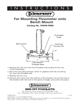
0.
Hub
Installation
(Figure
3-1)
The
hub
assembly
is
supplied
with
the
robot
interface.
Remove
the
hub
assembly
from
the
shipping
carton,
and
install
it
as
follows:
1.
Remove
hex
nut
from
end
of
hub
support
shaft.
2.
Align
keyway
and
insert
hub
support
shaft
through
selected
hole
in
hub
support.
Hole
selec
tion
in
hub
support
depends
on
wire
spool
size.
Be
sure
the
brake
washers
are
properly
seated
in
the
hub.
3.
Reinstall
hex
nut
onto
support
shaft.
Tighten
hex
nut
until
a
slight
drag
is
felt
while
turning
hub.
4.
Install
welding
wire
according
to
Section
3-8.
Figure
3-1.
Hub
Assembly
Installation
3-3.
GAS/CURRENT
SENSING
CONTROL
INTER
CONNECTIONS
(Figure
3-2)
WARNING:
ELECTRIC
SHOCK
can
kIll.
Hub
Support
Shaft
3.
4.
Hub
Assembly
Hex
Nut
Fiber
Washer
Hub
Support
SA~126
870
Do
not
touch
live
electrical
parts.
Shut
down
unit,
welding
power
source,
and
robot,
and
disconnect
input
power
employing
lockout/tagging
procedures
before
making
in
terconnections.
Lockout/tagging
procedures
consist
of
padlock
ing
line
disconnect
switch
in
open
position,
re
moving
fuses
from
fuse
box,
or
shutting
off
and
red-tagging
circuit
breaker
or
other
disconnect
ing
device.
OM-138
426
Page
2


C.
Gas
Connections
24-Socket
Receptacle
RC17
Figure
3-2.
Right
Side
View
Ref.
ST-ttg
646-B
Connect
hose
from
gas
regulator/flowmeter
(customer
supplied)
at
gas
source
to
IN
fitting
on
gas/current
sens
ing
control.
Connect
gas
hose
from
wire
drive
assembly
to
fitting
on
gas/current
sensing
control.
The
gas
flow
must
be
accurately
controlled
by
a
regulator/flowmeter
at
the
source.
D.
Motor
Connection
Align
keyways,
insert
14-pin
plug
from
motor
cord
into
matching
receptacle
RC7
on
gas/current
sensing
con
trol,
and
rotate
threaded
collar
fully
clockwise.
Weld
Cable
Lug
Location
S~O4Ol
Figure
3-3.
Voltage
Sensing
Connections
At
Wire
Drive
Assembly
3-4.
VOLTAGE
SENSING
CONNECTIONS
(Figure
3-3)
1.
Align
keyway,
insert
4-socket
plug
into
matching
receptacle
Rd
2
on
robot
interface,
and
rotate
threaded
collar
fully
clockwise.
2.
Connect
lead
with
ring
terminal
to
wire
drive
as
sembly,
along
with
the
weld
cable
from
the
weld
ing
power
source,
as
shown
in
Figure
3-3.
3.
Connect
lead
with
clamp
to
the
workpiece.
A.
Robot
Interface
Gas/Current
Sensing
Control
Connections
1.
Align
keyways,
insert
14-pin
Amp
plug
into
matching
receptacle
RC9
on
robot
interface,
and
rotate
threaded
collar
fully
clockwise.
2.
Align
keyways,
insert
16-pin
Amp
plug
into
matching
receptacle
RC1
6
on
gas/current
sens
ing
control,
and
rotate
threaded
collar
fully
clock
wise.
B.
Weld
Cable
Connections
For
Electrode
Positive/Reverse
Polarity,
route
one
cable
from
welding
power
source
POSITIVE
weld
output
ter
minal
to
the
gas/current
sensing
control,
and
connect
to
the
contactor.
Connect
second
weld
cable
to
remaining
terminal
on
contactor,
route
through
the
current
sensing
reed
relay,
to
the
wire
drive
assembly,
and
connect
cable
to
weld
cable
terminal
(see
Motor/Drive
Assembly
Own
ers
Manual
for
location).
3-5.
ROBOT
INTERFACE
WELDING
POWER
SOURCE
CONNECTIONS
(Figures
3-2
And
3-3)
a
WARNING:
ELECTRIC
SHOCK
can
kill.
Do
not
touch
live
electrical
parts.
Shut
down
unit,
welding
power
source,
and
robot,
and
disconnect
input
power
employing
lockout/tagging
procedures
before
making
in
terconnections.
Lockout/tagging
procedures
consist
of
padlock
ing
line
disconnect
switch
in
open
position,
re
moving
fuses
from
fuse
box,
or
shutting
off
and
red-tagging
circuit
breaker
or
other
disconnect
ing
device.
There
are
three
cords
supplied
for
interconnection
be
tween
the
robot
interface
and
welding
power
source.
Ex
amine
cords
and
select
proper
cord
for
the
connection.
00000
)0000C
0
000
0
)0000C
00000
)0000(
00000
)0000(
00000
)0000(
00000
)0000C
0
0~0
0
0
c~o
0
C
00000
~ppnn
GasfCurrent
Sensing
Control
Receptacle
RC9
14-Pin
Receptacle
Rd
3
10-Socket
-
Receptacle
RC19
Lock
Washer
Nut
Arc
Sensing
Receptacle
RC12
0
OM-138
426
Page
3


A.
REMOTE
14
Connections
1.
Align
keyway,
insert
14-socket
plug
into
matching
receptacle
RC13
on
robot
interface,
and
rotate
threaded
collar
fully
clockwise.
2.
Align
keyway,
insert
14-pin
plug
into
matching
re
ceptacle
on
welding
power
source,
and
rotate
threaded
collar
fully
clockwise.
B.
REMOTE
17
Connections
1.
Align
keyway,
insert
17-socket
plug
into
matching
receptacle
RC1
6
on
robot
interface,
and
rotate
threaded
collar
fully
clockwise.
2.
Align
keyway,
insert
17-pin
plug
into
matching
re
ceptacle
on
welding
power
source,
and
rotate
thread
collar
fully
clockwise.
3.
For
units
used
with
Pulstar
450
welding
power
source,
it
is
necessary
to
change
internal
connec
tions
in
the
robot
interface.
Proceed
as
follows:
JFk
WARNING:
ELECTRIC
SHOCK
can
kill.
_____
Do
not
touch
live
electrical
parts.
Shut
down
unit,
welding
power
source,
and
robot,
and
disconnect
input
power
employing
lockout/tagging
procedures.
Lockout/tagging
procedures
consist
of
padlock
ing
line
disconnect
switch
in
open
position,
re
moving
fuses
from
fuse
box,
or
shutting
off
and
red-tagging
circuit
breaker
or
other
disconnect
ing
device.
a.
Open
front
panel
access
door.
b.
Locate
lead
72
at
pin
F
of
REMOTE
17
recep
tacle
RC16.
c.
Cut
lead
72
as
close
to
receptacle
as
possible.
d.
Splice
lead
72
to
lead
77
at
REMOTE
14
recep
tacle
RC13
pin
D.
e.
Cover
splice
with
electrical
tape
or
other
insula
tion.
f.
Close
and
secure
front
panel
access
door.
CAUTION:
WELDING
POWER
SOURCE
may
not
respond
with
output
corresponding
to
set
value.
Be
sure
welding
power
source
main
control
board
has
been
modified
to
use
a
0
to
+
10
volt
command.
See
welding
power
source
Owners
Manual
for
modification
procedure.
C.
REMOTE
10
Connections
1.
Align
keyway,
insert
10-socket
plug
into
matching
receptacle
RC1
5
on
robot
interface,
and
rotate
threaded
collar
fully
clockwise.
2.
Align
keyway,
insert
plug
into
matching
recep
tacle
on
the
welding
power
source,
and
rotate
threaded
collar
fully
clockwise.
If
the
welding
power
source
is
equipped
with
a
REMOTE
14117
selector
switch,
place
the
switch
in
the
REMOTE
14
position.
Make
connections
to
both
REMOTE
14
and
REMOTE
17
receptacles.
3-6.
ROBOT
INTERFACE
ROBOT
CONTROL
UNIT
CONNECTIONS
(Figure
3-2)
a
WARNING:
ELECTRIC
SHOCK
can
kill.
Do
not
touch
live
electrical
parts.
Shut
down
unit,
welding
power
source,
and
robot,
and
disconnect
input
power
employing
lockout/tagging
procedures
before
making
in
terconnections.
Lockout/tagging
procedures
Consist
of
padlock
ing
line
disconnect
switch
in
open
position,
re
moving
fuses
from
fuse
box,
or
shutting
off
and
red-tagging
circuit
breaker
or
other
disconnect
ing
device.
1.
Obtain
proper
cords
10-pin,
and
24-pin
Amphe
fbI
plugs
(not
supplied).
2.
Connect
conductors
at
one
end
of
cord
to
appro
priate
sockets
in
plug.
3.
Align
keyway,
insert
plug
into
matching
recep
tacle
on
robot
interface,
and
rotate
threaded
col
lar
fully
clockwise.
4.
Route
and
connect
conductors
at
remaining
end
of
cords
to
the
robot
control
unit.
The
input
and
output
signals
at
the
sockets
of
receptacle
RC1
7
and
RC1
9
by
means
of
the
robot
interface
control
circuitry
are
as
follows:
Receptacle
RC17
IMPORTANT:
The
remaining
sockets
in
the
receptacle
are
not
used.
a
Socket
A:
Socket
B:
Socket
C:
Socket
F:
Socket
G:
Socket
L:
Socket
M:
Socket
N:
Socket
P:
Socket
0:
Socket
R:
Socket
5:
Socket
T:
Socket
U:
Socket
V:
Socket
W:
Socket
X:
Socket
Y:
Peak
Amps/Inductance
signal
positive.
Peak
Amps/Inductance
signal
common.
Peak
Amps/Inductance
signal
wiper.
Sig
nal
varies
0-4.8
volts
for
Pulstar
or
0-10
volts
for
Arc
Pak
Circuit
Common.
Jog
signal
with
respect
to
socket
F.
Circuit
Common.
Weld
Start
with
respect
to
socket
N.
Circuit
Common.
Wire
Feed
Speed
signal
positive.
Wire
Feed
Speed
signal
common.
Wire
Feed
Speed
signal
wiper.
Signal
va
ries
0-8
volts.
Arc
Voltage
signal
positive.
Arc
Voltage
signal
common.
Arc
Voltage
signal
wiper.
Signal
varies
0-10
volts.
Arc
Failure
contact.
Arc
Failure
contact.
Current
detect
contact.
Current
detect
contact.
OM-138
426
Page
4


Receptacle
RC19
Socket
A:
Torch
Position
signal
with
respect
to
socket
0.
Socket
D:
Torch
Position
signal
with
respect
to
socket
A.
Socket
F:
Circuit
common.
Socket
G:
Torch
Position
Initiate
signal
with
respect
to
socket
F.
Socket
I:
Circuit
common.
Socket
J:
Gas
control
with
respect
to
socket
I.
IMPORTANT:
The
remaining
sockets
in
the
receptacle
are
not
used.
b.
Obtain
a
115
or
24
vac,
or
24
vdc
isolation
relay
CR1,
and
install
into
robot
control.
c.
Route
and
connect
remaining
end
of
cord
to
one
side
of
the
normally-open
robot
control
relay
contact
and
ground.
d.
Connect
+24
vdc
to
remaining
side
of
normally-
open
robot
control
relay
contact.
e.
Connect
a
lead
from
one
side
of
robot
control
coil
to
weld
alarm
terminal.
f.
Connect
proper
voltage
source
(115
vac,
24
vac,
or
24
vdc)
between
common
terminal
and
remaining
side
of
robot
control
relay
coil.
3-7.
ARC
FAILURE
LIGHT
TERMINAL
STRIP
CONNECTIONS
(Figure
3-4)
There
are
two
terminal
strips
inside
the
robot
interface
for
control
connections.
Loosen
screws
on
strain
relief
on
unit
right
side
panel
if
applicable,
open
front
panel
ac
cess
door,
and
locate
appropriate
terminal
strip
for
con
nections.
Tighten
screws on
strain
relief
if
necessary,
and
close
and
secure
front
panel
access
door
when
pro
cedure
is
finished.
The
ARC
FAILURE
light
on
the
robot
interface
front
pan
el
is
turned
on
and
off
by
a
signal
from
the
robot
control
unit.
Obtain
proper
length
of
18
gauge/2-conductor
cord
for
this
connection,
and
proceed
as
follows:
4~
WARNING:
ELECTRIC
SHOCK
can
kill.
_____
Do
not
touch
live
electrical
parts.
Shut
down
unit,
welding
power
source,
and
robot,
and
disconnect
input
power
employing
lockout/tagging
procedures
before
making
in
terconnections.
Lockout/tagging
procedures
consist
of
padlock
ing
line
disconnect
switch
in
open
position,
re
moving
fuses
from
fuse
box,
or
shutting
off
and
red-tagging
circuit
breaker
or
other
disconnect
ing
device.
1.
For
robot
control
units
when
24
vdc
is
used
(Fig
ure
3-4):
a.
Route
cord
through
strain
relief
on
right
side
panel
of
robot
interface,
and
make
proper
con
nections
to
1TL
and
1TM.
b.
Route
and
connect
remaining
end
of
cord
to
weld
alarm
terminal
and
ground
connection
at
the
robot
control
unit.
c.
Connect
+24
vdc
to
common
relay
contact
ter
minal.
2.
For
robot
control
units
when
115
or
24
vc,
or
24
vdc
is
used
(Figure
3-4):
a.
Route
cord
through
strain
relief
on
right
side
panel
of
robot
interface,
and
make
proper
con
nections
to
1TL
and
1TM.
3-8.
WELDING
WIRE
INSTALLATION
(Figure
3-5)
A.
Installation
Of
Spool-Type
Wire
1.
Remove
retaining
ring.
2.
Slide
spool
of
wire
onto
hub
so
that
wire
feeds
off
bottom
of
spool.
3.
Rotate
spool
until
hole
in
spool
aligns
with
pin
in
hub.
Slide
spool
onto
hub
until
it
seats
against
back
flange
of
the
hub.
4.
Reinstall
retaining
ring
onto
hub.
Robot
Control
Unit
Robot
Interface
common
Terminal
Weld
Alarm
Terminal
If
So
Equipped
If
So
Equipped
IT
Arc
Failure
1TM
Indicator
Light
Robot
Control
Unit
Common
Terminal
Weld
Alarm
Terminal
if
So
~
If
So
Equipped
To
Voltage
Source
I
(1I5VAC,
24VAC,
24VDC)
Isolation
Relay
CR1
_
I
Robot
Control
Robot
Interface
Arc
Failure
1TM
Indicator
Light
S.0292
Figure
3-4.
Arc
Failure
Light
Connections
OM-138
426
Page
5


B.
installation
Of
Optional
Wire
Reel
And
Reel-
Type
Wire
1.
Remove
retaining
ring
and,
if
applicable,
wire
reel
assembly
from
hub.
2.
Lay
wire
reel
assembly
flat
on
a
table
or
floor.
3.
Remove
spanner
nut
from
wire
reel
assembly.
4.
Remove
wire
retainer,
and
install
wire
onto
wire
reel.
Be
sure
that
wire
feeds
off
bottom
of
reel.
5.
Reinstall
wire
retainer
and
spanner
nut
Onto
wire
reel.
6.
Slide
wire
reel
assembly
onto
hub,
and
rotate
as
sembly
until
hub
guide
pin
is
seated
in
reel.
7.
Reinstall
retaining
ring
onto
hub.
C.
Adjustment
Of
Hub
Tension
(Figure
3-1)
Check
the
hub
tension
by
slowly
rotating
the
wire
spool
or
reel.
The
wire
should
unwind
freely,
but
hub
tension
SC-127
3~5
should
be
sufficient
to
keep
wire
taut
and
prevent
back
lash
when
the
wire
feed
stops.
lf
adjustment
is
required,
loosen
or
tighten
the
hex
nut
on
the
end
of
the
hub
sup
port
shaft
accordingly.
SECTION
4OPERATOR
CONTROLS
Wire
Speed
Peak
Amps/
Fuse
1PM
Meter
Inductance
Meter
(See
Section
6-2)
I
/
I
0 0
_
/
0
0
e
___
e
___
___
i~1
II
Ii
ii
Wire
Feed
~
Indicator
Light
Current
Arc
Failure
Jog
Push
Indicator
Indicator
Light
Button
Switch
Light
Figure
4-1.
Front
Panel
Controls
4-1.
POWER
SWITCH
(Figure
4-1)
Placing
the
POWER
switch
in
the
ON
position
energizes
the
robot
interface.
The
interface
must
be
on
for
the
ro
botto
weld.
Placing
the
POWER
switch
in
the
OFF
posi
tion
shuts
down
the
interface.
4-2.
JOG
PUSH
BUTTONS
(Figure
4-1)
The
JOG
and
JOG
REV
push
buttons
are
momentary-
contact
switches.
The
JOG
buttons
energize
the
wire
feed
motor
without
energizing
the
welding
power
source
contactor.
Holding
both
JOG
buttons
allows
the
wire
to
reverse
into
the
gun.
4-3.
PURGE
PUSH
BUTTON
(Figure
4-1)
The
PURGE
push
button
is
a
momentary-contact
switch.
This
switch
energizes
the
gas
solenoid
and
purges
the
shielding
gas
line
of
the
gun.
The
PURGE
push
button
allows
the
flow
meter
to
be
adjusted
without
energizing
the
welding
circuit.
4-4.
VOLTMETER
(Figure
4-1)
The
voltmeter
displays
weld
voltage
to
the
nearest
tenth
of
a
volt
while
welding
and
preset
voltage
while
idling.
Retaining
Ring
Retainer
Wire
Reel
Spanner
Nut
Hub
Hub
Support
Figure
3-5.
Optional
Wire
Reel
And
Installation
Reel-Type
Wire
e
Voltmeter
-~
Contactor-....
Indicator
Light
Gas
Indicator
Light
Circuit
Breaker
(See
Section
6.2)
Power
Switch
Purge
Push
Button
Switch
Jog
Rev
Push
Button
Switch
Wire
Touch
Indicator
Light
Weld
Enable
Indicator
Light
Ref.
ST.119
645-A
OM-138
426
Page
6

/