Page is loading ...

1
SAFETY/RELIEF VALVE
PVS 782
TECHNICAL MANUAL MT 014
INSTRUCTIONS FOR THE INSTALLATION, ENTRY INTO SERVICE
AND MAINTENANCE

2
TABLE OF CONTENTS
1.0 INTRODUCTION
1.1 MAIN SPECIFICATIONS
1.2 VALVE CONTROL
1.3 DESCRIPTION OF THE OPERATION
1.4 VALVE SIZING
2.0 INSTALLATION
2.1 GENERAL WARNINGS
2.2 GENERAL REQUIREMENTS
2.3 SPECIAL REQUIREMENTS
2.4 CONDITIONS OF USE
3.0 COMMISSIONING
3.1 PRESSURIZZATION
3.2 INSPECTION OF THE EXTERNAL TIGHTNESS
3.3 INSPECTION OF THE INTERNAL TIGHTNESS
3.4 COMMISSIONING (INSTALLATION ACCORDING TO DIAGRAM IN FIG. 3)
3.5 COMMISSIONING (INSTALLATION ACCORDING TO DIAGRAM IN FIG.4)
4.0 MAINTENANCE
4.1 GENERAL INSTRUCTIONS
4.2 DISASSEMBLY
4.3 REASSEMBLY
5.0 LUBRICATION
6.0 STORAGE
7.0 SPARE PARTS
EDITION 10/2002

3
1.0 INTRODUCTION
This manual aims to provide essential information for the installation, commissioning
and maintenance of the PVS 782 model safety valves.
Moreover, we consider it necessary to herewith provide a brief illustration of the
valves main specifications
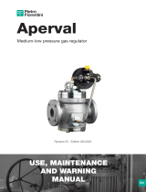
In FIGURE 1 the valve functional diagram is illustrated.
1.1 MAIN SPECIFICATIONS
The PVS 782 valves are safety accessories fit for the use on preliminary treated non
aggressive gaseous fluids.
Such valves may be installed both on pipelines and on pressure vessels.
The main specifications of these valves are:
- Top-entry body fit for the flanged coupling;
- Soft insert on the seat for a better tightness

4
Figure 1

5
Figure 1: setting inspection port
Operating pressure,
Motorization pressure,
Atmospheric pressure
Posit. Noun
(A) Pilot chamber
(B) Main chamber
(C) Pilot chamber
(D) Pilot chamber
(1) Connection pipe
(2) Pilot filter
(3) nozzle
(4) diaphragm
(5) setting spring
(6) valve plug
(7) positioning spring
(8) pilot plug
(9) discharge connection
(10) connection pipe
(11) spring
(12) ring nut
(13) safety diaphragm
(14) rod
(15) spring
1.2 VALVE CONTROL
The PVS 782 valve is a pilot-operated valve therefore the valve opening and closing
operations are controlled by a pilot device.
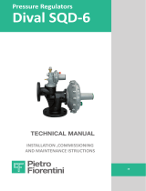
The below listed pilot devices are available:
Pilot P 15/A field of intervention1,5 – 43 bar ( see figure 2 );
Pilot P 16/A field of intervention11,5 – 43 bar (see figure 2 );
Pilot P 17/A field of intervention140 – 70 bar ( see figure 2 );

6
Figure 2

7
1.3 DESCRIPTION OF THE OPERATION
Make reference to figure 1.
Under ordinary conditions the controlled pressure, that is the valve inlet pressure reaches the
pilot chamber (A) and (C) (1) through the connection pipe (1) and the filter (2), and, through
the nozzle (3) it reaches the valve main chamber (B).
On the pilot diaphragm (4) the controlled pressure acts on one side and the load of the
setting spring acts on the other side (5); on the pilot safety diaphragm (14) the controlled
pressure acts on the chamber (C), the spring (16) and the leakage pressure from the
diaphragm, if any (4) ) acts on the chamber (D); on the valve main plug (6) the controlled
pressure and the positioning spring (7) act on the chamber (B) on one side, on the other side
the same pressure, but applied on a smaller section, corresponding to the main diameter of
the valve bore acts. Therefore, contrary to what happens in the traditional spring safety
valves, when the controlled pressure is near the setting pressure, the load applied on the
plug seat increases instead of decreasing thus ensuring a perfect seal also with values very
near to the intervention values.
Until the controlled pressure is lower than the setting value, the spring action (5) prevails on
the value of the fluid thrusts on the diaphragm (4) and the plug-pilot (8) keeps the discharge
connection shut (9).
When instead the pressure reaches the setting value, the plug-pilot (8) opens allowing to
discharge the fluid in the chamber(E) and the consequent full opening of the plug (6)
When the plug-pilot (8) begins to discharge, a flow is formed thus determining a pressure
drop on the orifice (3) and this determines the value of the valve blowdown The equipment is
designed in such a way that in case one of the main components of the valve or of the pilot
device breaks the valve opens; in fact:
a) the breakage of the small connection pipes (1), (10) or of the relevant fittings causes the
emptying of the chamber (B) and therefore the opening of the plug (6).
b) the breakage of the spring (7) does not determine considerable operating variations,
because it only keeps the plug (6) in the closing position when the valve is commissioned.
c) the breakage of the spring (5) determines the opening of the plug-pilot (8) and
therefore the emptying of the chamber (E) and the consequent opening of the plug
(6).

8
d) (valid for P15/A pilot) the breakage of the diaphragm (4) does not damage the
valve operation because the leakage, if any, feeds the chamber (D) that balancing
itself with the ( C) allows the spring (16) to raise the plug-pilot (8) by means of the
rod (15) thus allowing the emptying of the chamber (B).
e) ( valid for P 16/A and P 17/A pilot ) the breakage of the diaphragm (4) does not
damage the valve operation because any leakage through the ‘’piston effect’’ on the
spring support causes the opening of the valve-pilot ( 8 ) and the consequent
opening of the valve plug ( 6 ).
The adjustment of the setting value is made by means of the ring nut (12) inside the
pilot and by using different springs according to the predetermined setting value.
The spring (11) allows the extra stroke of the spring-diaphragm unit without loading
the plug-pilot (8) on its seal seat
1.4 VALVE SIZING
The PVS 782 valve is sized by means of the formula reported on the RACCOLTA E
chapter E. 1. D. that is
q = ( 0,9 x K ) x (394,9 x C ) x P
1
x A x
11
xTZ
M
where:
q = max. flow rate to be discharged in Kg/h
A = min. passage way in cm
2
( see table 1 )
K = flow coefficient ( 0,56 )
P
1
= setting pressure plus 10% (abs. bar)
T
1
= temperature of the fluid at the valve inlet in °K
M = molecular mass of the fluid in Kg/Kmol
Z
1
= compressibility factor of the fluid at the discharge conditions ( = 1 if not known)
C = Coefficient of expansion
( )
( )
( )
1k
1k
1k
2
kC
−
+
+
=

9
k = coefficient of the isentropic equation
Table 1
Dimension 1” 1” ½
2” 2” ½
3” 4” 6” 8”
Area cm
2
5,31 13,85
22,89
35,24
54,08
102,02
203,48 359,50
2. INSTALLATION
2.1 GENERAL WARNINGS
Before the installation , commissioning, or maintenance, the operators shall:
- examine the safety devices applicable to the installation where they have to work
- obtain the necessary authorizations to work, when required
- equip oneself with the necessary individual protections ( helmet, goggles, etc.. )
- make sure that the area where they have to work is equipped with the required collective
protections and with the necessary safety signs.
The handling of the equipment and of its components shall be carried out after evaluating that the
lifting devices are fit for the loads to be lifted ( lifting capacity and functionality ). The handling of
the equipment shall be carried out by using the lifting eyes arranged on the equipment itself .
The use of motorized means is reserved to the personnel in charge of this.
In case the installation of the system and of its accessories requires the application of
compression fittings, these shall be installed by following the instructions of the manufacturer of
the compression fittings. The choice of the compression fittings shall be compatible with the use
specified for the equipment and with the plant specifications, where required.
The commissioning shall be carried out by properly trained personnel.
During the commissioning, non strictly personnel shall be moved away and the prohibition area
shall be properly signaled (signs, barriers, etc…).

10
2.2 GENERAL INSTRUCTIONS
The valve installation shall be carried out in compliance with the prescriptions (laws or regulations)
in force in the place of installation.
In particular the specifications of natural gas plants shall be in compliance with the law provisions
or regulations in force in the place of installation, or at least in compliance with the EN 12186 or
EN12279 regulations (we remind that the installation in compliance with such laws minimizes the
risk of fire hazard).
The valve shall be installed by making sure that the operating pressure of the unit where it is
installed never exceeds the value of the permissible maximum pressure (PS).
The user shall moreover arrange suitable venting or draining system to discharge the pressure
and fluid inside the plant before carrying out any inspection or maintenance operation.
In case the installation specifications require it, the valve may be sealed with lead after having
been adjusted at the required intervention value; lead seals may be carried out at the factory
directly by the manufacturer or on site by the user.
2.3 SPECIAL INSTRUCTIONS
Before installing the valve it is necessary to be sure that :
- the valve may be inserted in the arranged space and it is sufficiently accessible for the following
maintenance operations, dimensions and weights are reported in table 2;
- the upstream and downstream pipelines are at the same level as the inlet and outlet connections
and they can support the weight of the valve;
- the pipeline inlet/outlet flanges are parallel to the valve seal surfaces;
- the inside of the valve is clean and the valve itself was not damaged during the transport;
- the upstream pipeline was cleaned in order to expel residual impurities such welding slag, sand,
varnish waste, water, etc.
Install the valve considering that the flow direction is compulsory and it is showed with an arrow on
the valve body itself.
The valve may be installed both with vertical flow direction and horizontal flow direction.
For the installation please refer to figures 3 and 4.

11
The valves placed upstream from the valve, if any, shall be of a total flow type, so that the
discharge capacity is not limited.
Connect the pilot sensing line by means of compression fittings, according to the plant
specifications.
In case the plant specifications require it, connect the pilot vent to the specific drain pipe.
On the valve drain pipe arrange a protection end against water and nesting
The connections to the inlet and outlet pipelines are carried out by means of standardized flanges
the sizes and types of which are showed on the data plate ( see chapter 2.4 ); the choice of the
connecting screws and of the seal gaskets shall be made by the installer who shall consider such
information and the conditions of use in the place of installation.
Table 2
Note: the dimensions and the weights for S 150 are also valid for the PN 16 version

12
Legend of Figure
Dimensioni d’ingombro: overall dimensions, peso in kg: weight in Kg

13
Figure 3
Not included in our supply,
Discharge to the atmosphere,
Cut-off valve

14
Figure 4

15
2.4 CONDITIONS OF USE
We recommend to check, before commissioning, that the conditions of use are in compliance with
the equipment specifications.
Such specifications are reported on the identification plates of each valve (figure 5).
Figure 5
The meaning of the symbols written on the plate is the following
Safety valve valve model
Cg flow rate coefficient ( where foreseen )
S. n. serial number
PS max. permissible pressure
DN valve nominal diameter
Flange type of flange
TS permissible operating temperature
Who total intervention pressure field
Wao specific intervention pressure field of the inserted spring
Tar. Set-point value ( when applicable )
Date date of test
Pilot type of pilot

16
bpe inlet pressure field
Pemax max inlet pressure
Wh total intervention field
Wa specific intervention pressure field with inserted spring
In particular we would like you to draw your attention to the following specifications:
- PS max. permissible pressure.
- TS design temperature (the minimum and maximum values are shown).
- the inlet and outlet connections class.
Moreover, the user shall check that the used materials and the applied surface treatments, if any,
are compatible with the expected use.
Considering the valve geometric specifications, during the design phase no stresses due to traffic,
wind, or seismic events were taken into consideration; therefore, the user shall take proper
precautions in order to limit the effects of such events on the assembly, when these are expected
3.0 COMMISSIONING
3.1 PRESSURIZATION
After the installation check that the connections to the line are correctly executed and that the
vents and drainages on the plant, if any, are closed.
Slowly pressurize the plant ( or the plant section) by means of the upstream process valve or of
other systems arranged for this and make sure that the pressure is at a value than the valve
setting value
3.2 CONTROL OF THE EXTERNAL TIGHTNESS
The tightness test of the valve connections to the plant shall be carried out according to the
provisions in force in the place of installation.
The external tightness is ensured when coating the element under pressure with a foaming agent,
no bubbles appear

17
3.3 CONTROL OF THE INTERNAL TIGHTNESS
The valve internal tightness may be checked by placing the valve in full close position, keeping
the line pressure upstream from the valve and checking that there is not fluid leaks downstream
from the valve and from the pilot blowdown.
3. 4 COMMISSIONING ( INSTALLATION ACCORDING TO DIAGRAM IN FIG. 3 ).
a) On the data plate check that the required intervention value is within the listed limits ( Wao
value on the plate )
b) Fully tighten the adjusting ring nut of the setting on the pilot
c) make sure that the pressure upstream from the cut-off valve is lower than the intervention value
d) slowly open the cut-off valve
e) check the tightness of all the joints placed under pressure with the previous operation
f) increase the pressure up to the intervention value, slowly unscrew the ring nut until the pilot pipe
starts to discharge the gas.
h) very carefully carry on the previous operation until the valve opening
i) decrease the pressure and check that the pilot valve is close again and their tightness.
3. 5 COMMISSIONING ( INSTALLATION ACCORDING TO DIAGRAM IN FIG.4 )
a) With the same order carry out the operations a, b, c, d, e, of paragraph 3.4
b) Connect the C way of the three-way switch valve ( PUSH ) to a chamber with controlled
pressure
c) stabilize the test pressure in the chamber at the same value as the pressure at the safety valve
inlet
d) actuate the three-way valve by connecting the controlled pressure chamber to the pilot sensing
line.
e) increase the test pressure in the controlled chamber up to the intervention value of the safety
valve
f) with the same order repeat the operations g,h, of the previous paragraph.
g) decrease the pressure and check that the pilot valve is close again and their tightness.
h) restore the three-way valve position in order to connect the chamber to be controlled with the
pilot sensing line.

18
4.0 MAINTENANCE
4.1 GENERAL INSTRUCTIONS
The inspection and maintenance interventions are strictly linked to the type of installation. It is
therefore advisable to perform a preventive maintenance, which periodicity, if not established by
the regulations, is relevant to:
- the quality of the transported fluid;
- the cleanness and preservation state of the pipelines in the plant; in general, after the first start
of the plants, more frequent maintenance services are required because of the poor cleanness
inside the pipelines
It is recommended to periodically check the intervention value of the valve according to the
provisions in force on the place of installation and, depending on the needs, perform a
preventive maintenance of the valve and of its pilot.
The periodical inspections concern also the state of the external surface of the valve. In particular
the surface protections shall be restored ( usually the varnishing) in case they are worn.
Before performing any intervention, make sure that the plant section where you operate has been
upstream and downstream cut-off and that the pressure in the concerned pipeline section has
been discharged.
Moreover, make sure to be have a series of recommended spare parts. The spare parts shall be
Pietro Fiorentini Spa genuine spare parts.
NOTE. The use of non genuine spare parts relieves the manufacturer from any liability.

19
4.2 DISASSEMBLY
For the disassembly no special wrenches are required.
Before carrying out the disassembly, put some reference signs on the elements of the pilot that
connect it to the valve
It is necessary to pay particular attention in order not to damage the valve and the o’rings
seats.
Inspect the state of all rubber parts as far as tightness is concerned and replace the damaged
ones or the ones with a long life. Lubricate the surfaces of the moving elements with a thin
grease layer as showed in paragraph 5.
4.3 REASSEMBLY
Reassemble the parts by referring to the signs put on the parts during the disassembly, so that
all the connections match correctly
5.0 LUBRICATION
The valves are already lubricated during the assembly phase (with the most suitable product for
the operation if it is specified in the order) for the following reasons:
1) ease the components assembly
2) improve maneuverability
3) ease the preservation in case of warehouse storage
During the ordinary operation, it is not necessary to lubricate the valve.
We recommend to lubricate the moving elements during the maintenance operations (plug,… )
and the seals with silicone grease.

20
6.0 STORAGE
The PVS 782 valves do not require specific precautions in case of storage for long periods;
anyway it is recommended to pay attention to:
- keep the valves in the original packing;
- keep the protections applied in the factory on the flanged connections;
- store the rubber parts away from direct sun light, in order to avoid a fast aging;
7.0 SPARE PARTS
For the spare parts please refer to the spare part lists
SR 164 Valve PVS/782
SR 182/1 Pilot P 15, P 15/A
SR 182/2 Pilot P 16, P 16/A
SR 182/3 Pilot P 17, P 17/A
Note: the pilots P 15, P 16 e P 17 are no more manufactured.
When ordering the spare parts, list:
Type of valve
Built-in accessories,
Serial no.
Year of manufacture
Type of fluid used
Part no. (position)
Quantity
/