Page is loading ...

IM-P006-07 CH Issue 11 1
DP143, DP143G, DP143H
and DP163, DP163G, DP163Y
Pilot Operated Pressure Reducing Valves
Installation and Maintenance Instructions
1. Safety information
2. General
product information
3. Installation
4. Commissioning
5. Maintenance
6. Spare parts
7.Faultnding
© Copyright 2013
Printed in the UK
IM-P006-07
CH Issue 11
0060026/11

IM-P006-07 CH Issue 11
2

IM-P006-07 CH Issue 11 3
1. Safety information
Safe operation of these products can only be guaranteed if they are properly
installed, commissioned, used and maintained by qualified personnel (see Section
1.11) in compliance with the operating instructions. General installation and safety
instructions for pipeline and plant construction, as well as the proper use of tools
and safety equipment must also be complied with.
1.1 Intended use
Referring to these Installation and Maintenance Instructions, name-plate and
Technical Information Sheet, check that the product is suitable for the intended
use / application. The products listed below comply with the requirements of the
European Pressure Equipment Directive 97 / 23 / EC and carry the mark when so
required. The products fall within the following Pressure Equipment Directive
categories:
Group 2
Product Gases
DP143 and all derivatives DN15 - DN32 SEP
DN40 - DN80 1
DP163 and all derivatives DN15 - DN32 SEP
DN40 - DN80 1
i) The products have been specically designed for use on steam, air and inert
industrial gases which are in Group 2 of the above mentioned Pressure Equipment
Directive. The products’ use on other uids may be possible but, if this is
contemplated,SpiraxSarcoshouldbecontactedtoconrmthesuitabilityofthe
product for the application being considered.
ii) Check material suitability, pressure and temperature and their maximum and
minimum values. If the maximum operating limits of the product are lower than
thoseofthesysteminwhichitisbeingtted,orifmalfunctionoftheproduct
could result in a dangerous overpressure or overtemperature occurrence, ensure
a safety device is included in the system to prevent such over-limit situations.
iii) Determinethecorrectinstallationsituationanddirectionofuidow.
iv) Spirax Sarco products are not intended to withstand external stresses that may
beinducedbyanysystemtowhichtheyaretted.Itistheresponsibilityofthe
installer to consider these stresses and take adequate precautions to minimise
them.
v) Remove protection covers from all connections and protective lm from all
name-plates, where appropriate, before installation on steam or other high
temperature applications.
1.2 Access
Ensure safe access and if necessary a safe working platform (suitably guarded)
before attempting to work on the product. Arrange suitable lifting gear if required.
1.3 Lighting
Ensure adequate lighting, particularly where detailed or intricate work is required.

IM-P006-07 CH Issue 11
4
1.4 Hazardous liquids or gases in the pipeline
Consider what is in the pipeline or what may have been in the pipeline at some
previous time. Consider: ammable materials, substances hazardous to health,
extremes of temperature.
1.5 Hazardous environment around the product
Consider: explosion risk areas, lack of oxygen (e.g. tanks, pits), dangerous gases,
extremesoftemperature,hotsurfaces,rehazard(e.g.duringwelding),excessive
noise, moving machinery.
1.6 The system
Consider the effect on the complete system of the work proposed. Will any proposed
action (e.g. closing isolation valves, electrical isolation) put any other part of the
system or any personnel at risk?
Dangers might include isolation of vents or protective devices or the rendering
ineffective of controls or alarms. Ensure isolation valves are turned on and off in a
gradual way to avoid system shocks.
1.7 Pressure systems
Ensure that any pressure is isolated and safely vented to atmospheric pressure.
Consider double isolation (double block and bleed) and the locking or labelling of
closed valves. Do not assume that the system has depressurised even when the
pressure gauge indicates zero.
1.8 Temperature
Allow time for temperature to normalise after isolation to avoid danger of burns.
1.9 Tools and consumables
Before starting work ensure that you have suitable tools and /or consumables
available. Use only genuine Spirax Sarco replacement parts.
1.10 Protective clothing
Consider whether you and /or others in the vicinity require any protective clothing to
protect against the hazards of, for example, chemicals, high / low temperature,
radiation, noise, falling objects, and dangers to eyes and face.
1.11 Permits to work
All work must be carried out or be supervised by a suitably competent person.
Installation and operating personnel should be trained in the correct use of the
product according to the Installation and Maintenance Instructions.
Where a formal 'permit to work' system is in force it must be complied with. Where
there is no such system, it is recommended that a responsible person should know
what work is going on and, where necessary, arrange to have an assistant whose
primary responsibility is safety.
Post 'warning notices' if necessary.

IM-P006-07 CH Issue 11 5
1.12 Handling
Manual handling of large and /or heavy products may present a risk of injury. Lifting,
pushing, pulling, carrying or supporting a load by bodily force can cause injury
particularly to the back. You are advised to assess the risks taking into account the
task, the individual, the load and the working environment and use the appropriate
handling method depending on the circumstances of the work being done.
1.13 Residual hazards
In normal use the external surface of the product may be very hot. If used at the
maximum permitted operating conditions the surface temperature of some products
may reach temperatures of 300°C.
Many products are not self-draining. Take due care when dismantling or removing
the product from an installation (refer to 'Maintenance instructions').
1.14 Freezing
Provision must be made to protect products which are not self-draining against
frost damage in environments where they may be exposed to temperatures below
freezing point.
1.15 Disposal
Unless otherwise stated in the Installation and Maintenance Instructions, this product
is recyclable and no ecological hazard is anticipated with its disposal providing due
care is taken.
1.16 Returning products
Customers and stockists are reminded that under EC Health, Safety and Environment
Law, when returning products to Spirax Sarco they must provide information on any
hazards and the precautions to be taken due to contamination residues or mechanical
damage which may present a health, safety or environmental risk. This information
must be provided in writing including Health and Safety data sheets relating to any
substancesidentiedashazardousorpotentiallyhazardous.
Warning
If this product is not used in the manner specified by this IMI, then the
protection provided may be impaired.

IM-P006-07 CH Issue 11
6
2. General product information
These instructions relate to the use of the DP143 (Section 2.1) and DP163 (Section 2.2) pilot
operated pressure reducing valves on steam applications but can be used as a guide when the
valve is used on compressed air applications. The DP143G and DP163G are recommended
for compressed air applications, both having a nitrile seal for the main valve and pilot valve
assemblies. Note: For additional information see the relevant Technical Information Sheet.
2.1 DP143, DP143G and DP143H
Description
The DP143, DP143G and DP143H pilot operated pressure reducing valves have been
manufactured using cast steel.
Available types
DP143 Suitable for steam applications
DP143G Is a soft seal version available for compressed air and inert industrial gases.
Note: It is not recommended for oxygen service.
DP143H Is a high temperature version for use up to 350°C.
Sizes and pipe connections
DN15LC - Low Capacity version, DN15, DN20, DN25, DN32, DN40, DN50 and DN80.
Standard flanges: EN 1092 PN25 and PN40, BS 10 Table 'J' and ASME 300.
Available on request: ASME 150 and JIS 20.

IM-P006-07 CH Issue 11 7
Pressure / temperature limits
The product must not be used in this region.
Use the high temperature DP143H version in this region.
A-D-E Flanged EN 1092 PN40, ASME 300 and BS 10 Table J.
A-B-C Flanged ASME 150.
F-G DP143G limited to 120°C @ 26 bar g.
Note: Two colour coded pressure adjustment springs are available for the following
downstream pressure ranges:
Red 0.2 bar g to 17 bar g
Grey 16.0 bar g to 24 bar g
Body design conditions PN40
Maximum design pressure A-D-E 40 bar g @ 40°C
A-B-C 17.3 bar g @ 40°C
Maximum design temperature 350°C @ 24 bar g
Minimum design temperature 0°C
Maximum upstream pressure for saturated steam service A-D-E 28 bar g
A-B-C 14 bar g
DP143 300°C @ 25 bar g
Maximum operating temperature DP143G 120°C @ 26 bar g
DP143H 350°C @ 24 bar g
Minimum operating temperature 0°C
Note: For lower operating temperatures consult Spirax Sarco.
Maximum differential pressure A-D-E 28 bar
A-B-C 14 bar
Designed for a maximum cold hydraulic test pressure of: 60 bar g
Note: With internals fitted, test pressure must not exceed: 40 bar g
Pressure bar g
Temperature °C
A B
F
Steam
saturation
curve
D
EGC

IM-P006-07 CH Issue 11
8
2.2 DP163, DP163G and DP163H
Description
The DP163, DP163G and DP163Y pilot operated pressure reducing valves have been
manufactured using stainless steel.
Available types
DP163 Suitable for steam applications
DP163G Is a soft seal version available for compressed air and inert industrial gases.
Note: It is not recommended for oxygen service.
DP163Y Having a lower rate pressure control spring is suitable for steriliser/ autoclave applications
Sizes and pipe connections
DN15LC - Low Capacity version, DN15, DN20, DN25, DN32, DN40, DN50 and DN80.
Standard flanges: EN 1092 PN25 and PN40, BS 10 Table 'J' and ASME 300.
Available on request: ASME 150 and JIS 20.

IM-P006-07 CH Issue 11 9
The product must not be used in this region.
A-D-E Flanged EN 1092 PN40, BS 10 Table J and ASME 300.
A- B-C Flanged ASME 150.
F-G DP163G limited to 120°C @ 26 bar g.
Note: Two colour coded pressure adjustment springs are available for the following
downstream pressure ranges:
Red 0.2 bar g to 17 bar g
Grey 16.0 bar g to 21 bar g
Yellow 0.2 bar g to 3.0 bar g (DP163Y only)
Body design conditions PN40
Maximum design pressure A-D-E 36.4 bar g @ 20°C
A-B-C 18.9 bar g @ 20°C
Maximum design temperature 250°C @ 24 bar g
Minimum design temperature -10°C
Maximum upstream pressure for saturated steam service A-D-E 25 bar g
A-B-C 14 bar g
Maximum operating temperature A-D-E 250°C @ 24 bar g
A-B-C 250°C @ 12.1 bar g
Minimum operating temperature 0°C
Note: For lower operating temperatures consult Spirax Sarco.
Maximum differential pressure A-D-E 25 bar
A-B-C 14 bar
Designed for a maximum cold hydraulic test pressure of: 60 bar g
Note: With internals fitted, test pressure must not exceed: 40 bar g
Pressure bar g
Temperature °C
Pressure / temperature limits
A B D
GEC
F
Steam
saturation
curve

IM-P006-07 CH Issue 11
10
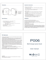
Fig. 1
Balance pipe assembly
Pressure adjustment spring
3. Installation
Note: Before actioning any installation observe the 'Safety information' in Section 1.
3.1 Supply (Figure 1)
The DP143 and DP163 pilot operated pressure reducing valves are supplied ready for fitting.
The pressure adjusted spring will be the one most suitable for the downstream pressure
quoted on the order but will not be pre-set.

IM-P006-07 CH Issue 11 11
Pressure
control
pipe
Strainer with
100 mesh stainless
steel screen
Separator
Steam
supply
Spiratec
sensor
chamber
Float type
steam trap
Pilot operated
pressure
reducing valve
1 m or
15 pipe diameters clear
on either side
Downstream isolating valve to
provide no-load conditions for
setting pressure reducing valve
Safety
valve
Discharge
pipe
Check
valve
Strainer
Fig. 2 Recommended installation
Steam
supply
3.2 Fitting (Figure 2 and Figure 3)
The valve should always be fitted in horizontal pipework with the main diaphragm chamber
below the line. To meet high capacities or widely varying loads, or where stand-by facility
is required, two or more valves may be used in parallel.
Fig. 3
Important DP143 only
Direct injection systems
This product contains a rust inhibitor to
protect it against corrosion during storage.
To avoid any possible contamination of
your product, after first blowing down the
approach pipework, we recommend that
the valve is blown through thoroughly in
order to remove any trace of the inhibitor.
Condensate
Condensate

IM-P006-07 CH Issue 11
12
3.3 Pipeline sizing
The piping on both sides of the valve must be sized so that velocities do not exceed 30 m / sec.
This means that a properly sized valve will often be smaller than the upstream pipework and
invariably the downstream pipework will be larger than the upstream pipework.
3.4 Pipeline stresses
Line stresses such as could be caused by expansion or inadequate support should not be
imposed on the valve body.
3.5 Isolating valves
These should preferably be of the fullway type.
3.6 Removal of condensate
Ensure that the pipework is adequately drained so that the valve is supplied with dry steam.
The ideal arrangement is to fit a separator in the steam supply. If by closing downstream
isolating valves, the downstream pipework is likely to become flooded, a trap set should be
installed to remove condensate forming as a result of radiant losses.
3.7 Preventing dirt
The valve should be protected by a pipeline strainer the same size as the upstream pipework
and fitted with 100 mesh screen. The strainer should be fitted on its side to prevent the
accumulation of water.
3.8 Pressure sensing
For applications that require closer control, improved stability or maximum capacity condition
the balance pipe should be replaced by an external pressure sensing pipe (supplied by others)
as follows:
Remove the balance pipe assembly.
The resulting " BSP tapping in the side of the body should be blanked using the plug provided
in the linen bag attached to the valve (which also contains the fitting instructions). The other
" BSP tapping in the side of the pilot valve chamber, should be blanked off using the plug
fitted in the tapping provided on the front of the pilot valve chamber. Into this latter tapping,
fit the brass compression fitting with brass compression ring which is also contained in the
linen bag. This is suitable for the fitting of 6 mm O/D pipe. If suitable pipe is not available the
compression fitting can be removed and ¼" nominal bore steel pipe screwed directly into the
pilot valve chamber.
The pressure sensing pipe should be connected into the top of the reduced pressure main at
a point where in either direction there is a length of straight pipe uninterrupted by fittings for at
least 1 m or 15 pipe diameters whichever is the greater. It should be arranged with a positive
fall so that any condensate can drain away from the DP valve. Where the size of the reduced
pressure main makes it difficult to maintain a fall when entering the top of the main, the pressure
control pipe may be connected in the side of the main.
3.9 Pressure gauges
It is essential to fit a pressure gauge on the downstream side so that the valve can be properly
set. A pressure gauge on the upstream side is an essential diagnostic tool.

IM-P006-07 CH Issue 11 13
Fig. 4 Setting procedure sequence DP143, DP143G and DP143H
Fig. 5 Setting procedure sequence DP163, DP163G and DP163Y
✽ See Section 3.6, page 9
Condensate
return
Steam flow
Optional bypass line (see Section 3.10)
✽
Condensate
return
Steam flow
Optional bypass line (see Section 3.10)
✽ See Section 3.6, page 9
✽
3.10 Bypass
If it is essential to maintain a constant supply of steam across the valve. It may be necessary
to install a bypass to ensure continuation of supply when the reducing valve is being serviced
Figure 4 and Figure 5.
The bypass valve will normally be the same size as the reducing valve. The handwheel should
be padlocked to prevent unauthorised use, and when in use should be under constant manual
supervision.
The bypass may be arranged above or to the side of the main assembly but never below it.

IM-P006-07 CH Issue 11
14
3.11 Safety valve
A safety valve should be fitted to protect the downstream equipment from excessive pressure.
It should be set to lift below the safe working pressure of the downstream equipment, and will
normally be sized to pass the full capacity of the PRV should the PRV fail in the fully open
position. The safety valve set pressure should take account of its reseat characteristic and the
'No-load' pressure setting of the PRV. For example, the typical blowdown value (reseat
differential) for a DIN type safety valve is 10% of set pressure. The minimum possible safety
valve set pressure must therefore equal the no load set pressure of the reducing valve plus the
blowdown value of the safety valve plus a small margin of at least 0.1 bar. If the set pressure
is any lower, if whatever reason the safety valve lifts it will not shut properly and will simmer,
creating a leak which is often wrongly diagnosed as a result of a leaking reducing valve.
Discharge pipework should be taken to a safe place.
3.12 Position in relation to other control valves
Line or system isolation valves (A), either remotely actuated or manual, should be installed on
the upstream side of the DP reducing valve.
Where there is downstream control equipment (B), particularly when it is fast acting (for instance
pulsed piston actuated valves) ensure the control equipment is at least 50 pipe diameters away
from the DP to prevent pressure pulses being transmitted back causing unstable operation and
premature wear or if this is impractical an intermediate vessel can provide a similar benefit.
Where a safety valve (C) is required to protect the system downstream of a DP and where a
control valve is also being used downstream of the DP, it is recommended that the safety valve
is fitted downstream of the control valve rather than in between the DP and the control valve.
If any slight leakage occurs this will avoid any pressure build-up causing nuisance operation
of the safety valve but provide complete protection for the downstream system.
Where valves are installed downstream of the DP (B) the intermediate downstream pipework
must be properly trapped (D) to ensure no condensate can buil up on the downstream side of
t h e D P.
Fig. 6 The position of the pressure reducing valve in relation to other
control equipment
D
C
B
A
A

IM-P006-07 CH Issue 11 15
4.1 Start-up (Setting the valve)
1. Ensure that all connections are properly made and that all valves are closed.
2. Check that the adjustment is turned fully anticlockwise until the spring is slack.
3. Open small valve in pressure control line.
4. Blow through the approach pipework by removing the cap and screen from the strainer
protecting the steam trap draining the upstream pipework. Replace upon completion.
Do not remove the screen from the main line strainer during this operation. Although this
should remove most of the dirt which is present, it may be necessary to examine and clean
the main line strainer at regular intervals.
5. Slowly open the upstream isolating valve until it is fully open.
6. Using a 19 mm A/F spanner slowly turn the adjustment screw in a clockwise direction
until the desired downstream pressure reading is obtained.
7. Holding the adjustment screw in position with the spanner tighten down the lock-nut to
secure the setting of the adjustment spring, making sure that the 'C' washer stays in
position (Figure 1).
8. Slowly open the downstream valve until it is fully open.
4.2 Two or more valves in parallel
When more than one reducing valve is used it is an advantage to use two valves of unequal
size, the smaller one being chosen to meet the lower load requirements and the larger valve
to come into operation so that both meet the normal and maximum demand.
It is necessary to set each valve independently following the start-up procedure detailed in
Section 4.1 but setting the smaller valve at some 0.1 bar higher than the larger one.
Each valve should be set against dead end conditions achieved by closing a downstream
isolating valve.
4. Commissioning

IM-P006-07 CH Issue 11
16
Fig. 7 24
26
17
18
16
19
19A
29
10
3
12
6
1
2
5
8
7
9
31
11
21
15
13
23
30
25
32
28
5. Maintenance
4
14
20
22
27
Note: Before actioning any maintenance programme observe
the 'Safety information' in Section 1.
Warning:
The body gasket (15) contains a thin stainless steel support ring which may cause
physical injury if not handled and disposed of correctly.

IM-P006-07 CH Issue 11 17
Warning - DP163
The 316 type stainless steel used in the construction of the DP163 product,
particularly for screwed or close fitting parts, is very susceptible to galling or cold
welding. This is an inherent characteristic of this type of material and great care
should therefore be taken when dismantling or reassembling.
If the application permits it is recommended that a light smear of a PTFE based
grease is applied to any mating parts before reassembly.
5.1 Routine maintenance
It is recommended that the valve is dismantled once every 12 to 18 months for a complete
overhaul and ideally this should be carried out with the valve removed from the line.
The parts that may require replacing or refurbishing are listed below:
- Main valve (17) and main valve seat (18)
- Pilot valve assembly (13)
- Pilot diaphragms (9)
- Main diaphragms (23)
A detailed procedure for servicing the above items is described in Sections 5.3 to 5.9.
In addition to the above items the pushrod (26) liner bush, and control pipework and fittings
should be cleaned of any scale deposit if necessary.
5.2 Diaphragms and cleaning
If the valve is dismantled and either the main diaphragms or the pilot diaphragm are
not renewed care must be taken not to turn the diaphragms over - refit them in exactly
the same position as when dismantled. The control orifices in the adaptors of the control
pipe assembly (27) as well as the balance pipe (19 or 19A) must be kept clear of dirt.
Blow through with compressed air if necessary - do not use a drill on the control orifices,
as enlargement of the orifices might upset the operation of the valve.
Main diaphragms used in the DP143 and DP163 reducing valves
Size of valve Diaphragm diameter
DN15, DN15 LC, DN20 125 mm
DN25, DN32 166 mm
DN40, DN50 230 mm
DN80 300 mm
5.3 Pressure adjustment springs and ranges
Three colour coded adjustment springs are available for the following reduced pressure ranges:
Red 0.2 to 17 bar
Grey DP143 16.0 to 24 bar
DP163 16.0 to 21 bar
Yellow DP163Y 0.2 to 3 bar

IM-P006-07 CH Issue 11
18
5.4 How to renew or change the control spring
It is not necessary to isolate the valve in order to change the spring.
1. Release the lock-nut (2) and turn the adjustment screw (1) anticlockwise until the spring
is slack.
2. Slide out the 'C' washer (3) from underneath the lock-nut and remove the cover (12).
3. Remove the old spring (6) and replace it with a new one remembering to replace the top
spring plate (5).
4. Replace the cover and 'C' washer, and turn the adjustment screw clockwise until the desired
pressure reading is obtained.
5. Holding the adjustment screw in position tighten down the lock-nut making sure the
'C' washer stays in position.
5.5 How to renew the pilot valve assembly and bellows seal
1. Isolate the reducing valve and zero the pressure.
2. Release the lock-nut (2) and turn the adjustment screw (1) anticlockwise until the spring
is slack.
3. Slide out the 'C' washer (3) from underneath the lock-nut and remove the cover (12).
4. Remove the spring (6) and top spring plate (5).
5. Undo the 4 x M10 nuts (8) and remove the spring housing (4), bottom spring plate (7) and
the diaphragms (9).
6. Undo the pipework union nuts and release the 6 mm stainless steel pipework.
7. Undo the nuts (21) and remove the pilot valve housing (10) making sure that the main valve
spring (16) is still positioned correctly on top of the main valve head (17).
8. Unscrew the pilot valve assembly (13) which includes the integral strainer screen (14) by
using a 27 mm A/F socket and also remove the plunger (11).
9. Unscrew the bellows seal assembly (31) using a 24 mm A/F socket. If necessary this
bellows seal assembly can be replaced.
10. With the bellows seal still removed screw in the new pilot valve assembly (13) and tighten
down to a torque of 115 N m.
11. Insert the plunger (11) in from the top and check that there is a gap of 0.7 mm between
the top of the plunger and a straight edge placed across the diaphragm location recess
(See Figure 8).
Note: Because of production tolerances the plunger is supplied slightly longer than is
always required and it will generally be necessary to grind or machine material off the top
end to give the correct length. After machining make sure the sharp edges are removed
from the top of the plunger as these could damage the bellows. The 0.7 mm gap (see
previous Step 11) ensures that with the bellows seal fitted there is just a slight gap between
it and the diaphragm whilst in its neutral position.
12. After locating the bellows seal assembly carefully over the plunger and tighten down to
a torque of 115 N m.
13. Check with straight edge again, that with the top of the bellows pressed lightly onto the top
of the plunger, there is a slight clearance - a mere line of light between the straight edge
and the top of the bellows (see Figure 8).
14. Before reassembling the valve make sure that the gasket faces on both the pilot valve block
and the body are clean and that the main valve spring (16) is positioned correctly on top of
the main valve head.

IM-P006-07 CH Issue 11 19
15. Fit new gasket (15) and secure the pilot valve block assembly onto the body with the
nuts (11). Tighten these nuts to the torques shown in Table 1.
16. Refit the 6 mm stainless steel pipework and retighten the union nuts to ensure a steam
tight seal.
17. Refit the two diaphragms (9) making sure that they are fitted the same way round as they
were removed and that all contact surfaces are clean. If necessary two new diaphragms
can be fitted.
18. Place the bottom spring plate (7) in position and secure the spring housing with the
4 x M10 nuts (8) tightening to a torque of 50 N m.
19. Replace the spring (6) and the top spring plate (5) turning the adjustment screw (1) until it
just locates on the top spring plate. Replace the cover (12) and the 'C' washer (3).
20. Bring the valve back into commission by following as many steps as are necessary in
Section 4.1, 'Start-up'.
Table 1
Recommended tightening torques for the pilot valve block securing nuts item (21)
Size of valve Nut size Tightening torque
DN15LC, DN15 and DN20 M10 40 N m
DN25 to DN50 M12 60 N m
Note: for DN40 and DN50 valves predating 1996:- M16 110 N m
DN80 M12 80 N m
5.6 How to clean the pilot valve strainer screen
1. Isolate the reducing valve and zero the pressure.
2. Release the lock-nut (2) and turn the adjustment screw (1) anticlockwise until the spring
is slack.
3. Undo the union nuts and release the 6 mm stainless steel pipework.
4. Undo the nuts (21) and remove the pilot valve housing (10) complete with the spring
housing assembly, making sure that the main valve spring (16) is positioned correctly
on top of the main valve head (17).
Fig. 8
0.7 mm
(0.028")
Straight edge Straight edge

IM-P006-07 CH Issue 11
20
5. Holding the pilot valve block upside down, unscrew the screen retaining nut using a
27 mm A/F spanner.
6. Remove the screen (14) for cleaning, taking care not to lose the small return spring (13D)
and ball (13C) which can also be cleaned if necessary.
7. Refit the ball, spring and screen and refit the screen retaining nut (13B), tightening it to
a torque of 15 N m.
8. Make sure that the gasket faces on both the pilot valve block and the body are clean.
Make sure that the main valve spring (16) is positioned correctly on top of the main valve
head (17).
9. Fit new gasket (15) and secure the pilot valve block assembly onto the body with the
nuts (21). Tighten these nuts to the torque shown in Table 1.
10. Refit the 6 mm stainless steel pipework and retighten the union nuts to ensure a steam
tight seal.
11. Bring the valve back into commission by following as many steps are as necessary in
Section 4.1, 'Start-up'.
11
14
13C
13D
13A
13B
Fig. 9
5.7 How to renew the pilot valve diaphragms
1. Isolate the reducing valve and zero the pressure.
2. Release the lock-nut (2) and turn the adjustment screw (1) anticlockwise until the spring
is slack.
3. Slide the 'C' washer (3) from underneath the lock-nut and remove the cover (12).
4. Remove the spring (6) and the top spring plate (5).
5. Undo the 4 x M10 nuts (8) and remove the spring housing (4), bottom spring plate (7) and
the old diaphragms (9).
6. Refit 2 new diaphragms (9) making sure that all contact faces are clean.
7. Place the bottom spring plate (7) in position and secure the spring housing with the
4 x M10 nuts (8) tightening to a torque of 50 N m.
8. Replace the spring (6) and top spring plate (5), turn the adjustment screw (1) until it just
locates on the top spring plate. Replace cover (12) and 'C' washer (3).
9. Bring the valve back into commission by following as many steps as are necessary in
Section 4.1, 'Start-up'.
/