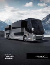
PREVOST H3-45 Owner's manual

Category
Cars
Type
Owner's manual

This manual is also suitable for

i
TABLE OF CONTENTS
FOREWORD........................................................iii
SAFETY PRECAUTIONS ...................................iv
COACH EXTERIOR .........................................1-1
Engine compartment rear door.........................1-3
Engine compartment R.H. side door ................1-3
Main power compartment .................................1-4
Wheelchair lift door............................................1-4
Baggage compartments....................................1-4
Fuel filler door.................................................... 1-4
A/C condenser door..........................................1-4
Entrance door....................................................1-5
Rear-view mirrors..............................................1-5
Reclining bumper compartment........................1-7
HVAC compartment..........................................1-7
Rear electric compartment................................1-7
Engine radiator door.......................................... 1-8
Retractable back-up camera.............................1-8
110-120 volt in-station connector......................1-8
COACH INTERIOR........................................... 2-1
DRIVER'S AREA...............................................2-1
Entrance door....................................................2-1
Destination signs............................................... 2-1
Driver's personal compartment.........................2-1
Ashtray...............................................................2-1
Cigarette lighter.................................................2-2
Adjustable HVAC registers ...............................2-2
Driver's power window ...................................... 2-2
Sun visors (blinds).............................................2-2
Inside mirrors.....................................................2-2
Safety Belt .........................................................2-2
Driver's seat.......................................................2-3
Tour guide seat..................................................2-5
Microphone jacks ..............................................2-5
PASSENGERS' AREA......................................2-6
Passenger seats................................................2-6
Swivel seats.......................................................2-6
Exits...................................................................2-6
Ventilation hatch................................................2-6
Adjustable air registers......................................2-7
Stop/service chime............................................2-7
Reading lamp ....................................................2-7
Sun visor (blind).................................................2-7
Folding trays......................................................2-8
Waste container ................................................2-8
Card tables ........................................................2-8
Quick-lounge .....................................................2-8
Galley................................................................. 2-9
Lavatory.............................................................2-9
CONTROLS & INSTRUMENTS.......................3-1
KEYS..................................................................3-1
DRIVER'S AREA ...............................................3-2
L.H. CONTROL PANEL.....................................3-3
Transmission display.........................................3-3
Cruise control.....................................................3-3
Driver's power window switch............................3-4
Mirror controls....................................................3-4
Tag axle control valve........................................3-4
Parking brakes control valve .............................3-5
Water heater timer.............................................3-5
Low buoy control valve......................................3-5
Parking brakes override valve...........................3-5
Diagnostic data reader (DDR) receptacle.........3-5
Steering wheel adjustment unlock air valve......3-6
Dashboard compartments.................................3-6
Rear-view TV monitor........................................3-6
Cigarette lighter..................................................3-6
Ashtray...............................................................3-6
Utility compartment............................................3-6
DASHBOARD....................................................3-7
Control switches.................................................3-8
Trip data recorder (TDR).................................3-12
Telltale panel....................................................3-12
Gauges.............................................................3-16
Vehicle height...................................................3-17
Front door buttons............................................3-17
Control head.....................................................3-17
Radio................................................................3-18
HVAC control unit ............................................3-18
Brightness control............................................3-19
Ignition switch...................................................3-19
Air registers......................................................3-19
STEERING COLUMN CONTROLS................3-26
Transmission output retarder ..........................3-20
Multifunction lever............................................3-20
Horns................................................................3-21
FOOT-OPERATED CONTROLS....................3-21
Service brakes .................................................3-21
Acceleratior pedal............................................3-22
Steering wheel adjustment unlock air valve....3-22
MANUAL TRANSMISSION.............................3-29
SEMI-AUTOMATIC TRANSMISSION............3-23
AUTOMATIC TRANSMISSION.......................3-23
OTHER FEATURES..........................................4-1
Detroit Diesel Electronic Control System .........4-1
Detroit Diesel Data Hub.....................................4-2
Trip Record Access (TRAC)..............................4-2
DDEC IV electronic control module (ECM).......4-4
Water heater ......................................................4-5
TABLE OF CONTENTS
ii
Trip Data Recorder (TDR).................................4-6
World Transmission (WT) electronic controls 4-10
Jacobs engine brake.......................................4-11
Transmission retarder.....................................4-11
Antilock Braking System (ABS) ......................4-11
Kneeling system..............................................4-12
High-buoy........................................................4-12
Low-buoy ........................................................4-12
Retractable tag axle ........................................4-12
Tag load release system (TLR) ......................4-13
Safety lights.....................................................4-13
Back-up alarm .................................................4-13
Hubdometer.....................................................4-13
Mud flaps and splash guards..........................4-14
Spare parts kit .................................................4-14
STARTING AND STOPPING
PROCEDURES.................................................5-1
Starting engine from driver's compartment.......5-1
Starting engine from engine compartment.......5-1
Cold weather starting ........................................ 5-2
Engine block heater...........................................5-2
Engine warm-up................................................ 5-2
World Transmission (WT) warm-up..................5-3
Jump starting.....................................................5-3
EMERGENCY SAFETY FEATURES .............. 6-1
Emergency exits................................................6-1
Front door emergency opening.........................6-2
Safety equipment ..............................................6-2
Air system..........................................................6-3
Emergency and parking brakes........................6-4
Alarm system.....................................................6-5
CARE AND MAINTENANCE...........................7-1
Interior cleaning.................................................7-1
Exterior cleaning................................................7-2
Oil level verification............................................7-3
Coolant level check...........................................7-6
Air tanks.............................................................7-7
Fire extinguishers..............................................7-7
Water separator.................................................7-7
110-120 Volt in station lighting circuit...............7-8
110-120 Volt connector.....................................7-8
Belt tension adjustment.....................................7-8
Back-up camera................................................7-9
Filter restriction indicator...................................7-9
Air filters..............................................................7-9
Lavatory maintenance .....................................7-10
Flexible hose inspection ..................................7-11
Pre-starting inspection.....................................7-11
Changing wheels .............................................7-12
Towing..............................................................7-14
Lubrication........................................................7-14
First service on new coach..............................7-14
Daily inspection................................................7-14
General recommendations..............................7-16
TECHNICAL INFORMATION...........................8-1
Dimensions ........................................................8-1
Weights ..............................................................8-1
Storage volume..................................................8-1
Seats ..................................................................8-1
Capacities ..........................................................8-2
Fuel type.............................................................8-2
Wheels and tires................................................8-2
Belts....................................................................8-2
Transmission......................................................8-3
Drive axle ratio...................................................8-3
Alignment ...........................................................8-3
Brakes................................................................8-4
Steering..............................................................8-4
Suspension ........................................................8-4
Electrical system................................................8-4
Sound system....................................................8-4
Video system .....................................................8-4
Oil specifications................................................8-4
Heating and air conditioning system.................8-5
Antilock Braking System (ABS).........................8-5
Water heater technical data...............................8-6
DDEC IV diagnostic codes................................8-6
World Transmission (WT) diagnostic codes.....8-9
Eaton Fuller semi-automatic transmission
fault codes........................................................8-25
Light bulb data..................................................8-26
Data plates and certifications ..........................8-28
ANNEX
SERVICE LITERATURE......................................1
NOTICE.................................................................2
INDEX ...................................................................3
iii
FOREWORD
The H3-41 and H3-45 are the current generation
of highway coaches produced by Prevost Car
Incorporated. Prevost Car Incorporated is
committed to the continuous improvement of
coach quality, reliability, durability and safety.
With innovative features, the H3 series coach was
designed with passenger and driver safety and
comfort in mind.
This manual contains information available at the
time of publication. Because optional equipment
is covered in this manual, some of the optional
equipment described may not apply to your
coach. If in doubt, refer to the technical
documentation package provided with the coach.
Driver's controls and instruments incorporate
advanced technology for enhanced driving ease
and security. This manual describes the main
features, instruments and controls, and servicing
requirements for both standard and optional
equipment. Read this manual carefully to take
advantage of the coach's advanced features and
to insure optimum safety and passenger comfort.
Keep this manual with the coach at all times.
Make sure this manual is kept with the coach
when ownership is transferred. Please notify
Prevost Car Incorporated soon after any change
of address or transfer of ownership. This will
ensure we provide prompt and reliable coach
service to all coach operators. Use the
appropriate card at the end of this manual.
Warnings, cautions and notes are used
throughout this manual to emphasize important
points when necessary.
WARNINGS call attention to instructions which
must be precisely followed to avoid injury to
persons.
CAUTIONS call attention to instructions which
must be followed to avoid damage to equipment.
NOTES provide supplemental information and
call attention to instructions which make the job
easier.
The service life of the coach depends on the kind
of attention it receives. Pay close attention to the
warnings, cautions and notes. Read the various
notices and instructions posted throughout the
coach and attached to equipment.
Since continuous improvement is a primary focus
at Prevost Car Incorporated, we reserve the right
to make changes anytime, without notice, and
without incurring any obligation.
Before reproducing or copying this manual, in
whole or in part, written consent must be
obtained from Prevost Car Incorporated.
iv
SAFETY PRECAUTIONS
To ensure safe and reliable operation, take note
of the safety precautions as follows:
a) Operation and maintenance of the coach
must be performed only by qualified
personnel.
b) Use caution when embarking and
disembarking passengers.
c) Always pay attention to pedestrians passing
in front and behind the coach. Always yield
to pedestrians at pedestrian walkways.
d) Inspect the coach before operating.
e) Make sure good visibility is maintained at all
times. Keep windshields clean and free of
obstructions.
f) Make sure all doors are closed and secure
before operating the coach. Before driving,
conduct a walkaround inspection to check
for security of all baggage compartment
doors and equipment access doors.
g) Adjust the driver's seat so that all controls
can be reached easily.
h) Always wear the safety belt when driving.
i) Check the instrument panel frequently. Do
not operate the coach when dials or
indicators are not in the normal operating
condition.
j) Switch from high beams to low beams when
meeting or following other vehicles within
500 feet (150 meters).
k) Do not drive over obstacles on the road.
Empty cartons, piles of leaves, and
snowdrifts could conceal hidden dangers
that could damage the coach suspension
and underbody.
l) When turning or changing lanes, signal your
intention well in advance.
m) When approaching to make a right turn,
reduce the space between the coach and
the curb to make sure another vehicle
cannot pass on the right. Since the coach
makes wide turns, allow enough space to
make safe turns.
n) Never leave the coach unattended with the
engine running, or with the key in the
ignition. Turn off the engine, remove keys
and apply the parking brake before leaving
the coach.
o) The service life of the coach depends on the
kind of maintenance it receives. Always
record any problems and report them
immediately to maintenance personnel.
p) Shut-off the engine before fueling, adding oil
or performing maintenance or servicing
tasks, unless stated otherwise.
q) Do not run the engine or HVAC system with
access doors left open. Close compartment
doors before operating any equipment.
r) Do not remove the surge tank filler cap or
the cooling system pressure cap when the
engine is hot. Let the engine cool down
before removing filler caps.
s) Fuel is highly flammable and explosive. Do
not smoke when refueling. Keep away from
open flames or sparks.
t) Do not attempt to push- or pull-start a coach
equipped with an automatic transmission.
To avoid damaging gears or bearings in
manual transmission-equipped coaches, do
not push-, pull- or roll-start in first or reverse
gears.
u) For additional information about safe driving
practices, contact the local department of
motor vehicles authority.
Defensive driving
a) To keep the coach from drifting across lanes
during highway driving, always look over the
horizon on the road ahead.
b) Don't stare at the road ahead. Keep your
eyes moving. Check all mirrors and
dashboard instruments frequently.
c) Establish eye-to-eye contact with other
drivers and with pedestrians. Use
headlights, high-beams and low-beams, turn
signals and horn as needed.
d) For city driving, allow a four to six second
travel interval between the coach and the
vehicle ahead. Increase this travel interval
to six to eight seconds for highway driving.
Use increased travel interval for night driving
and in bad weather.
e) Adjust your speed according to the road
conditions, traffic and visibility. Never
exceed the posted speed limits.
SAFETY PRECAUTIONS
v
f) Reduce your speed if another vehicle is
following too close behind to let the vehicle
pass.
g) Be prepared to stop when approaching an
intersection. The stopping distance of the
coach increases with the weight and speed
of the coach.
h) For additional information about defensive
driving practices, contact the local
department of motor vehicles authority.
1-1
CHAPTER 1 : COACH EXTERIOR
H3-45 COACH
H3-45 EXTERIOR VUE 18302
1- Engine Compartment Rear Door..............1-3
2- Engine Compartment R.H. Side Door......1-3
3- Main Power Compartment........................1-4
4- Wheelchair Lift door..................................1-4
5- Baggage Compartment.............................1-4
6- Fuel Filler Door.......................................... 1-4
7- A/C Condenser Door.................................1-4
8- Entrance Door Operating Switch..............1-5
9- Entrance Door...........................................1-5
10- Rear-View Mirrors......................................1-5
11- Reclining Bumper Compartment...............1-7
12- Front Electric & Service Compartment.....1-7
13- Heating, Ventilating and Air Conditioning
Compartment (HVAC)...............................1-7
14- Rear Electric Compartment......................1-7
15- Engine Radiator Door...............................1-8
16- Retractable Back-Up Camera...................1-8
17- 110 - 120 Volt Connector ..........................1-8
COACH EXTERIOR
1-2
H3-41 COACH
H3-41 EXTERIOR VUE 18303
1- Engine Compartment Rear Door..............1-3
2- Engine Compartment R.H. Side Door......1-3
3- Main Power Compartment........................1-4
4- Wheelchair Lift Door..................................1-4
5- Baggage Compartment.............................1-4
6- Fuel Filler Door.......................................... 1-4
7- A/C Condenser Door.................................1-4
8- Entrance Door Operating Switch..............1-5
9- Entrance Door...........................................1-5
10- Rear-View Mirrors......................................1-5
11- Reclining Bumper Compartment...............1-7
12- Front Electric & Service Compartment.....1-7
13- Heating, Ventilating and Air Conditioning
Compartment (HVAC)...............................1-7
14- Rear Electric Compartment......................1-7
15- Engine Radiator Door...............................1-8
16- Retractable Back-Up Camera...................1-8
17- 110 -120 Volt Connector ...........................1-8
COACH EXTERIOR
1-3
ENGINE COMPARTMENT REAR
DOOR
ENGINE
Provides access to the following:
• Engine starting selector;
• Engine coolant surge tank;
• Air cleaner restriction indicator;
• Engine oil dipstick;
• Engine oil reserve tank;
• Automatic transmission oil dipstick;
• Cleaning cabinet connector;
• Fresh water reservoir connector.
The door latch release lever is located in the
upper rear section of the engine compartment
R.H. side door. Push up release lever, then place
hand on the upper right of the rear door and pull
rearward. The door will open automatically.
Always engage the safety catch when the
compartment door is open. Release the catch
before closing the door.
The lighting in the engine compartment turns on
automatically when the door is opened. If the
door is open, an indicator light will illuminate on
the central dashboard.
Warning : Pressurized cylinders assist the rear
engine door opening. To avoid injury when
opening it, do not stand at the rear of the coach.
Stand clear when opening the rear door.
Warning : Do not run engine when the
compartment door is open. Close the engine
compartment door before starting the engine.
ENGINE COMPARTMENT R.H.
SIDE DOOR
DOOR HANDLE
DOOR LATCH RELEASE LEVER
Provides access to the following:
• Engine compartment rear door release lever;
• Fuel filter/water separator (if applicable);
• Power steering fluid reservoir;
• Wet (main) air tank drain valve;
• External air supply fill valve;
• Cold weather starting fluid cup;
• Sump tank filler cap;
• A/C Compressor.
This door can be locked/unlocked using the
exterior compartment key. Lift up the protector
cover to gain access to the lock. Pull up the door
handle to release the latch, then pull the door
open. To keep the door open, engage the safety
COACH EXTERIOR
1-4
catch on top of the door. Release the safety
catch before closing the door.
The lighting in the engine compartment turns on
automatically when the door is opened. If the
compartment door is open, an indicator light will
illuminate on the central dashboard.
Warning : Do not run the engine when the
compartment door is open. Close engine
compartment door before starting engine.
MAIN POWER COMPARTMENT
Provides access to the following:
• Battery voltage equalizer;
• Battery voltage equalizer monitor;
• volt batteries;
• Main breakers for the 12 volt and 24 volt
electrical systems;
• Main power cut-off relay;
• Booster posts.
This door can be locked/unlocked using the
exterior compartment key. Turn the key in the
lock to remove.
The lighting in the compartment turns on
automatically when the door is opened. If the
door is open, an indicator light will illuminate on
the central dashboard.
WHEELCHAIR LIFT DOOR
For proper wheel chair lift operation, refer to the
wheel chair lift manual provided in the technical
publication box of the vehicle. The wheel chair
lift is controlled by a toggle switch located on the
dashboard. Refer to "Controls/Instruments"
chapter (page 3-11).
BAGGAGE COMPARTMENTS
The baggage compartment doors can be
locked/unlocked using the exterior compartment
key. Lift up the cover to gain access to the lock.
Pull up door handle to release the latch, then pull
the door open. Refer to the illustration under
"Engine Compartment R.H. Side Door" in this
chapter. Pressurized cylinders assist the opening
and closing of the doors and hold the doors open.
The lighting in the compartment turns on
automatically when the compartment door is
opened. If the door is open, an indicator light will
illuminate on the central dashboard.
Warning : To avoid injury, keep hands clear of
door edge and door frame when closing
Note : To prevent theft and vandalism, always
lock the baggage compartment doors before
leaving the coach unattended.
Note : The baggage compartment doors can
be locked/unlocked from the driver's position by
an optional central locking system on the L.H.
control panel. Refer to "Controls & Instruments"
chapter (page 3-10).
FUEL FILLER DOOR
Both fuel filler doors can be locked/unlocked
using the exterior compartment key. Turn the key
in the lock to remove.
Note : The L.H. side door lock must be in the
unlocked position before closing.
A/C CONDENSER DOOR
Pull the release latch, located inside the adjacent
baggage compartment to partly open the
condenser door. Push on the Safety hook,
accessible through the opening, to open the door.
COACH EXTERIOR
1-5
Caution : Close baggage compartment door in
order to open condenser door completely.
CONDENSER DOOR
ENTRANCE DOOR
The entrance door can be locked/unlocked with
the exterior compartment key. It can be
locked/unlocked from the inside by a spring-return
lever on the door.
SPRING-RETURN LEVER OEH3B118
Inside Operating Switch
Opening and closing the door is controlled by 2
push buttons located on the R.H. dashboard.
Press and hold the red button to open the door
and the green button to close the door.
Outside Operating Switch
The door must be unlocked before using the
outside operating switch. Opening and closing
the door is controlled by a 3-position toggle switch
located at the left of the entrance door. Push and
hold switch forward to open the door and
rearward to close it.
OUTSIDE OPERATING SWITCH
Door Operation Logic
Operating The Door Using The
Exterior Switch Or The Interior Push-
Buttons
If the switch is held in position until the door is
fully open or closed, the system holds pressure in
the door cylinder, locking the door in that position.
The door can be opened in any position by
releasing the switch or button when the desired
door position is attained.
When the door is not fully open or fully closed, the
system does not maintain pressure in the door
cylinder therefore the door is not locked in
position.
A proximity sensor has the door sealed shut when
it senses the door is almost closed. This works
even when the door is moved manually.
Emergency Door Opening
Refer to "Emergency safety features" chapter
(page 6-2).
REAR-VIEW MIRRORS
The coach is equipped with flat-type and convex-
type rear-view mirrors. Convex mirrors give a
wide angle view. Objects viewed in convex-type
rear-view mirrors appear smaller and are actually
closer than they appear.
To provide good visibility in cold weather, the
mirrors are equipped with heating elements that
are activated by a rocker switch located on the
dashboard. Refer to "Controls & Instruments"
chapter (page 3-4). Thermostats are used to
COACH EXTERIOR
1-6
prevent continuous operation of the heating
elements.
Caution : Do not attach stick-on type convex
mirror accessories to the heated mirror glass.
This could impede uniform heat distribution on the
mirror surface which could break the mirror.
Electrically Adjusted Mirror (Ramco
and Spartan)
Electrically-adjusted mirrors are adjusted by the
outside mirror controls located on the L.H. control
panel. Refer to "Controls & Instruments" chapter
(page 3-4).
Manual adjustment is also possible.
Manual Adjustment
Adjust the side-view mirrors until the side of the
coach is visible. Adjust the flat-type mirror until
the highway is in full view.
Manually Adjusted Mirror
(Spartan)
MIRRORS ADJUSTMENT SCREWS OEH3B120
Horizontal And Vertical Adjustment
Loosen the two Allen screws at the rear of the
mirror body. Adjust the mirror to the desired
angle, then tighten the screws.
Vertical Adjustment
Loosen the hexagonal head screw at the rear of
the mirror body. Adjust the mirror to the desired
angle, then tighten screw.
SCREW
SCREW
SUPPORT
GASKET SUPPORT
BEARING
GASKET
&
RING
ARM
LOWER
COLLAR
CABLE
ASSY
SPARTAN REAR-VIEW MIRRORS 18202
Caution : Do not over tighten the screws.
Tighten until snug.
Manually Adjusted Mirror
(Ramco)
FL
A
T
MI
R
R
O
R
CONVE
X
MI
R
R
O
R
CONVE
X
MI
R
R
O
R
B
A
LL CUP
H
A
LF
CENTE
R
LINE
OF
A
R
M
SC
R
EW
SETSC
R
EWS
MI
R
R
O
R
A
R
M
MOUNTING
BOLT
MOUNTING
B
R
A
CKET
B
A
LL
STEM
MI
R
R
O
R
HE
A
D
POSITION B
A
LL CUP
H
A
LVES SO THE JOINT
BETWEEN THEM LIES ON THE
CENTE
R
LINE OF THE A
R
M.
ENSU
R
ETH
A
TTHESETSC
R
EWS
A
R
ENOTONTHEJOINTBETWEE
N
T
H
E
C
U
P
H
A
L
V
E
S
.
RAMCO REAR-VIEW MIRRORS 18201
Adjustment
Loosen the bolt on the bracket of the mirror body.
Adjust the mirror to the desired angle then tighten
bolt.
Head Mirror Adjustment
Loosen the fixing screws. Adjust the head of the
mirror then tighten fixing screws.
Caution : Do not over tighten the screws.
Tighten until snug.
COACH EXTERIOR
1-7
RECLINING BUMPER
COMPARTMENT
The spare wheel and tire assembly is stored in
the reclining bumper compartment.
Warning : This compartment is not designed for
storage. Never store loose objects in this
compartment since they can interfere with the
steering linkage mechanism.
To access the reclining bumper compartment,
loosen the two retaining nuts located under the
front bumper about 10 turns using the wheel nut
wrench. Push the nuts upward and tilt the front
bumper forward.
FRONT BUMPER
Warning : Since the bumper is heavy, two
people are required to tilt the bumper forward.
To fully lower the bumper, disconnect the safety
hook on the retaining chain on the R.H. side of
the bumper.
When closing the bumper compartment, make
sure to connect the safety hook. Make sure that
the bumper is securely installed and both nuts are
tightened.
FRONT ELECTRIC & SERVICE
COMPARTMENT
Provides access to the following:
• Alarm junction box;
• Front junction box;
• In-station lighting connector;
• Entrance door emergency opening valve;
• Windshield washer reservoir;
• Accessory air tank drain valve;
• External air supply fill valve;
• Spare tire support and rail extension
assembly.
The front service compartment door can be
locked/unlocked with the exterior compartment
key. Lift protector cover to access the lock. Pull
up door handle to release the latch then pull the
door open. Refer to the illustration in "Engine
Compartment R.H. Side door".
The lighting in the front service compartment
turns on automatically when the door is opened.
HVAC COMPARTMENT
The HVAC (Heating, Ventilating and Air-
Conditioning) humidistat control is found in this
compartment.
HVAC COMPARTMENT ACCESS
The compartment door release latch is located
on the left side of the baggage compartment and
to the right of the HVAC compartment door. Pull
the release latch then pull the HVAC
compartment door open
REAR ELECTRIC
COMPARTMENT
Provides access to the following:
• Rear junction box
• Electronic Control Unit (ECU)
• Vehicle Interface Module (VIM)
• Water heater system
COACH EXTERIOR
1-8
The rear electric compartment door can be
locked/unlocked using the exterior compartment
key. Turn the key in the compartment door lock
to remove.
The lighting in the compartment turns on
automatically when the door is opened. If the
door is open, an indicator light on the central
dashboard will illuminate.
ENGINE RADIATOR DOOR
Open the radiator door by pushing down the
release latch.
RADIATOR DOOR
RETRACTABLE BACK-UP
CAMERA
An optional back-up camera is available which
provides the driver with visual assistance when
backing-up. The back-up camera is mounted in a
retractable housing. The camera is automatically
activated when the transmission is put in reverse
gear and the ignition switch is "ON". The TV
monitor is mounted on the top of the dashboard.
Refer to "Controls & Instruments" chapter (page
3-6).
Note : A switch located in the rear electric
compartment is used to retract the back-up
camera for cleaning or maintenance.
110-120 VOLT CONNECTOR
This connector is used with a 110-120 volt supply.
It is connected to the engine block heater and the
optional fresh water tank heater. Refer to "Care
and Maintenance" chapter (page 7-8).
2-1
CHAPTER 2 : COACH INTERIOR
DRIVER'S AREA
Entrance Door
Open and close the entrance door using the
push-button switches located on the dashboard.
Refer to "Controls & Instruments" chapter (page
3-17). In an emergency, an opening valve is also
provided to open the door. Refer to "Emergency
safety features" chapter (page 6-2).
Electrical Destination Sign
Turn the optional destination sign lighting on and
off using the rocker switch located on the
dashboard. Refer to "Controls & Instruments"
chapter (page 3-9).
Depress the selector switch until the desired
destination appears in the sight glass and is
aligned with the arrow.
DESTINATION SIGN UNIT OEH3B210
Note : Use the servo control switch to change
the speed of the destination sign. Use high
speed to search for the desired destination and
slow speed to align the arrow in the sight glass.
Electronic Destination Sign
To change the destination, depress the selecting
switches until the desired destination appears in
the Liquid Crystal Display.
ELECTRONIC DESTINATION SIGN 2EH3B210
Note : The destination sign must be
programmed with a computer connected to the
RS-232 connector prior to first use. Follow the
instructions on the computer disk to install and
run the software.
Driver's Personal Compartment
The driver's personal compartment is located to
the left of the stairway when entering the coach.
The compartment can be locked/unlocked using
the appropriate key. A tour optional guide seat
may be installed in front of the driver’s personal
compartment. The seat is secured using
securing devices.
PERSONAL COMPARTMENT
Ashtray
To open the ashtray, push slightly on lid's side.
Remove ashtray by pulling out.
COACH INTERIOR
2-2
Warning : To prevent fire, never put paper or
plastic wrappers in the ashtray. Empty ashtray
often.
Cigarette Lighter
The cigarette lighter is located below the ashtray.
Push lighter in to activate. When ready to use, it
will spring out automatically. Replace lighter in
non-activated position. The cigarette lighter
socket can be used to power 12 volt appliances
(e.g., flashlight, vacuum cleaner). The maximum
power consumption for appliances plugged in this
socket is 130 watts. Make sure the appliances
are equipped with suitable plugs that will not
damage the socket.
Note : The cigarette lighter can be used after the
ignition key has been removed.
Adjustable HVAC Registers
The HVAC system has adjustable registers to
control air flow. They are located on the
dashboard, refer to "Controls & Instruments"
chapter (page 3-19). The direction and volume of
air flow are adjustable.
Driver's Power Window
The driver's area is equipped with a power
window. The power window is controlled by using
the rocker switch located on the L.H. side control
panel. Refer to "Controls & Instruments" chapter
(page 3-4).
Sun Shades (Blinds)
Raising and lowering of the front blinds is
controlled by two 3-position rocker switches
located on the dashboard. Refer to "Controls &
Instruments" chapter (page 3-9).
The driver is protected from side glare by a
spring-release type blind on the left window.
The optional Plexiglas partition, located behind
the
driver, may also be equipped with the same blind.
Pull down and release the blind in the desired
position. To raise the blind, depress the
unlocking lever.
DRIVER’S LEFT WINDOW BLIND OEH3B214
Inside Mirrors
Two mirrors are located in the driver's area. The
left overhead mirror provides visibility in the
critical area on the R.H. side of the coach. Adjust
the left overhead mirror to see through the front
passenger windows. The central mirror allows
the driver to see passengers in the aisle.
Safety Belt
The driver's seat and the optional tour guide seat
are equipped with retractable safety belts. To
fasten safety belt, pull latch plate slowly and insert
into the buckle until it locks (clicks). The inertia
reel is self-adjusting. Manual adjustment is not
required.
FASTENING SAFETY BELT OEH3B222
COACH INTERIOR
2-3
Immediately report problems with safety belts to
maintenance personnel.
Note : The safety belt must be pulled out slowly
and steadily, otherwise the inertia reel will lock
before the latch plate reaches the buckle. If the
inertia reel locks, let the belt retract completely
before trying again.
Warning : To prevent serious injury during
sudden braking or accidents, make sure the lap
belt is snug and positioned low on the hips. Make
sure the belt is not twisted. Check the belt and
belt hardware. It should be free of damage.
Report problems with safety belts to maintenance
personnel.
Warning : To avoid pinching fingers between
the retractor and control knobs, move safety belt
retractor before adjusting seat angle.
Caution : Do not let the belt rub against edges.
Do not bleach or dry clean.
To unfasten the safety belt, press the red button
in the center of the buckle and allow the belt to
retract. If the belt does not retract, pull it out and
check for kinks or twists. Make sure that the belt
remains untwisted as it retracts.
UNFASTENING SAFETY BELT OEH3B218
Driver's Seat
The coach is equipped with a ISRI seat which is
offered in three models. The standard model
(model 6000) has mechanical suspension. The
optional models (models 6500 and 6801) are
equipped with air suspension. All seat models
come equipped with safety belts. Adjustable
armrests and lumbar supports are also available.
Warning: The driver's seat must be adjusted
within easy reach of controls. Never adjust the
seat while the coach is moving.
Warning : Always wear safety belt. Make sure
the seat is adjusted and safety belt is fastened
before driving.
DRIVER’S SEAT ADJUSTMENT (MECHANICAL)
OEH3B220
Driver's Seat Adjustment
ARMREST
The driver's seat can be
equipped with two folding
armrests which can be raised or
lowered for convenience.
To adjust the armrest to a
different position, turn the
control
knob (1) counterclockwise about 12 turns
without applying pressure on the armrest, push
the armrest to desired position. Lock in position
by turning the control knob clockwise.
Note : Armrest may be raised at all times from
its locked position simply by pulling up.
COACH INTERIOR
2-4
BACKREST
Lift lever (2) then adjust backrest
to desired angle.
TILT (front)
To lower or raise the seat's front
section, pull handle (3) up and
push or pull the seat cushion.
TILT (rear)
To lower or raise the seat's rear
section, pull handle (4) up and
push or pull the seat cushion.
UP AND DOWN
Pull both handles (3 and 4) up to
adjust height of the seat.
FORE-AND-AFT
To adjust distance between
driver and dashboard, pull
handle (5) up and slide the seat
forward or backward.
Note : Fore-and-aft seat adjustment control may
also be located at the front of the seat.
SUSPENSION
For maximum mechanical
suspension performance, rotate
handwheel (6) until your body
weight (in pounds) is shown on
the indicator.
The seat suspension resistance can be changed
to suit the driver. Turn handwheel clockwise to
increase suspension resistance and counter-
clockwise to decrease resistance.
Note : Air suspension seats self-adjust to the
driver's weight. There is no handwheel
suspension adjustment.
LUMBAR SUPPORT
To inflate the upper lumbar
support bellows, depress the
front rocker switch (7) upward.
To deflate, depress the rocker
switch downward.
Follow the same procedure to inflate and deflate
the lower bellows using the rear rocker switch.
HEADREST
The headrest can be adjusted
forward, rearward and vertically
by 2 inches (50 mm). Directly
move headrest to desired
position.
Warning : For best protection, position headrest
behind your head, not behind your neck.
COACH INTERIOR
2-5
Driver's Pneumatic Seat
PNEUMATIC SUSPENSION SEAT 18126A
ARMREST
Rotate the control knob (1) to
select desired arm resting angle.
When not in use, raise armrest
parallel with backrest.
BACKREST
Lift lever (2) to select proper
adjustment angle of backrest.
FORE-AND-AFT
Pull handle (3) up and slide seat
forwards or backwards to adjust
distance between driver and
dashboard.
Warning : The driver's seat must be adjusted
within easy reach of controls. Never adjust the
seat while the coach is moving.
TILT
Pull handle (4) up, and push
down or pull up on front of seat
cushion to tilt the seat.
SUSPENSION
For maximum suspension
performance, push down on knob
(5) until required weight is
reached.
UP AND DOWN
Press on "+" or "-" (6) to raise or
lower driver’s seat.
LUMBAR SUPPORT
Push on upper section of rocker
switch (7) to inflate lumbar
support bellows inside the seat
backrest. Push on lower section
of rocker switches to deflate
bellows.
Note : Rear and front rocker switches are
respectively for upper and lower lumbar support
bellows.
Tour Guide Seat
TOUR GUIDE SEAT OEH3B222
The optional folding tour guide seat is equipped
with a retractable arm rest and safety belt. The
seat can be folded up for convenience when
embarking and disembarking passengers.
The tour guide seat can be removed and stored in
the driver's personal compartment. To remove
the seat from the stairwell wall, unscrew and
COACH INTERIOR
2-6
remove the two anchoring pins and washers at
the bottom of the seat assembly. Raise and
unhook the seat assembly.
Warning : Make sure tour guide's safety belt is
buckled up prior to departure.
Microphone Jacks
Six microphone jacks for the PA system are
available in the following locations:
• On the side wall of the L.H. control panel;
• On the R.H. side of the dashboard;
• One optional outlet for the tour guide on
each of the modesty panels;
• One optional outlet on the lavatory wall,
behind the last row of seats;
• One optional outlet under the parcel rack, at
the rear of the coach.
PASSENGERS' AREA
Passenger Seats
Passenger seats may be equipped with grip
handles, ashtrays, newspaper holders, trays and
footrests.
PASSENGER SEATS EQUIPMENT OEH3B226
All seats are track-mounted so that the seating
configuration can be changed. Each seat is
mounted on oval aluminum pedestals to make it
easier to clean between the pedestal and side
wall.
Passenger seat backrests can be tilted by using
the push-button located on the side of the seat
cushion. Depress and hold push-button, then
adjust backrest to the desired angle. Release
push-button to lock backrest in position. The
hydraulic seat back adjustment mechanism is
equipped with a pull-off spring.
A folding armrest is installed on the aisle side of
the passenger Another folding armrest is located
between the two seats and can be raised for
passenger convenience. A fixed armrest is
installed on the window side of the seat.
Swivel Seats
The coach is equipped with two sets of swivel
seats to allow installation of card tables. The
swivel seat can be rotated for passenger privacy.
To rotate seats, unscrew the wing nut from under
each seat cushion then remove cushions.
Remove the four wing screws, pull seats toward
the aisle and rotate the seat counter-clockwise.
Align mounting holes, secure with wing screws
and install seat cushions.
Note : Instructions for making swivel seat
adjustments are affixed on the rear frame under
the seat cushion.
Exits
Three windows on each side of the coach, along
with the ventilation hatch(es), can be opened from
inside for emergency egress. There is a fourth
emergency window on the L.H. side of H3-45
coaches. Refer to "Emergency Safety Features"
chapter (page 6-1).
Ventilation Hatch
A ventilation hatch is installed in the ceiling at the
rear of the coach. A second, optional hatch can
be installed in the ceiling at the front of the coach.
To open the hatch, push up with both hands and
pull down to close. The ventilation hatch can be
completely removed for emergency egress.
Refer to "Emergency Safety Features" chapter
(page 6-1).
Warning : Be aware of coach overhead
clearance when traveling under overpasses with
the ventilation hatch(es) open. Check for
maximum clearance height.
Adjustable Air Registers
Adjustable registers located under the parcel
racks provide air flow to the passengers. Air flow
can be directed by rotating the nozzle. To adjust
air flow volume, open or close the flaps..
Passengers can orient individual registers and
regulate airflow. Activation of parcel rack fans is
  • Page 1 1
  • Page 2 2
  • Page 3 3
  • Page 4 4
  • Page 5 5
  • Page 6 6
  • Page 7 7
  • Page 8 8
  • Page 9 9
  • Page 10 10
  • Page 11 11
  • Page 12 12
  • Page 13 13
  • Page 14 14
  • Page 15 15
  • Page 16 16
  • Page 17 17
  • Page 18 18
  • Page 19 19
  • Page 20 20
  • Page 21 21
  • Page 22 22
  • Page 23 23
  • Page 24 24
  • Page 25 25
  • Page 26 26
  • Page 27 27
  • Page 28 28
  • Page 29 29
  • Page 30 30
  • Page 31 31
  • Page 32 32
  • Page 33 33
  • Page 34 34
  • Page 35 35
  • Page 36 36
  • Page 37 37
  • Page 38 38
  • Page 39 39
  • Page 40 40
  • Page 41 41
  • Page 42 42
  • Page 43 43
  • Page 44 44
  • Page 45 45
  • Page 46 46
  • Page 47 47
  • Page 48 48
  • Page 49 49
  • Page 50 50
  • Page 51 51
  • Page 52 52
  • Page 53 53
  • Page 54 54
  • Page 55 55
  • Page 56 56
  • Page 57 57
  • Page 58 58
  • Page 59 59
  • Page 60 60
  • Page 61 61
  • Page 62 62
  • Page 63 63
  • Page 64 64
  • Page 65 65
  • Page 66 66
  • Page 67 67
  • Page 68 68
  • Page 69 69
  • Page 70 70
  • Page 71 71
  • Page 72 72
  • Page 73 73
  • Page 74 74
  • Page 75 75
  • Page 76 76
  • Page 77 77
  • Page 78 78
  • Page 79 79
  • Page 80 80
  • Page 81 81
  • Page 82 82
  • Page 83 83
  • Page 84 84
  • Page 85 85
  • Page 86 86
  • Page 87 87
  • Page 88 88
  • Page 89 89
  • Page 90 90
  • Page 91 91
  • Page 92 92
  • Page 93 93
  • Page 94 94
  • Page 95 95
  • Page 96 96
  • Page 97 97
  • Page 98 98
  • Page 99 99
  • Page 100 100
  • Page 101 101
  • Page 102 102
  • Page 103 103
  • Page 104 104
  • Page 105 105
  • Page 106 106
  • Page 107 107
  • Page 108 108
  • Page 109 109
  • Page 110 110
  • Page 111 111
  • Page 112 112
  • Page 113 113
  • Page 114 114
  • Page 115 115
  • Page 116 116
  • Page 117 117
  • Page 118 118
  • Page 119 119
  • Page 120 120
  • Page 121 121
  • Page 122 122

PREVOST H3-45 Owner's manual

Category
Cars
Type
Owner's manual
This manual is also suitable for

Ask a question and I''ll find the answer in the document

Finding information in a document is now easier with AI