Carlisle Air Regulator 535 555 Owner's manual

Type
Owner's manual

This manual is also suitable for

SB-6-162-R1 (5/2018) 1 / 4 www.carlisleft.com
Replace- Ind
Ref. ment Parts
No. Part No. Description Req.
1 KK-4940 Cap 1
2 KK-4139-3 Repair Kit 1
3 O-Ring
4 Spring 1
5 Disc. Stem Assembly
6 Diaphragm Assembly
7 Spring 1
8 KK-4138 Spring Cage and 1
Handle Kit
9 Spring Depressor 1
10 Spring Cage
11 Lock Nut
12 Handle
A
Y
X
PARTS LIST
Figure 2
HAR-502 HAR-505 HAR-535 HAR-555
Locations
Inlet A A A A
Outlet
Main Line B X X, Y
Regulated X, Y B, X, Y B, Y• B
Thread Sizes
1/4 NPT(F) A, B, X, Y A, B, X, Y X, Y X, Y
3/8 NPT(F) A, B A
1/2 NPT(F) B
This "Y" port has restricted flow for gauge use
only.
To avoid a blast of air when installing or
removing regulator, always turn off air
supply and bleed off air in the tank by
turning the air relief valve thumb screw
counterclockwise. Wait until all the air has
escaped before removing regulator.
INSTALLATION
Before installing, blow out pipe line to remove
scale and other foreign matter. This unit has dry seal
pipe threads; use pipe compound or tape sparingly
on male threads only. Install regulator so that air
will flow in direction of arrow stamped on body;
install as near as possible to equipment serviced.
DESCRIPTION
HAR Regulators provide regulation of air pressure
from the incoming air supply to the point of use.
See Figure 1 for port information.
SPECIFICATIONS
Regulated Pressure Range 0-125 psi
Maximum Input Pressure 250 psi
Capacity 40 scfm
Maximum Operating Temperature 120°F
Figure 1
Handle
B
*Government NSN No. 4410-00-430-4158 = HAR-555
2
5
6
3
7
4
8
10
9
11
12
1
EN
SERVICE MANUAL
HAR-535 AND HAR-555
*
AIR REGULATORS
EN
SB-6-162-R1 (5/2018)2 / 4www.carlisleft.com
ACCESSORY ITEMS
Gauges
Part Pressure Range Thread
No. (psi) Size
GA-73 0-30 1/4" NPT(M)
GA-288 0-160 1/4" NPT(M)
83-2727 0-100 1/4" NPT(M)
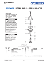
OPERATION
To change adjustment, loosen lock nut (11). Turn
handle (12) clockwise to increase the regulated pres-
sure and counterclockwise to lower pressure. This
is a relieving-type regulator; therefore, the reduced
pressure follows adjustment of the handle.
To lock adjustment, screw the lock nut (11) down until
it stops against the spring cage. Tighten lock nut (11)
with a wrench.
PARTS REPLACEMENT
Refer to the PARTS LIST for numbers that contain the
desired replacement parts. Replacement parts are
sold only through kits. Use the kit part number and
description when ordering replacement parts.
PREVENTIVE MAINTENANCE
Cleaning:
Note
To clean, it is not necessary to remove regula-
tor from line. Refer to Figure 2 as a guide in
reassembly.
Never use carbon tetrachloride, trichloroeth-
ylene, thinner, acetone or similar solvents in
cleaning parts.
To clean, depressurize regulator and disassemble.
Clean parts with denatured alcohol and blow out body
with compressed air.
When reassembling, make sure the disc stem (5) fits
into the center hole of the diaphragm assembly (6).
Tighten spring cage (10) slightly more than handtight
to 45 in. lbs. torque.
To avoid a blast of air when installing or
removing regulator, always turn off air sup-
ply and bleed off air in the tank by turning
the air relief valve thumb screw counter-
clockwise. Wait until all the air has escaped
before removing regulator.
If the air supply is kept clean, the regulator should
provide long periods of uninterrupted service.
Erratic regulator operation or loss of regulation is
normally due to dirt in the disc area.
H-2008 Hex Nipple, 1/4" NPT(M) x 1/4"
NPS(M) - Used at inlet/outlet connections
for convenient hook-up.
CA PROP
65
PROP 65 WARNING
WARNING: This product contains chemicals
known to the State of California to cause cancer
and birth defects or other reproductive harm.
EN
SB-6-162-R1 (5/2018) 3 / 4 www.carlisleft.com
NOTES
EN
SB-6-162-R1 (5/2018)4 / 4www.carlisleft.com
WARRANTY POLICY
This product is covered by Carlisle Fluid Technologies’ materials and workmanship limited warranty.
The use of any parts or accessories, from a source other than Carlisle Fluid Technologies,
will void all warranties. Failure to reasonably follow any maintenance guidance provided
may invalidate any warranty.
For specic warranty information please contact Carlisle Fluid Technologies.
For technical assistance or to locate an authorized distributor,
contact one of our international sales and customer support locations.
Region Industrial/Automotive Automotive Renishing
Americas
Tel: 1-800-992-4657 Tel: 1-800-445-3988
Fax: 1-888-246-5732 Fax: 1-800-445-6643
Europe, Africa,
Middle East, India
Tel: +44 (0)1202 571 111
Fax: +44 (0)1202 573 488
China
Tel: +8621-3373 0108
Fax: +8621-3373 0308
Japan
Tel: +81 45 785 6421
Fax: +81 45 785 6517
Australia
Tel: +61 (0) 2 8525 7555
Fax: +61 (0) 2 8525 7575
Carlisle Fluid Technologies is a global leader in innovative nishing technologies.
Carlisle Fluid Technologies reserves the right to modify equipment specications without prior notice.
DeVilbiss
®
, Ransburg
®
, ms
®
, BGK
®
, and Binks
®
are registered trademarks of Carlisle Fluid Technologies, Inc.
©2018 Carlisle Fluid Technologies, Inc.
All rights reserved.
For the latest information about our products, visit www.carlisleft.com
  • Page 1 1
  • Page 2 2
  • Page 3 3
  • Page 4 4

Carlisle Air Regulator 535 555 Owner's manual

Type
Owner's manual
This manual is also suitable for

Ask a question and I''ll find the answer in the document

Finding information in a document is now easier with AI