Page is loading ...

ZT-2000 DIO SERIES
UserManual
Warranty
All products manufactured by ICP DAS are under warranty
regarding defective materials for a period of one year, beginning
from the date of delivery to the original purchaser.
Warning
ICP DAS assumes no liability for any damage resulting from the use
of this product. ICP DAS reserves the right to change this manual
at any time without notice. The information furnished by ICP DAS
is believed to be accurate and reliable. However, no responsibility
is assumed by ICP DAS for its use, nor for any infringements of
patents or other rights of third parties resulting from its use.
Copyright
Copyright © 2013 by ICP DAS. All rights are reserved.
Trademarks
Names are used for identification purposes only and may be
registered trademarks of their respective companies.
TechnologySupport
If you have any problems, please feel free to contact us
via email at [email protected]
.
ICPDAS,ZT‐2000DIOSEIRESUserManual,Version1.1.0Page1
Copyright©2013byICPDASCo.,Ltd.AllRightsReserved.

ICPDAS,ZT‐2000DIOSEIRESUserManual,Version1.1.0Page2
Copyright©2013byICPDASCo.,Ltd.AllRightsReserved.
TableofContents
1Introduction...................................... 6
1.1 ................................ 6IntroductiontoZigBee
1.2 ............... 7IntroductiontotheZT‐2000DIOSeries
2InformationtotheHardware....................... 8
2.1 ......................................... 8Specifications
................................. 8SpecificationstoZigBee
............ 8SpecificationstoZT‐2000SeriesModuleBoard
............................ 9SpecificationstotheZT‐2042
........................... 10SpecificationstotheZT‐2043
........................... 11SpecificationstotheZT‐2052
........................... 12SpecificationstotheZT‐2053
........................... 13SpecificationstotheZT‐2060
2.2 ....................................... 14PinAssignments
.......................... 14PinAssignmentstotheZT‐2042
.......................... 15PinAssignmentstotheZT‐2043
.......................... 16PinAssignmentstotheZT‐2052
.......................... 17PinAssignmentstotheZT‐2053
.......................... 18PinAssignmentstotheZT‐2060
2.3 ......................................... 19BlockDiagram
............................ 19BlockDiagramtotheZT‐2042
............................ 19BlockDiagramtotheZT‐2043
............................ 20BlockDiagramtotheZT‐2052
............................ 20BlockDiagramtotheZT‐2053
............................ 21BlockDiagramtotheZT‐2060
2.4 ...................................... 22WireConnections
......................... 22WireConnectionstotheZT‐2042
......................... 22WireConnectionstotheZT‐2043
......................... 23WireConnectionstotheZT‐2052
......................... 23WireConnectionstotheZT‐2053
......................... 24WireConnectionstotheZT‐2060

ICPDAS,ZT‐2000DIOSEIRESUserManual,Version1.1.0Page3
Copyright©2013byICPDASCo.,Ltd.AllRightsReserved.
3SettinguptheZT‐2000DIODevice................ 25
3.1 ........ 25IntroductiontotheConfigurationParameters
3.2 ......... 26IntroductiontotheRotationandDIPSwitch
3.3 ...................... 28StartingtheZT‐2000I/ODevice
3.4 .............................................. 29Examples
3.5 ............................... 30CommunicationsTesting
4DCON/ModbusRTUCommandSet...................... 31
4.1 .......... 31HowtocommunicatewithZT‐2000I/ODevice
4.2 ............................ 31DCONProtocolCommandSet
4.2.1 ............................................. 32Checksum
4.2.2 ..................... 33OverviewtheDCONCommandSets
4.2.3 .......................................... 34%AANNTTCCFF
4.2.4 .................................................. 35#**
4.2.5 .......................................... 36#AA00(Data)
4.2.6 .......................................... 38#AA0A(Data)
4.2.7 .......................................... 40#AA1c(Data)
4.2.8 .......................................... 42#AAAc(Data)
4.2.9 ................................................. 43#AAN
4.2.10 ............................................... 44$AA2
4.2.11 ............................................... 45$AA4
4.2.12 ............................................... 47$AA5
4.2.13 ............................................... 48$AA6
4.2.14 ............................................... 49$AAC
4.2.15 .............................................. 50$AACN
4.2.16 ............................................... 51$AAF
4.2.17 .............................................. 52$AALS
4.2.18 ............................................... 54$AAM
4.2.19 ............................................... 55$AAP
4.2.20 ................................................. 56@AA
4.2.21 .......................................... 57@AA(Data)
4.2.22 ............................................... 58~AAD
4.2.23 ............................................. 59~AADVV
4.2.24 ................................................. 60~**
4.2.25 ............................................... 61~AA0
4.2.26 ............................................... 63~AA1
4.2.27 ............................................... 64~AA2
4.2.28 ............................................ 65~AA3EVV
4.2.29 .............................................. 66~AA4V
4.2.30 .............................................. 67~AA5V

ICPDAS,ZT‐2000DIOSEIRESUserManual,Version1.1.0Page4
Copyright©2013byICPDASCo.,Ltd.AllRightsReserved.
4.3 ................. 69TheModbusRTUProtocolCommandSet
4.3.1 .............................. 70ModbusAddressMapping
4.3.2 ................................. 72PLCAddressMapping
4.3.3 ............................ 7301(0x01)ReadtheCoils
4.3.4 ..................... 7602(0x02)ReadDiscreteInputs
4.3.5 .................. 7803(0x03)ReadMultipleRegisters
4.3.6 ............ 8004(0x04)ReadMultipleInputRegisters
4.3.7 ...................... 8205(0x05)WriteaSingleCoil
4.3.8 ................. 8506(0x06)WriteMultipleRegisters
4.3.9 ....................... 8715(0x0F)Writemultiplecoils
4.3.10 ......... 8970(0x46)Read/WritetheModuleSettings
5Troubleshooting................................. 102
6Appendix........................................ 103
6.1 ................................ 103DualWatchdogOperation
6.2 ........................................... 104ResetStatus
6.3 ......................................... 105DigitalOutput
6.4 .................................. 106LatchedDigitalInput
6.5 ..................................... 107LEDDisplayStatus
................................................ 107ZT‐2042
................................................ 108ZT‐2043
................................................ 108ZT‐2052
................................................ 108ZT‐2053
................................................ 108ZT‐2060
6.6 .................. 109TheExtensiontotheSoftwareAddress

ICPDAS,ZT‐2000DIOSEIRESUserManual,Version1.1.0Page5
Copyright©2013byICPDASCo.,Ltd.AllRightsReserved.
What’sintheShippingPackage?
The shipping package contains the following items:
MoreInformation
ANT‐124‐05
ZT‐2000DIOModule
QuickStart
If any of these items are missing or damaged, please contact your local distributor
for more information. Save the shipping materials and cartons in case you need to
ship the module in the future.
Documentation:
CD: \Napdos\ZigBee\ZT_Series\Document
http://ftp.icpdas.com/pub/cd/usbcd/napdos/zigbee/zt_series/document
Software:
CD: \Napdos\ZigBee\ZT_Series\Utility
http://ftp.icpdas.com/pub/cd/usbcd/napdos/zigbee/zt_series/utility

ICPDAS,ZT‐2000DIOSEIRESUserManual,Version1.1.0Page6
Copyright©2013byICPDASCo.,Ltd.AllRightsReserved.
1
Introduction
1.1 IntroductiontoZigBee
ZigBee is a specification for a suite of high-level communication protocols
using small, low-power digital radios based on the IEEE 802.15.4 standard for
personal area networks. ZigBee devices are often used in mesh network form to
transmit data over longer distances, passing data through intermediate devices
to reach more distant ones. This allows ZigBee networks to be formed ad-hoc,
with no centralized control or high-power transmitter/receiver able to reach all of
the devices. Any ZigBee device can be tasked with running the network.
ZigBee is targeted at applications that require a low data rate, long battery
life, and secure networking. ZigBee has a defined rate of 250 kbit/s, best suited
for periodic or intermittent data transmission or a single signal transmission from
a sensor or input device. Applications include wireless light switches, electrical
meters with in-home-displays, traffic management systems, and other
consumer and industrial equipment that requires short-range wireless transfer
of data at relatively low rates. The technology defined by the ZigBee specification
is intended to be simpler and less expensive than other WPANs.

ICPDAS,ZT‐2000DIOSEIRESUserManual,Version1.1.0Page7
Copyright©2013byICPDASCo.,Ltd.AllRightsReserved.
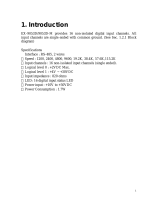
1.2 IntroductiontotheZT‐2000DIOSeries
ZT-2000 I/O series devices are small wireless ZigBee I/O modules based on
the IEEE802.15.4 standard that allow data acqusition and control via personal
area ZigBee networks. They provide digital input/output, timer/counter and
other functions. These modules can be remotely controlled using a set of DCON
or Modbus RTU commands. The DIO modules support TTL signals,
photo-isolated digital input, relay contact output, solid-state relay output,
PhotoMOS output and open-collector output. See Sec. 2.1 for more detailed
information.
ZT-2000 I/O series is a wireless data acquisition-based client/server system.
Accordingly, a Net Server for the ZigBee (ZT-2570/ZT-2550) is essential in such
systems. So, if there is any configuration issue of ZigBee coordinator, please
refer to the “ZT-25XX ZigBee Converter Quick Start“ document for more
information, which can be found at the following link:
http://ftp.icpdas.com/pub/cd/usbcd/napdos/zigbee/zt_series/document/

2
InformationtotheHardware
2.1 Specifications
SpecificationstoZigBee
Wireless
RF Channels 16
RF Transmit Power 11 dBm
Antenna (2.4 GHz) 5 dBi Omni-directional Antenna
Transmit Range (LOS) 700 m (Typical)
Max. Slaves Supported 255
EMI Certification CE/FCC, FCC ID
SpecificationstoZT‐2000SeriesModuleBoard
Gernal
Protocols Supports DCON and Modbus RTU Protocols
Hot Swap Rotary and DIP switch
Mechanical
Flammability Fire Retardant Materials (UL94-V0 Level)
Dimensions (W x L x H) 33 mm x 87 mm x 107 mm
Installation DIN-Rail
Environment
Operating Temperature -25 to 75 °C
Storage Temperature -30 to 80 °C
Relative Humidity 10 ~ 90% RH, Non-condensing
ICPDAS,ZT‐2000DIOSEIRESUserManual,Version1.1.0Page8
Copyright©2013byICPDASCo.,Ltd.AllRightsReserved.

SpecificationstotheZT‐2042
Relay Output
Output Channels 4
Output Type PhotoMOS Relay, Form A
Load Voltage 60 V
DC
/ V
AC
60 V/1.0 A Operating Temperature: -25 °C ~ +40 °C
60 V/0.8 A Operating Temperature: +40 °C ~ +60 °C
Max. Load Current
60 V/0.7 A Operating Temperature: +60 °C ~ +75 °C
Power-on Time 5.0 ms
Power-off Time 0.5 ms
Digital Output
Output Channels 4 (Sink)
Output Type Isolated Open Collector
Max. Load Current 700 mA/channel
Load Voltage +5 V
DC
~ +50 V
DC
External Power Reversed Protection
and Short Circuit Protection
Yes
Current Limited Protection 1.1 A
Intra-module Isolation, Field to Logic 3000 V
DC
ESD Protection +/-4 kV Contact for each Channel
Gernal
PWR 1 Red LED, ZigBee Device Power Indicator
ZigBee 1 Green LED, ZigBee Communication Indicator
LED Indicator
DO0 ~ DO7 8 Red LED, Digital Output Channel Indicators
Power
Power consumption 0.88W (Max.)
※Please see other specifications to the “Specifications to ZigBee” and
“Specifications to ZT-2000 Series Module Board” topics at the section 2.1.
ICPDAS,ZT‐2000DIOSEIRESUserManual,Version1.1.0Page9
Copyright©2013byICPDASCo.,Ltd.AllRightsReserved.

SpecificationstotheZT‐2043
Digital Output
Output Channels 14 (Sink)
Output Type Isolated Open Collector
Max. Load Current 700 mA/channel
Load Voltage +5 V
DC
~ +50 V
DC
External Power Reversed Protection
and Short Circuit Protection
Yes
Current Limited Protection 1.1 A
Intra-module Isolation, Field to Logic 3750 V
DC
ESD Protection +/-4 kV Contact for each Channel
Gernal
PWR 1 Red LED, ZigBee Device Power Indicator
ZigBee 1 Green LED, ZigBee Communication Indicator
LED Indicator
DO0 ~ DO13 14 Green LED, Digital Output Channel Indicators
Power
Power consumption 0.88W (Max.)
※Please see other specifications to the “Specifications to ZigBee” and
“Specifications to ZT-2000 Series Module Board” topics at the section 2.1.
ICPDAS,ZT‐2000DIOSEIRESUserManual,Version1.1.0Page10
Copyright©2013byICPDASCo.,Ltd.AllRightsReserved.

SpecificationstotheZT‐2052
Digital Input
Input Channels 8
ON Voltage Level: +3.5 V
DC
~ +30 V
DC
Wet Contact (Sink/Source)
OFF Voltage Level: +1 V
DC
Max.
Input Impedance 3 kΩ, 0.33 W
Channels: 8
Max. Count: 16-bit (65535)
Max. Input Frequency: 100 Hz
Counter
Min. Pulse Width: 5 ms
Intra-module Isolation, Field to Logic 3750 V
DC
ESD Protection +/-4 kV Contact for each Channel
Gernal
PWR 1 Red LED, ZigBee Device Power Indicator
ZigBee 1 Green LED, ZigBee Communication Indicator
LED Indicator
DI0 ~ DI7 8 Green LED, Digital Input Channel Indicators
Power
Power consumption 1 W (Max.)
※Please see other specifications to the “Specifications to ZigBee” and
“Specifications to ZT-2000 Series Module Board” topics at the section 2.1.
ICPDAS,ZT‐2000DIOSEIRESUserManual,Version1.1.0Page11
Copyright©2013byICPDASCo.,Ltd.AllRightsReserved.

SpecificationstotheZT‐2053
Digital Input
Input Channels 14
ON Voltage Level: Close to GND
OFF Voltage Level: Open
Dry Contact (Sink)
Effective Distance for Dry Contact: 500 m Max.
ON Voltage Level: +3.5 V
DC
~ +30 V
DC
Wet Contact (Sink/Source)
OFF Voltage Level: +1 V
DC
Max.
Input Impedance 3 kΩ, 0.33 W
Channels: 14
Max. Count: 16-bit (65535)
Max. Input Frequency: 100 Hz
Counter
Min. Pulse Width: 5 ms
Intra-module Isolation, Field to Logic 3750 V
DC
ESD Protection +/-4 kV Contact for each Channel
Gernal
PWR 1 Red LED, ZigBee Device Power Indicator
ZigBee 1 Green LED, ZigBee Communication Indicator
LED Indicator
DI0 ~ DI13 14 Green LED, Digital Input Channel Indicators
Power
Power consumption 0.84W (Max.)
※Please see other specifications to the “Specifications to ZigBee” and
“Specifications to ZT-2000 Series Module Board” topics at the section 2.1.
ICPDAS,ZT‐2000DIOSEIRESUserManual,Version1.1.0Page12
Copyright©2013byICPDASCo.,Ltd.AllRightsReserved.

SpecificationstotheZT‐2060
Digital Input
Input Channel 數量
6
Input Type Isolation, Wet Contact (Sink/ source)
ON Voltage Level: +3.5V
DC
to +30V
DC
Input Level
OFF Voltage Level: +1V
DC
Max.
Input Impedance 3 k Ohm, 0.33W
Channels: 6
Max. Counters : 16-bit (65535)
Max. Input Frequency: 100Hz
Counters
Min. Pulse Width: 5ms
Relay Output
Output Channels 4
Output Type Power Relay, Form A
Contact Rating (250 V
AC
/ 30 V
DC
) @ 5A
Max. Contact voltage 270 V
AC
/ 125 V
DC
Operate Time 10 ms Max. at Rated Voltage
Release Time 5 ms Max. at Rated Voltage
Electrically Resistive Load: 100,000ops. Min. (10 ops/minute)
Endurance
Mechanically At no Load: 20,000,000ops. Min. (300 ops/minute)
Between contacts 750 V
AC
for 1 Minute
Dielectric
Strength
Between coil to
contacts
3,000 V
AC
for 1 minute
Insulation Resistance Min. 1000 MΩ at 500 V
DC
Surge Strength 5,080V (1.2 / 50us)
4KV ESD Protection Yes, Contact for each Terminal
EFT Protection +/- 4KV to Power
Surge Protection +/- 3KV to Power
Gernal
PWR 1 Red LED, ZigBee Device Power Indicator
ZigBee 1 Green LED, ZigBee Communication Indicator
DI0 ~ DI6 6 Green LED, Digital Input Channel Indicators
LED Indicator
RL0 ~ RL3 3 Red LED, Digital Output Channel Indicators
Power
Power consumption 1.2W (Max.)
※Please see other specifications to the “Specifications to ZigBee” and
“Specifications to ZT-2000 Series Module Board” topics at the section 2.1.
ICPDAS,ZT‐2000DIOSEIRESUserManual,Version1.1.0Page13
Copyright©2013byICPDASCo.,Ltd.AllRightsReserved.

ICPDAS,ZT‐2000DIOSEIRESUserManual,Version1.1.0Page14
Copyright©2013byICPDASCo.,Ltd.AllRightsReserved.
2.2 PinAssignments
PinAssignmentstotheZT‐2042

ICPDAS,ZT‐2000DIOSEIRESUserManual,Version1.1.0Page15
Copyright©2013byICPDASCo.,Ltd.AllRightsReserved.
PinAssignmentstotheZT‐2043

ICPDAS,ZT‐2000DIOSEIRESUserManual,Version1.1.0Page16
Copyright©2013byICPDASCo.,Ltd.AllRightsReserved.
PinAssignmentstotheZT‐2052

ICPDAS,ZT‐2000DIOSEIRESUserManual,Version1.1.0Page17
Copyright©2013byICPDASCo.,Ltd.AllRightsReserved.
PinAssignmentstotheZT‐2053

ICPDAS,ZT‐2000DIOSEIRESUserManual,Version1.1.0Page18
Copyright©2013byICPDASCo.,Ltd.AllRightsReserved.
PinAssignmentstotheZT‐2060
Protocol
Zi
g
Bee Pan ID
Address MSB
Checksum Zi
g
Bee Channel

ICPDAS,ZT‐2000DIOSEIRESUserManual,Version1.1.0Page19
Copyright©2013byICPDASCo.,Ltd.AllRightsReserved.
2.3 BlockDiagram
BlockDiagramtotheZT‐2042
LED
Module
EEPROM
Embedded
Controller
ZigBee
Module
Power
Regulator
+Vs
GND
+5V
+5V
DO. GND
DO7
Ext. PWR
DO4
DI. GND
RL3 COM
RL3 NO
RL0 NO
RL0 COM
BlockDiagramtotheZT‐2043
LED
Module
EEPROM
Embedded
Controller
ZigBee
Module
Power
Regulator
+5V
DO. PWR
DO 0
+Vs
GND
+5V
DO 1
DO 12
…
DO 13
DO.
GND

ICPDAS,ZT‐2000DIOSEIRESUserManual,Version1.1.0Page20
Copyright©2013byICPDASCo.,Ltd.AllRightsReserved.
BlockDiagramtotheZT‐2052
LED
Module
EEPROM
Embedded
Controller
Power
Regulator
+Vs
GND
+5V
DI. PWR
DI6
DI7
…
DI0
ZigBee
Module
BlockDiagramtotheZT‐2053
LED
Module
EEPROM
Embedded
Controller
Power
Regulator
+Vs
GND
+5V
Wet. COM
IN 0
IN 12
IN 13
Dr
y
.GND
…
ZigBee
Module
/