Page is loading ...

March
1977
FORM:
OM-853
HLE
COPY
RETURN
TO
FOL1~R
MODEL
RCMP-1
1
STOCK
NO.
000
461
MODEL/STOCK
NO.
SERIAL/STYLE
NO.
DATE
PURCHASED
ADDITIONAL
COPY
PRICE
25
CENTS
OWNERS
MANUAL
MILLER
ELECTRIC
MFG.
CO.
APPLETON,
WISCONSIN,
USA
54911
Ito
I)
S
~
NWSA
CODE
NO.
4579

L~~P
L
~
~
~
~
~
LIMITED
WARRANTY
EFFECTIVE:
NOVEMBER
1,
1976
This
warranty
supersedes
all
previous
MILLER
warranties
and
is
ex
clusive
with
no
other
guarantees
or
warranties
expressed
or
implied.
LIMITED
WAR.RANTYMifler
Electric
Mfg.
Co.,
Apple-
I.
Arc
welders,
power
sources,
and
components
.
..
1
year
ton,
Wisconsin
warrants
to
Customer
that
all
new
and
unused
2.
Original
main
power
rectifiers
3
years
*
Equipment
furnished
by
Miller
is
free
from
defect
in
workman-
(Labor
1
year
only)
ship
and
material
as
of
the
time
and
place
of
delivery
by
Miller.
3.
All
welding
guns
and
feeder/guns
90
days
No
warranty
is
made
by
Miller
with
respect
to
engines,
trade
accessories
or
other
items
manufactured
by
others.
Such
engines,
4.
All
other
Millermatic
Feeders
1
year
trade
accessories
and
other
items
are
sold
subject
to
the
warran-
provided
that
the
user
so
notifies
Miller
in
writing
within
thirty
)
~#
ties
of
their
respective
manufacturers,
if
any.
At
the
present
time,
(30)
days
of
the
date
of
such
failure.
the
manufacturers
warranty
on
the
Mag-Diesel
engine
on
DEL
200
is
limited
to
sj.x
months
and
on
all
other
engines
to
one
year.
5.
Replacement
or
repair
parts
exclusive
of
labor
.
60
days
MILLER
warranty
does
not
apply
to
components
having
ANY
EXPRESS
WARRANTY
NOT
PROVIDED
HEREIN
d
normal
useful
life
of
less
than
one
(1)
year,
such
as
spot
welder
AND
ANY
IMPLIED
WARRANTY,
GUARANTY
OR
REP-
tips,
relay
and
contactor
points,
MILLERMATIC
parts
that
RESENTATION
AS
TO
PERFORMANCE,
AND
ANY
come
in
contact
with
the
welding
wire
including
nozzles
and
REMEDY
FOR
BREACH
OF
CONTRACT
WHICH,
BUT
nozzle
insulators
where
failure
does
not
result
from
defect
in
FOR
THIS
PROVISION,
MIGHT
ARISE
BY
IMPLICA-
~
workmanship
or
material.
TION,
OPERATION
OF
LAW
CUSTOM
OF
TRADE
OR
In
the
case
of
Millers
breach
of
warranty
or
any
other
duty
COURSE
OF
DEALING,
IN~LUDING
ANY
IMPLIED
with
respect
to
the
quality
of
any
goods,
the
exclusive
remedies
WARRANTY
OF
MERCHANTABILITY
OR
OF
FITNESS
therefor
shall
be,
at
Millers
option,
(1)
repair
or
(2)
replace-
FOR
PARTICULAR
PURPOSE,
WITH
RESPECT
TO
ANY
AND
ALL
EQUIPMENT
FURNISHED
BY
MILLER
IS
)
ment
or,
where
authorized
in
writing
by
Miller
in
appropriate
EXCLUDED
AND
DISCLAIMED
BY
MILLER.
cases,
(3)
the
reasonable
cost
of
repair
or
replacement
at
an
authorized
Miller
service
station
or
(4)
payment
of
or
credit
for
EXCEPT
AS
EXPRESSLY
PROVIDED
BY
MILLER
IN
the
purchase
price
(less
reasonable
depreciation
based
upon
WRITING,
MILLER
PRODUCTS
ARE
INTENDED
FOR
actual
use)
upon
return
of
the
goods
at
Customers
risk
and
CX-
ULTIMATE
PURCHASE
BY
COMMERCIAL/INDUS
pense.
Upon
receipt
of
notice
of
apparent
defect
or
failure,
TRIAL
USERS
AND
FOR
OPERATION
BY
PERSONS
Miller
shall
instruct
the
claimant
on
the
warranty
claim
proce-
TRAINED
AND
EXPERIENCED
IN
THE
USE
AND
dures
to
be
followed.
MAINTENANCE
OF
WELDING
EQUIPMENT
AND
NOT
As
a
matter
of
general
policy
only,
Miller
may
honor
an
origi-
FOR
CONSUMERS
OR
CONSUMER
USE.
MILLER
nal
users
warranty
claims
on
warranted
Equipment
in
the
event
WARRANTIES
DO
NOT
EXTEND
TO,
AND
NO
RE-
of
failure
resulting
from
a
defect
within
the
following
periods
SELLER
IS
AUTHORIZED TO
EXTEND
MILLERS
WAR-
from
the
date
of
delivery
of
Equipment
to
the
original
user:
RANTIES
TO,
ANY
CONSUMER.
~b
d~-.
...Jt.
.~
J~,,
.b
,5~b
~
/

SECTION
1
-
INTRODUCTION
1-1.
GENERAL
This
manual
has
been
prepared
especially
for
use
in
familiar
izing
personnel
with
the
design,
installation,
operation,
main
tenance,
and
troubleshooting
of
this
equipment.
All
informa
tion
presented
herein
should
be
given
careful
consideration
to
assure
optimum
performance
of
this
equipment.
1-2.
RECEIVING-HANDLING
Prior
to
installing
this
equipment,
clean
all
packing
material
from
around
the
unit
and
carefully
inspect
for
any
damage
that
may
have
occurred
during
shipment.
Any
claims
for
loss
or
damage
that
may
have
occurred
in
transit
must
be
filed
by
the
purchaser
with
the
carrier.
A
copy
of
the
bill
of
lading
and
freight
bill
will
be
furnished
by
the
carrier
on
request
if
occasion
to
file
claim
arises.
When
requesting
information
concerning
this
equipment,
it
is
essential
that
Model
Description
and/or
Stock
Number
and
Serial
(or
Style)
Numbers
of
the
equipment
be
supplied.
1-3.
DESCRIPTION
This
unit
is
a
multi-purpose
remote
control
which
is
designed
specifically
for
use
with
the
Gas
Metal-Arc
(GMAW)
Welding
process.
This
unit
will
provide
two
welding
conditions
on
one
wire
using
one
control/feeder
and
one
welding
power
source.
~lt
i-pu
rpose
rem
o~
co
ntrol
w
ill
he
reaf
tar
be
referred
to
in
this
manual
as
the
Remote
Control
1-4.
SAFETY
The
following
definitions
apply
to
CAUTION,
IMPORTANT,
and
NOTE
blocks
found
throughout
this
manual:
~(EiUIl1
Under
this
heading,
installation,
operating,
and
main
tenance
procedures
or
practices
will
be
found
that
if
not
carefully
followed
may
create
a
hazard
to
per-
I
sonnel.
I
E~TA~I
1~
Under
this
heading,
installation,
operating,
and
main
tenance
procedures
or
practices
will
be
found
that
if
not
carefully
followed
may
result
in
damage
to
equip
ment.
NOTE
Under
this
heading,
explanatory
statements
will
be
found
that
need
special
emphasis
to
obtain
the
most
efficient
operation
of
the
equipment.
SECTION
2-
INSTALLATION
2-1.
REMOTE
VOLTAGE
CONTROL
CONNECTIONS
(Figure
3-1)
The
Voltage
Control
plug
connects
the
Remote
VOLTAGE
CONTROL
to
the
welding
power
source
voltage
adjustment
circuitry.
Insert
the
three-pole,
twistlock
plug
from
the
Remote
Control
into
the
welding
power
source
Voltage
Control
receptacle
and
rotate
the
plug
clockwise
as
far
as
possible.
ote
Co
nt
rol
of
the
vo
Itage
is
d
esired
,
it
is
essential
that
the
welding
power
source
VOLTAGE
CONTROL
switch
be
placed
in
the
REMOTE
position
2-2.
REMOTE
WIRE
SPEED
CONNECTIONS
(Figure
3-1)
The
Wire
Speed
plug
connects
the
Remote
WIRE
SPEED
control
to
the
control/feeder
wire
speed
circuitry.
Insert
the
six-pin
plug
from
the
Remote
Control
fully
into
the
control/
feeder
Wire
Speed
receptacle.
2-3.
REMOTE
CONDITION
SELECTOR
CONNECTIONS
(Figure
3-1)
The
two-pole
twistlock
plug
originating
at
the
control/feeder
must
be
connected
to
the
Condition
Selector
receptacle
on
the
Remote
Control
to
enable
CONDITION
A
or
B
selection.
Insert
the
plug
into
the
receptacle
and
rotate
it
clockwise
as
far
as
possible.
SECTION
3
-
FUNCTION
OF
CONTROLS
3-1.
CONDITION
A
AND
B
VOLTAGE
CONTROLS
(Figure
3-1)
The
CONDITION
A
and
B
VOLTAGE
CONTROLS
provide
voltage
selection
within
the
welding
power
source
load
voltage
range
being
used.
Either
the
CONDITION
A
or
CONDITION
B
VOLTAGE
CONTROL
will
be
active
depend
ing
on
the
position
of
the
Condition
Selector
switch.
Rotating
the
controls
clockwise
increases
the
load
voltage.
NOTE
The
VOLTAGE
CONTROLS
may
be
adjusted
while
welding.
The
scales
surrounding
the
VOLTAGE
CONTROLS
are
calibrated
in
percentage
and
should
not
be
misconstrued
as
amperage
or
voltage
readings.
It
is
recommended
that
the
meters
be
read
whenever
it
is
necessary
to
know
the
amperage
and
voltage
output.
3-2.
CONDITION
A
AND
B
PILOT
LAMPS
(Figure
3-1)
With
the
welding
power
source
energized
and
with
the
Condition
Selector
in
a
position
corresponding
to
either
Condition
A
or
Condition
B,
the
CONDITION
A
or
CONDITION
B
pilot
lamp,
respectively,
will
be
illuminated.
3-3.
CONDITION
A
AND
B
WIRE
SPEED
CONTROLS
(Figure
3-1)
The
CONDITION
A
and B
WIRE
SPEED
controls
adjust
the
wire
feed
speed.
Either
the
CONDITION
A
or
CONDITION
B
WIRE
SPEED
control
will
be
active
depending
on
the
position
of
the
Condition
Switch.
Rotating
the
controls
clockwise
increases
the
wire
speed.
NOTE
The
WIRE
SPEED
controls
may
be
adjusted
while
1
i
welding.
OM-853
Page
1

The
scales
surrounding
the
WIRE
SPEED
controls
are
calibrated
in
percentage
and
should
not
be
misconstrued
as
amperage
or
voltage
readings.
It
is
recommended
that
the
meters
be
read
whenever
it
is
necessary
to
know
the
amperage
and
voltage
output.
Wire
Speed
Plug
SECTION
4
-
SEQUENCE
OF
OPERATION
TB-009
496
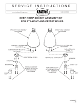
Legend
1
W
Welding
Power
Source
R
Remote
Control
Unit
S
Dual
Schedule
Switch
CF
Control/Feeder
Figure
4-1.
Gas
Metal-Arc
Welding
Connections
Condition
A
Voltage
Control
Condition
A
Pilot
Lamp
Condition
B
Voltage
Control
Ion
A
Wire
Speed
Control
Condition
B
Wire
Speed
Control
Figure
3-1.
Connectors
And
Controls
Condition
Selector
Condition
Selector
Receptacle
&
Plug
Receptacle
&
Plug
CF-RC4
CF-RC3
S
-
PIG1
:eeder/
CF
PLG4/
~Switch
(Mounted
Condition
Selector
_______________
______
On
Gun)
Condition
Selector
Receptacle
&
Plug
R
-
RC1
CF
-
PLG7
Page
2

4-1.
GAS
METAL-ARC
(GMAW)
WELDING
(Figure
4-1)
1.
Make
necessary
electrical
and
mechanical
connections
to
the
welding
power
source,
control/feeder,
and
gun
as
outlined
in
the
welding
power
source
manual,
control/feeder
manual,
and
gun
manual,
respectively.
2.
Make
Remote
VOLTAGE
CONTROL
connections
as
outlined
in
Section
2-1.
3.
Make
Remote
WIRE
SPEED
connections
as
outlined
in
Section
2-2.
4.
Make
Condition
Selector
connections
as
outlined
in
Section
2-3.
5.
Place
the
welding
power
source
LOAD
VOLTAGE
RANGE
switch
in
the
desired
position.
Due
to
the
circuitry
limitations
of
the
Remote
Control,
the
welding
power
source
may
not
be
used
in
the
MEDIUM
range
while
using
the
Remote
Control.
It
will
be
necessary,
therefore,
to
place
the
welding
power
source
LOAD
VOLTAGE
RANGE
switch
in
either
LOW.
HIGH,
or
WIDE
RANGE
when
using
the
Remote
Control.
NOTE
If
the
gun-mounted
Condition
Selector
switch
(option
al
equipment)
is
employed,
both
contactor
and
weld
ing
condition
control
are
provided.
This
switch
has
essentially
three
positions.
1.
In
the
first
switch
position,
to
which
the
switch
automatically
returns
if
no
switch
lever
pressure
is
applied,
the
welding
power
source
contactor
is
not
energized.
2.
In
the
second
switch
position,
which
is
obtained
by
depressing
the
switch
lever
about
half
way
down,
the
welding
power
source
contactor
is
energized
and
the
Remote
Control
is
placed
in
the
CONDI
TION
A
position.
3.
In
the
third
switch
position,
which
is
obtained
by
depressing
the
switch
lever
all
the
way
down,
the
welding
power
source
contactor
is
retained
in
an
energized
state
and
the
Remote
Control
is
placed
in
the
CONDITION
B
position.
Switching
the
Remote
Control
from
CONDITION
A
to
CONDITION
B
(or
from
CONDITION
B
to
CONDITION
A)
can
be
accomplished
by
varying
the
amount
of
pressure
applied
to
the
switch
lever.
4-2.
SHUTTING
DOWN
1.
Break
the
arc.
2.
Allow
the
welding
power
source
to
idle
for
3
minutes
with
no
load
applied.
3.
Place
the
welding
power
source
Power
switch
in
the
OFF
position.
Since
the
Remote
Control
derives
its
operating
power
from
the
welding
power
source,
the
Remote
Control
will
also
be
de-energized
when
the
welding
power
source
is
de-energized.
4.
Place
the
control/feeder
Power
Switch
in
the
OFF
position
if
the
control/feeder
is
provided
with
operating
power
external
to
the
welding
power
source.
5.
Turn
off
the
shielding
gas,
if
used,
at
the
shielding
gas
source.
CAUTION
I
U
If
welding
is
performed
in
a
confined
area,
failure
to
turn
off
the
shielding
gas
supply
could
result
in
a
build
up
of
gas
fumes,
thereby
endangering
personnel
reentering
the
welding
area.
I I
6.
Rotate
the
CONDITION
A
VOLTAGE
CONTROL
and
WIRE
SPEED
control
to
the
desired
setting.
7.
Rotate
the
CONDITION
B
VOLTAGE
CONTROL
and
WIRE
SPEED
control
to
the
desired
setting.
I
Prior
to
welding,
it is
imperative
that
proper
protective
clothing
(welding
coat
and
gloves)
and
eye
protection
(glasses
and/or
welding
helmet)
be
put
on.
Failure
to
comply
may
result
in
serious
and/or
permanent
bodily
damage.
U
I
8.
Turn
on
the
shielding
gas
supply,
if
used.
9.
Energize
the
welding
power
source
and
control/feeder.
Commence
welding.
10.
Welding
Condition
A
or
B
may
be
achieved
by
placing
the
Condition
Selector
in
the
position
corresponding
to
Condition
A
or
Condition
B,
respectively.
NOTE
L
CONDITION
A
and/or
B
VOLTAGE
CONTROL
and/or
WIRE
SPEED
control
may
be
adjusted
while
welding
to
achieve
optimum
welding
conditions.
OM-853
Page
3

~0
0)
Co
cv
AMPHENOL
PLUG
TO
WIRE
FEEDER
REMOTE
CONTROL
RECEPTACLE
GR-GROUND
TO
WELDING
MACHINE
PLG2
REMOTE
CONTROL
RECEPTACLE
C-COPPER
B-BRASS
Circuit
Diagram
No.
CA-DOD
461-lA
27
C
II
Ii
SHI
ELD
~1
1
II
II
~
>E
I
1
A
Figure
4-2.
Circuit
Diagram

March
1977
FORM:
OM-853
MODEL
RCMP-11
STOCK
NO.
000461
MODEL/STOCK
NO.
SERIAL/STYLE
NO.
DATE
PURCHASED
PARTS
LIST
MILLER
ELECTRIC
MFG.
CO.
APPLETON?
WISCONSIN,
USA
54911
NWSA
CODE
NO.
4579

Item
Dia.
Factory
No.
Mkgs.
Part
No.
Figure
A
Complete
Assembly
Description
Quantity
*Recommended
Spare
Parts.
BE
SURE TO
PROVIDE
STOCK,
MODEL,
AND
SERIAL
NUMBERS
WHEN
ORDERING
REPLACEMENT
PARTS.
OM-853
Page
1
1
2
2
3
4
5
6
7
8
9
10
11
12
13
14
15
16
17
18
19
20
21
22
23
24
PLG2
605797
600
733
010
610
RC1
039855
601
375
Cl
031
608
R7,8
030
653
023
235
019
663
R2,5
030131
034
338
104
045
039
664
CR1
034676
020
528
027
631
PL1,2
*027
638
027 628
019 609
019
627
039
828
057 057
PLG1
039827
CAP,
twistlock
3P3W
20
amp
115
volts
CORD
SET,
115
volts
l6ga
3/c
20
ft
CONNECTOR,
clamp
-
cable
1/2
inch
RECEPTACLE,
twistlock
2P2W
RING,
mounting
-
capacitor
1-3/8x
1-7/16
CAPACITOR,
electrolytic
250
uf
25
volts
ac
RHEOSTAT,WW
l50watt
15
ohm
CASE
SECTION,
base/sides
MOUNT,
neoprene
POTENTIOMETER,
carbon
I
turn
2
watt
50K
ohm
PANEL,
control
BRACKET,
mounting
-
socket
relay
SOCKET,
tube
11
pin
RELAY,
enclosed
24
volts
dc
3PDT
NAMEPLATE
(order
by
stock,
model,
and
serial
numbers)
HANDLE,
control
box
HOUSING,
light
-
indicator
slide
base
125
volts
BULB,
slide
base
48
volts
LENS,
light
-
indicator
red
clear
KNOB,
pointer
KNOB,
pointer
2
4
2
2
2
2
2
2
2
STRAIN
RELIEF,
receptacle/plug
CABLE,
electrical
No.
20
5/c
15
ft
PLUG,
6
pin
MS-3106A-14S-6P
19
18
17
20
21
20
19
18
17
16
Figure
A
-
Complete
Assembly
TD-009
497


I
/