Page is loading ...

1
©2019 Stillwater Designs
19418149-20190730
19418149
Designed for 2019 and newer
Chevrolet® Colorado and
GMC® Canyon Crew Cab
without HD radio
Not Compatible with Bose® system
Amplifier Assembly
Subwoofer Harness
Subwoofer Power Harness
Amplifier Power Harness
M6 Bolt X 2
7mm Screw
Threaded Clip
Fuse X 2
Wire Tie X 6
Foam Pad X 3
Amplifier Harness
Subwoofer Assembly

2
Fig. 2
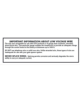
Insert terminals first.
Any wire can be in
any position.
Then
close
retainer
Fig. 3
Fig. 1
1. Disconnect negative battery cable.
2. Make sure supplied fuses are not installed in fuse holders. Open the battery distribution cover
and connect the subwoofer power wire and the amplifier power wire to the stud pictured in
figure 1 depending on which distribution block you have. Torque to 4.7Nm (42in-lb)
3. Route the power harnesses toward the firewall and secure with supplied wire ties.
4. Make a small incision in the grommet on the driver
side of the firewall and pass the power harnesses
into the cabin. Some models may have a small
nipple that can be cut off rather than making an
incision. Fig. 2
5. Install the white three pin power connector on the
amplifier power harness. Close the retainer. Fig. 3
Note: The terminals are keyed so that they only
install one way. If the terminal doesn’t want to
slide completely into the connector, it may
need to be rotated 180 degrees. It does not
matter which red wire goes in what position of
the connector.
Tip: Using a piece of stiff wire can help
in feeding the wires through the
grommet. Poke the stiff wire through
from inside the cabin and then tape the
power harnesses to the wire. Try to tape
the power wire so that the metal
terminals are not all trying to pass
through the grommet at the same time.
Slowly pull the stiff piece of wire to feed

3
Insert
terminal
first
Then
depress
blue
retainer
Fig. 4
6. Install the black two pin power connector on the
subwoofer power harness by first inserting the
terminal fully into the connector and then
depressing the blue retainer. Fig. 4
Note: Make sure the blue retainer in the center
of the connector is not depressed – it should
be flush with the front of the connector. If the
retainer is depressed, the terminal will not fully
seat in the connector body. Make sure the
terminal is installed into position 1 on the
connector body. There should be a block-out plug installed in position 2 in order to
prevent the terminal from being installed into the wrong position on the connector.
Radio Removal
7. Pull loose the radio bezel. Fig. 5
8. Remove the four screws securing the radio display/HVAC control panel. Fig. 6
9. Pull loose radio display/HVAC control panel and disconnect wiring. Note: Be careful not to
allow metal retainers to scratch dash!
Multi-Channel Amplifier Installation
10. Pull loose the dash end trim panel on the passenger side of dash. Fig. 7
11. Pull loose the passenger side front kick/threshold trim panel. Fig. 8
Fig. 6
Fig. 8
Fig. 5
Fig. 7

4
Fig. 12
Fig. 9
Fig. 11
Fig. 10
12. Remove the five screws and one plastic retainer securing the passenger side lower cover panel
below the glove compartment. To remove the plastic retainer, pry the center portion out first.
Fig. 9
Note: Some models may have a smaller
panel with only three screws.
13. Remove the glove compartment hinge pins by sliding them out. Fig. 10
14. Remove the glove compartment tension cable by sliding the hook toward the front of the glove
compartment. Remove the glove compartment from dash. Fig. 11
15. Install the supplied M6 clip nut onto the plastic tab
on the side of the blower housing. Fig. 12
Note: Some models may have a metal threaded
insert installed into the plastic tab by the
factory. If a metal threaded insert is present,
remove it and replace with the supplied M6 clip
nut.

5
Fig. 13
Fig. 14
Fig. 16
Fig. 15
16. Temporarily disconnect the HVAC blower fan wiring to allow the amplifier to be installed.
17. Secure the top of the multi-channel amplifier bracket with the supplied M6 bolt – leave loose.
Fig. 13
18. Install the supplied M6 bolt to secure the bottom of the multi-channel amplifier bracket to the clip
nut – leave loose. Fig. 14
19. Install the supplied screw in the location indicated in Fig. 15 and then tighten both M6 bolts.
Amplifier Harness Routing
20. Route the multi-channel amplifier harness from the
radio opening to the amplifier in a way that will not
interfere with the glove compartment function or
reinstallation of the radio display/HVAC control
panel.
21. Disconnect the 28-pin tan connector from the radio
module and connect it to the amplifier harness.
Fig. 16

6
Fig. 19
22. Connect the tan connector of the amplifier harness back to the radio module.
23. Disconnect the 28-pin green connector from the radio module. Carefully cut away
approximately 3 inches of black cloth wrapping the harness. Find the green with black stripe
wire and cut. Strip back about ¼ inch of wire on each cut end. Fig. 17
24. Using the supplied butt connectors, connect the harness wire labeled “connector” to the cut
wire attached to the radio connector. Connect the harness wire labeled “harness” to the other
cut wire. Fig. 18 See Splicing Technique Section.
25. Connect the two white multi-channel amplifier
connectors to the amplifier.
26. Ground the multi-channel amplifier harness to the
bolt securing the right side of the dash.
Fig. 19 Tighten to 19Nm (14ft-lb)
27. Connect the multi-channel amplifier harness three-
pin power connector to the three-pin power
harness connector.
Subwoofer Harness routing
28. Remove the driver side front and rear threshold panel along the bottom of the door opening.
29. Remove the filler panel on each side of the rear seat frame trim panel. Fig. 20
30. Remove the eleven bolts and rubber bumpers securing the rear seat frame trim panel and
remove the trim panel from vehicle. Fig. 21
Fig. 17
Fig. 18
Fig. 20
Fig. 21

7
Fig. 22
31. Connect the subwoofer harness two-pin power connector to the power harness two-pin
connector.
32. Route the subwoofer input connector (two-pin white) under the dash toward the passenger side
and connect it to the multi-channel amplifier connector.
33. Ground the subwoofer harness to the bolt securing
the left side of the dash. Fig. 22 Tighten to 19Nm
(14ft-lb)
34. Route the subwoofer harness along the driver side door openings. Pull harness under carpet
and through hole near rear seat frame on the driver side. Fig. 23
35. Make two ½ inch long cuts in carpet directly below the metal brace pictured in Fig. 24. Only cut
through the carpet layer, and not the insulation. The cuts should be approximately ½ inch apart.
36. Slide one of the supplied wire ties under the loop of carpet created in the previous step and
secure the harness to the carpet loop. Fig.25
37. Connect the subwoofer harness to the subwoofer. After connection, secure connector to
retention bracket on the bottom of the subwoofer enclosure.
38. Push down firmly on the subwoofer to slide it under the rear seat frame. Make sure the
subwoofer bracket is fully installed over the nut insert in the rear seat frame. Install the supplied
foam pieces along the front of the subwoofer enclosure where indicated in Fig. 26
Make two
cuts in carpet
approx. ½
inch long and
½ inch apart
directly
below metal
brace! Cut
carpet only,
not
insulation!
5 inches
from back
of bar
Fig. 24
Fig. 25
Foam pads
Fig. 26
Fig. 23

8
Fig. 27
39. Reinstall the rear seat frame trim panel over the
subwoofer enclosure and reinstall the bolts and
bumpers. It may be necessary to make slight
adjustments to the subwoofer enclosure or rear
seat trim panel position to perfectly center the
enclosure. Reinstallation of the two filler panels on
each side of the seat frame trim panel is possible,
but not necessary. Fig. 24
40. Reinstall all previously removed parts in reverse
order.
41. Install supplied fuses into fuse holders.
42. Reconnect negative battery cable. Tighten to 7.5Nm (66in-lb)

9
Troubleshooting the Kicker Integrated Systems
If you experience a problem once the subwoofer or amplifier are installed use this guide to locate the trouble.
The radio is working, but the Subwoofer is not working:
• Check the battery voltage to make sure it is not discharged below 11 volts.
• Check the negative battery cable to see if it has been securely tightened back on the battery.
• Check the inline fuse located near the battery to make sure it is plugged in completely, and not blown.
• Check the inline +12 volt power connector near the firewall to make sure it is plugged in securely.
• Check the inline connectors near the subwoofer enclosure to make sure they are plugged securely.
• Check the ground wire connection to make sure it is tightly secured to the proper ground in the vehicle.
• Check the audio input signal connection to make sure it is secure and connected to the proper wiring.
• Test with different music in case there is no low frequency audio in the initial sound check.
There is a problem with the multi-channel stereo amplifier:
• Check the battery voltage to make sure it is not discharged below 11 volts.
• Check the negative battery cable to see if it has been securely tightened back on the battery.
• Check the inline fuse located near the battery to see if it is plugged in completely and not blown.
• Check the multi-pin connectors at the back of the radio and at the amplifier chassis to make sure they are
plugged all the way in.
• Check the ground wire connection to make sure it is tightly secured to the proper ground in the vehicle.
Symptom
Possible Cause
Solution
No Subwoofer Output
Fuse not installed in inline fuse
holder on subwoofer and/or
amplifier power harness
Install fuse into fuse holder.
Refer to instructions for correct
placement
Low battery voltage
Recharge the battery
Negative battery cable not
connected
Reconnect negative battery
cable
Power wire connector not
connected to body harness
Connect power wire to body
harness. Check for loose
connection
Ground wire not grounded properly
Check ground wire with voltmeter
to insure it is a good ground
Balance and/or fader controls not
set to neutral position
Set balance and fader control to
center settings. (only affects
stand-alone subwoofer kit)
No low frequency information in
music
Test with several different songs
Subwoofer harness not
properly/completely connected to
subwoofer
Securely fasten both of the
connectors on the subwoofer
harness to the subwoofer.
Check for loose connectors.
Radio Not Coming On
Blown radio fuse
Refer to owner’s manual for radio
fuse location and value
Low battery voltage
Recharge the battery
Radio Comes On, But No
Sound From Any Speakers
Fuse not installed in inline fuse
holder on amplifier harness
Install fuse into fuse holder.
Refer to instructions for correct
placement
Ground wire not grounded properly
Check ground wire with voltmeter
to insure it is a good ground
Low battery voltage
Recharge the battery

10
Splicing Technique
Splicing Copper Wire Using Splice Sleeves
Special Tools:
•
EL-38125-10 Splice Sleeve Crimping Tool
•
J-38125-5A Ultra Torch Special Tool
•
J-38125-8 Splice Sleeve Crimping Tool
NOTE: The DuraSeal splice sleeves have the following 2 critical features:
•
A special heat shrink sleeve environmentally seals the splice. The heat shrink sleeve contains a
sealing adhesive inside.
•
A cross hatched (knurled) core crimp provides the necessary low resistance contact integrity
for these sensitive, low energy circuits.
Use DuraSeal splice sleeves where there are special requirements such as moisture sealing. Follow the
instructions below in order to splice copper wire using DuraSeal splice sleeves.
Splice Sleeve Color
Crimp Tool Nest Color
Wire Gauge mm² / (AWG)
3 Crimp Nests
4 Crimp Nests
Salmon (Yellow-Pink)
19168446
Red (1) or Red/Green
Red (2)
0.5–0.8/(18–20)
Blue
19168447
Blue (2)
Blue (3)
1.0–2.0/(14–16)
Yellow
19168448
Yellow (3)
Yellow (4)
3.0–5.0/(10–12)
NOTE: You must perform the following procedures in the listed order. Repeat the procedure if any wire
strands are damaged. You must obtain a clean strip with all of the wire strands intact.

11
Open the harness by removing any tape:
•
Use a sewing seam ripper, available from sewing supply stores, in order to cut open the
harness in order to avoid wire insulation damage.
•
Use the DuraSeal splice sleeves on all types of insulation except Tefzel and coaxial.
Cut as little wire off the harness as possible. You may need the extra length of wire in order to change the
location of a splice.
Adjust splice locations so that each splice is at least 40 mm (1.5 in) away from the other splices, harness
branches, or connectors.
Strip the insulation:
•
When adding a length of wire to the existing harness, use the same size wire as the original wire.
•
Perform one of the following items in order to find the correct wire size:
NOTE: Find the wire on the schematic and convert to regional wiring gauge size.
If you are unsure of the wire size, begin with the largest opening in the wire stripper and work down
until achieving a clean strip of the insulation.
•
Strip approximately 5.0 mm (0.20 in) of insulation from each wire to be spliced.
•
Do not nick or cut any of the strands. Inspect the stripped wire for nicks or cut strands.
•
If the wire is damaged, repeat this procedure after removing the damaged section.
For high temperature wiring, slide a section of high
temperature SCT1 shrink tubing down the length of wire to
be spliced. Ensure that the shrink tubing will not interfere
with the splice procedure.
Select the proper DuraSeal splice sleeve according to the wire
size. Refer to the above table at the beginning of the repair
procedure for the color coding of the DuraSeal splice
sleeves and the crimp tool nests.
The EL-38125-10 splice sleeve crimping tool has four crimp
nests. The largest crimp nest (4) is used for crimping 10
and 12 gauge wires. The second largest crimp nest (3) is
used for crimping 14 and 16 gauge wires. The third largest
crimp nest (2) is used for crimping 18 and 20 gauge wires.
The smallest crimp nest (1) is used for crimping 22 to 26
gauge wires. The crimp nests are referenced in the table
(farther above) under the crimp tool nest color.

12
The J-38125-8 splice sleeve crimping tool has three crimp nests.
The largest crimp nest (3) is used for crimping 10 and 12
gauge wires. The second largest crimp nest (2) is used for
crimping 14 and 16 gauge wires. The smallest crimp nest (1)
is used for crimping 18 to 20 gauge wires. The crimp nests
are referenced in the table (farther above) under the crimp
tool nest color.
Use the splice sleeve crimp tool in order to position the DuraSeal splice sleeve in the proper color nest of the
splice
sleeve crimp tool. For the four crimp nest tool, use the three largest crimp nests to crimp the splice
sleeves. For the
three crimp nest tool, use all three crimp nests to crimp the splice sleeves. Use the four and
three crimp tool
diagrams (above) and the table (farther above) to match the splice sleeve with the correct
crimp nest. The crimp tool
diagram callout numbers match the numbers in the table (under crimp tool nest
color).
Place the DuraSeal splice sleeve in the nest. Ensure that the crimp falls midway between the end of the barrel and the
stop. The sleeve has a stop (3) in the middle of the barrel (2) in order to prevent the wire (1) from
going further. Close
the hand crimper handles slightly in order to firmly hold the DuraSeal splice sleeve in the
proper nest.
Insert the wire into the splice sleeve barrel until the wire hits the barrel
stop.
Tightly close the handles of the crimp tool until the crimper handles
open when released.
The crimper handles will not open until you apply the proper amount of
pressure to the DuraSeal splice sleeve. Repeat steps 4 and 6 for
the opposite end of the splice.
Using the heat torch, apply heat to the crimped area of the barrel.
Start in the middle and gradually move the heat barrel to the open ends of the tubing:
•
The tubing will shrink completely as the heat is moved along the insulation.
•
A small amount of sealant will come out of the end of the tubing when sufficient shrinkage is
achieved.

/