Page is loading ...

®
ELECTRONIC 7-DAY
WATER HEATER TIME SWITCHES
MODELS EH10, 120V AND EH40, 240V
WITH BATTERY CARRYOVER
OWNER/INSTALLER INSTRUCTION MANUAL
RETAIN FOR FUTURE REFERENCE.
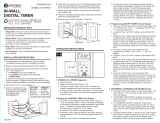
MANUAL (MAN) - AUTOMATIC (AUTO)
(See Fig. 1)
• MANUAL: Bypasses your program completely; timer
will not resume program until you return switch to
AUTO mode position.
• AUTOMATIC: For automatically switching at ON/OFF
times; accurate to-the-minute.
PROGRAM (PROG) - RUN - TIME SET
• PROGRAM: Use this position when programming.
• RUN: Use this position for normal operation. Be sure to
return to RUN after setting time and program.
• TIME SET: Use this position to set day and time of day.
ON/OFF - EVENT (the large push button) - Serves a
dual purpose
• EVENT: Used for programming (active only when switch
is set at PROG).
• ON/OFF: Override (active only when switch is set at
RUN); turns load ON if already off or OFF if already on.
Timer automatically resumes program cycle only when
slide switch is in AUTO. Note that this button is also
accessible without opening the enclosure.
SPECIFICATIONS:
Clock Voltage - Model EH40 - 240V. A.C., 50/60 Hz
EH10 - 120V. A.C., 50/60 Hz
Power Consumption - EH10 - 1.0 W. Max., EH40 - 3.0
W. Max.
Contact Configuration - EH10 (SPST) Single pole-single
throw model- EH40(DPST) Double pole-single throw model
MAN
AUTO
PROG
RUN
TIME
SET
ON
OFF
EVENT
DAY
HOUR
MIN
LOAD
RESET
BATTERY
®
Fig.1
Set Points (Events) - 12 total (6 ON/6 OFF) - Can be
assigned in any combination to weekdays, weekend days,
daily or weekly operation providing up to a maximum of 84
weekly operations (42 ON/42 OFF).
Battery Powered Clock Operation - 3 years minimum,
AA industrial grade alkaline supplied with time switch.
Minimum ON/OFF Time - 1 Minute
Maximum ON/OFF Time - 6 days 23 hours 59 minutes
Shipping Weight - 2.37 Lbs. (1.05 Kg)
Case - Drawn steel, 7-3/4" (19.7 cm) high, 5" (12.7 cm)
wide, 3" (7.6 cm) deep; gray finish with lockable spring
hasp, clear see-through viewing window and external
override.
Knockouts - Combination of 1/2 - 3/4" (one on back and
each side, two on bottom)
Wire Size - AWG #10.
GENERAL SAFETY INFORMATION:
1. Mount the time switch in the desired location using the
three mounting holes which are provided. Mount the
time switch at eye level, if possible, providing sufficient
room to the left of the enclosure for the cover to swing
open fully. (See Fig. #2). The time switch mechanism
does not need to be removed from the enclosure to
mount the time switch since the top mounting hole is
a slotted type mounting hole. Secure a screw or other
fastener at eye level. The head of the screw of fastener
should be slightly larger than the narrow portion of the
slotted hole to ensure that the time switch is securely
held in place. The remaining two mounting holes
provide a means to secure the time switch.
2. If you do remove the mechanism, refer to Figure #3 and
remove the mechanism from the case by depressing
the catch at the top of the case and pulling out.
Fig. 3
Fig.2
Mounting Holes
Knockouts
Ground
Terminal
Snap Out Catch
Tilt Top Forward
Lift Up
To
Remove
3. Replace the mechanism in the case if it has been
removed, making sure to engage ribs at sides of
mechanism between ears at sides of case before
snapping in place.
4. Lift the left side of the insulator off of the retaining
post and pivot it up and away to expose the terminal
screws.
5. Strip the supply and load wires by removing 1/2 inch
of insulation. DO NOT USE ALUMINUM WIRE. Insert
the wire ends under the proper terminal plates and
tighten the screws firmly. Use any size wire AWG #10.
Connect ground wire to grounding terminal at bottom
of case.
6. Replace the plastic insulator.
7. Follow instructions for battery installation. Be sure
that the battery is functioning properly. This can be
checked by seeing that the display is visible. If the
display has scrambled information, check to be sure
that the polarity orientation of the battery is as shown
on the cover label, then press the RESET switch and
hold for at least two seconds. Note that the battery
can easily be replaced without removing the time
switch mechanism or field wiring. Simply press in and
downward (in the direction of the arrow) on the battery
cover which is identified with the word “Battery”.
It is recommended that the battery be replaced with
a “AA” industrial grade alkaline cell at two to three
Switch Rating (Per Pole) -
• 30 amp inductive/resistive - 120-240V. A.C., 60 Hz
• 1 H.P. 120V. A.C., 60 Hz.
• 1-1/2 H.P. 240V. A.C., 60 Hz.
• 5 amp tungsten, 120-240V. A.C., 60 Hz.
Risk of Fire or Electric Shock
• Disconnect power at the circuit breaker(s) or disconnect switch(es) before installing
or servicing.
• More than one circuit breaker or disconnect switch may be required to de-energize
the equipment before servicing.
• Installation and/or wiring must be in accordance with National and Local Electrical
Code requirements.
• Use #10 AWG wires - COPPER conductors ONLY.
NOTICE
• Do not touch circuit board components; contact can create a static discharge, which
can damage the microprocessor.
WARNING

year intervals as part of the normal time switch maintenance
observing battery polarity markings when installing. No
other maintenance is required.
8. Place the slide switches in the AUTO and RUN position.
9. Reapply power to the time switch.
10. Press the recessed reset switch for at least two seconds.
The display will show 12:00 A.M. and MO. Note that the
days of the week are identified with the first two letters
of the day (MO for Monday). The timer is now ready for
programming. Refer to the examples which follow and
enter the scheduled events (set points) required. Assign
each of the 12 set points (EVENTS) entered to whichever
day or groups of days of the week you wish an ON or OFF
operation to occur.
Set Point = Event = ON = OFF
PROGRAMMING STEPS:
SET CURRENT DAY AND TIME
Slide switch to TIME SET. Push DAY until current day
shows, then push HOUR until current hour AM or PM
shows. Now push MINUTE until current minute shows.
Clock is now set. Follow same procedure after replacing
battery or changing time (such as for daylight saving time).
SET YOUR PROGRAM
Slide switch to PROG. Display will look like this: (-:- -)
• Press DAY until desired program period shows (see
choices in “PROGRAM PERIOD OPTIONS” section above).
• Press HOUR until desired “ON 1” hour shows
(that is, the first time each day of the program
period that you want the load to turn ON).
• Press MINUTE until desired minute shows.
• Press EVENT to program time for ON 1
(and to advance to programming for OFF 1).
• Press DAY again until all seven days of the
week show (or until another desired program
period option shows; see “PROGRAM PERIOD
OPTIONS”).
• Press HOUR again until desired “OFF 1” hour shows
(that is, the first time each day of the program
period that you want the devices to turn OFF).
• Press MINUTE until desired minute shows.
• Press EVENT to set time for OFF 1. You may now begin
setting ON 2, a second ON time, for the same program period,
OR press DAY to change to a different program period.
• Repeat above procedure until all desired ON/OFF
programs are set.
PLEASE NOTE: Before you program your timer, or when you
remove the battery, or when you use the RESET, pressing
EVENT will display the bar symbol -:-- ON 1. Repeated
pressing of EVENT will display all the way through the final bar
symbol -:-- OFF 6. Once you program your timer, however,
each actual time setting you make will replace the bar symbol.
While programming, each time you press EVENT you will
advance to the next EVENT.
PROGRAM PERIOD OPTIONS:
Your timer gives you up to 6 different ON and 6 different OFF
settings per program period. You can use all 6 settings per
period, or as few as you like. A program period covers one of
these:
• ALL 7 DAYS OF THE WEEK combined into one - display
shows: MO TU WE TH FR SA SU.
• MONDAY THRU FRIDAY combined into one -
display shows: MO TU WE TH FR.
• SATURDAY AND SUNDAY combined into one -
display shows: SA SU.
• EACH INDIVIDUAL DAY OF THE WEEK -
display shows only that day.
• BLANKDAY EXPLANATION - “BLANKDAY”
follows Sunday after last push of DAY button (when
the lower slide switch is set at PROGRAM). The
purpose of the BLANKDAY is to disable a program
setting on a day.
Program periods with days “combined into one” help
you make settings for those multiple days quickly and
conveniently while using only one ON/OFF pair. When you
set such a program period, all settings will be identical for
every day of that period.
PERSONAL PROGRAM EXAMPLES
EVENTS
DAY CHECKS ON TIMES OFF TIMES DISPLAYED DAYS & TIMES DISPLAYED
EXAMPLE 1
MO TU WE TH FR SA SU 5:00 PM 10:00 PM ON 1 MO TU WE TH FR SA SU 5:00 PM
OFF 1
EXAMPLE 2
MO TU WE TH FR 6:00 PM 10:00 PM ON 1 MO TU WE TH FR 6:00 PM
OFF 1 MO TU WE TH FR 10:00 PM
SA SU 4:00 PM 8:00 PM ON 2 SA SU 4:00 PM
OFF 2 SA SU 8:00 PM
EXAMPLE 3
MO TU WE TH FR 6:00 AM 9:30 AM ON 1 MO TU WE TH FR 6:00 AM
OFF 1 MO TU WE TH FR 9:30 AM
MO TU WE TH FR 5:30 PM 11:15 PM ON 2 MO TU WE TH FR 5:30 PM
OFF 2 MO TU WE TH FR 11:15 PM
SA SU 3:00 PM 10:00 PM ON 3 SA SU 3:00 PM
OFF 3 SA SU 10:00 PM
EXAMPLE 4
MO TU WE TH 8:00 PM 11:30 PM ON 1 MO TU WE TH 8:00 PM
OFF 1 MO TU WE TH 11:30 PM
FR SA 5:00 PM 2:20 PM ON 2 SU 7:00 PM
(DAY AFTER) OFF 2 SU 10:30 PM
SU 7:00 PM 10:30 PM ON 3 FR 5:00 PM
OFF 3 MO 11:30 PM
ON 4 SA 5:00 PM
OFF 4 TU 11:30 PM
ON 5 “BLANKDAY” -:- -
OFF 5 WE 11:30 PM
ON 6 “BLANKDAY” -:- -
OFF 6 TH 11:30 PM
NOTE: “-:- -” follows Sunday after last push of DAY button
(when the slide switch is set at PROG). The purpose of the
-:- - is to cancel a program setting on that day.
REVIEW YOUR PROGRAM
Slide switch to PROG. Press EVENT button to advance
display to each ON or OFF setting. Check days and times
displayed. To make a change, follow instructions under
“SET YOUR PROGRAM”. To delete a displayed set point,
press DAY button until “-:- -” is displayed.
GENERAL FEATURES AND HINTS FOR TROUBLE
FREE USE
• BUTTON: When you press a button, there is an advance
of one time unit; holding a button down advances
continuously until released.
• MAINTENANCE: With the exception of battery
replacement at 2-3 year intervals, your Intermatic timer
is maintenance-free.
• AFTER THE INSTALLATION IS COMPLETED, THE
LOCKABLE HASP SHOULD BE MOVED TO THE UP
POSITION TO ENGAGE THE COVER WHEN IT IS
CLOSED.
LIMITED ONE-YEAR WARRANTY
If within the warranty period specified, this product fails due to a defect in material or
workmanship, Intermatic Incorporated will repair or replace it, at its sole option, free of
charge. This warranty is extended to the original household purchaser only and is not
transferable. This warranty does not apply to: (a) damage to units caused by accident,
dropping or abuse in handling, acts of God or any negligent use; (b) units which have been
subject to unauthorized repair, opened, taken apart or otherwise modified; (c) units not used
in accordance with instructions; (d) damages exceeding the cost of the product; (e) sealed
lamps and/or lamp bulbs, LED’s and batteries; (f) the finish on any portion of the product,
such as surface and/or weathering, as this is considered normal wear and tear; (g) transit
damage, initial installation costs, removal costs, or reinstallation costs.
INTERMATIC INCORPORATED WILL NOT BE LIABLE FOR INCIDENTAL OR
CONSEQUENTIAL DAMAGES. SOME STATES DO NOT ALLOW THE EXCLUSION
OR LIMITATION OF INCIDENTAL OR CONSEQUENTIAL DAMAGES, SO THE ABOVE
LIMITATION OR EXCLUSION MAY NOT APPLY TO YOU. THIS WARRANTY IS IN LIEU
OF ALL OTHER EXPRESS OR IMPLIED WARRANTIES. ALL IMPLIED WARRANTIES,
INCLUDING THE WARRANTY OF MERCHANTABILITY AND THE WARRANTY OF FITNESS
FOR A PARTICULAR PURPOSE, ARE HEREBY MODIFIED TO EXIST ONLY AS CONTAINED
IN THIS LIMITED WARRANTY, AND SHALL BE OF THE SAME DURATION AS THE
WARRANTY PERIOD STATED ABOVE. SOME STATES DO NOT ALLOW LIMITATIONS ON
THE DURATION OF AN IMPLIED WARRANTY, SO THE ABOVE LIMITATION MAY NOT
APPLY TO YOU.
This warranty service is available by either (a) returning the product to the dealer from
whom the unit was purchased or (b) completing a warranty claim online at www.
intermatic.com. This warranty is made by: Intermatic Incorporated, Customer Service
7777 Winn Rd., Spring Grove, Illinois 60081-9698. For warranty service go to: http://
www.intermatic.com or call 815-675-7000.
INTERMATIC INCORPORATED
SPRING GROVE, ILLINOIS 60081-9698
- 2 -
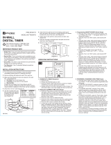
TIMER
POWER
LOAD
NEUTRAL
NEUTRAL
1
2 3 4
Fig. 4
Fig. 5
TIMER
POWER
1
2 3
4
5 6
LINE 1
LINE
LINE
LINE 2
LINE 1
LINE 2
LOAD
120 ≈
240≈
EH10
EH40

- 8 -
INTERMATIC INCORPORATED
SPRING GROVE, ILLINOIS 60081-9698
158--01586
/