Page is loading ...

All disclosures, notices and warranty conditions are being written on EKWB website. Please check terms of use. Revision 1.0. Released on 10
th
of August, 2012.
Installation and mounting manual for EK-VGA Supremacy water block
This product is intended for installation only by expert users. Please consult with a qualified technician for installation. Improper installation may result in damage to your equipment. EK Water Blocks assumes no liability
whatsoever, expressed or implied, for the use of these products, nor their installation. The following instructions are subject to change without notice. Please visit our web site at www.ekwb.com for updates. Before
installation of this product please read important notice, disclosure and warranty conditions printed on the back of the box.
Before you start using this product please follow these basic guidelines:
1. Please carefully read the manual before through before beginning with the installation process!
2. The EK High Flow and EK-PSC type fittings require only a small amount of force to screw them firmly in place since the liquid seal is ensured by the rubber o-ring gaskets.
3. This product is not compatible with EK-PSC compression fittings bigger than 10mm!
4. The use of quality, market proved corrosion inhibiting coolants is always strongly recommended for any liquid cooling system.
STEP 1: GENERAL INFORMATION
STEP 1 cont.: GENERAL INFORMATION
Please remove your card from the computer to assure safest mounting
process possible in order to prevent any possible damages to your PCB.
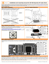
Picture bellow represents the correct orientation of jet plate.
STEP 2: PREPARING YOUR HARDWARE STEP 3: ATTACHING WATERBLOCK
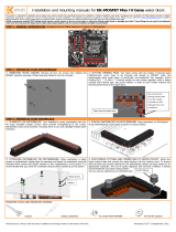
CLEANING THE GPU.
Wipe off the remains (by using non–
abrasive cloth or
qtip
) of the original thermal compound until the
components
and circuit board are completely clean. EKWB
recommends the use of denatured alcohol for removing TIM
leftovers.
APPLYING THERMAL COMPOUND. Apply thermal compound:
lightly coat GPU chip with for example Arctic Cooling MX-2 ™ or
MX-4 ™ thermal grease. EKWB recommends
to apply thermal
grease in cross form for best performance (see picture below).
“NAKED” GPU
e.g. Radeon HD 6970
GPU WITH HEATSPREADER
e.g. GeForce GTX 580
Please make sure to install the waterblock so the G1/4 threaded inlet/outlet ports are turned away
from the PCI-e connector slot! Only this way you will be able to connect block properly into loop.
STEP 4: CONNECTING WATERBLOCK
Carefully identify the direction of the flow in your circuit. For the EK-VGA Supremacy series water block to operate properly it is mandatory to use the dedicated INLET/OUTLET
openings as shown on picture below. To ensure that the tubes are securely attached to the barb/fittings, please use hose clamps or an appropriate substitute.
IMPORTANT DISCLOSURES
VERY IMPORTANT NOTICE: Once the installation is completed, it is a recommended practice to test the cooling circuit for leaks prior to powering up the computer. We recommend a 24 hour leak test prior to powering up
the computer. Do not test the water block using city water pressure. This will rupture the top of the housing and render the block unusable (and will void your warranty). While all efforts have been made to provide the most
comprehensive tutorial possible, EK Water Blocks assumes no liability expressed or implied for any consequential damage(s) occurring to your equipment as a result of using EK Water Blocks cooling products, either due to
errors or omissions on our part in the above instructions, or due to failure or defect in the EK Water Blocks cooling products.
CORRECT
INCORRECT
All chips, marked RED and BLUE, must be
passively cooled. This is an example shown
on GTX 6
80 reference design graphics
card. EK suggests users to check their
factory cooling solution and locate the ICs
which are being actively cooled besides
the GPU itself. We recommend applying
self-adhesive heat-sinks on the same IC.
It is important to cool VRM- and RAM IC
on modern high-performance graphics
cards!
!!!VERY IMPORTANT!!!
GPU WITH HEATSPREADER
(IHS): Use standoffs
(2.1mm)
»NAKED« GPU:
Replace standoffs with
enclosed 0.8mm PVC
washers.
Thumb nut is to be fastened
by hand. Please use enclosed
allen key only if necessary.
Once thumb nut can't be
turned any more the
maximum mounting force has
been reached.
If the mounting screw
eventually starts turning
maximum force has been
reached.
M3x12 DIN7984 screws
Mounting plate
Jet plate
Water block top
Water block copper base
Mounting screw
Polyamid washer
Coiled Spring
Thumb nut
M2.5x6 screw
RAM IC
VRM IC
/


