-. For Active Subwoofer & Satellite Speakers
6
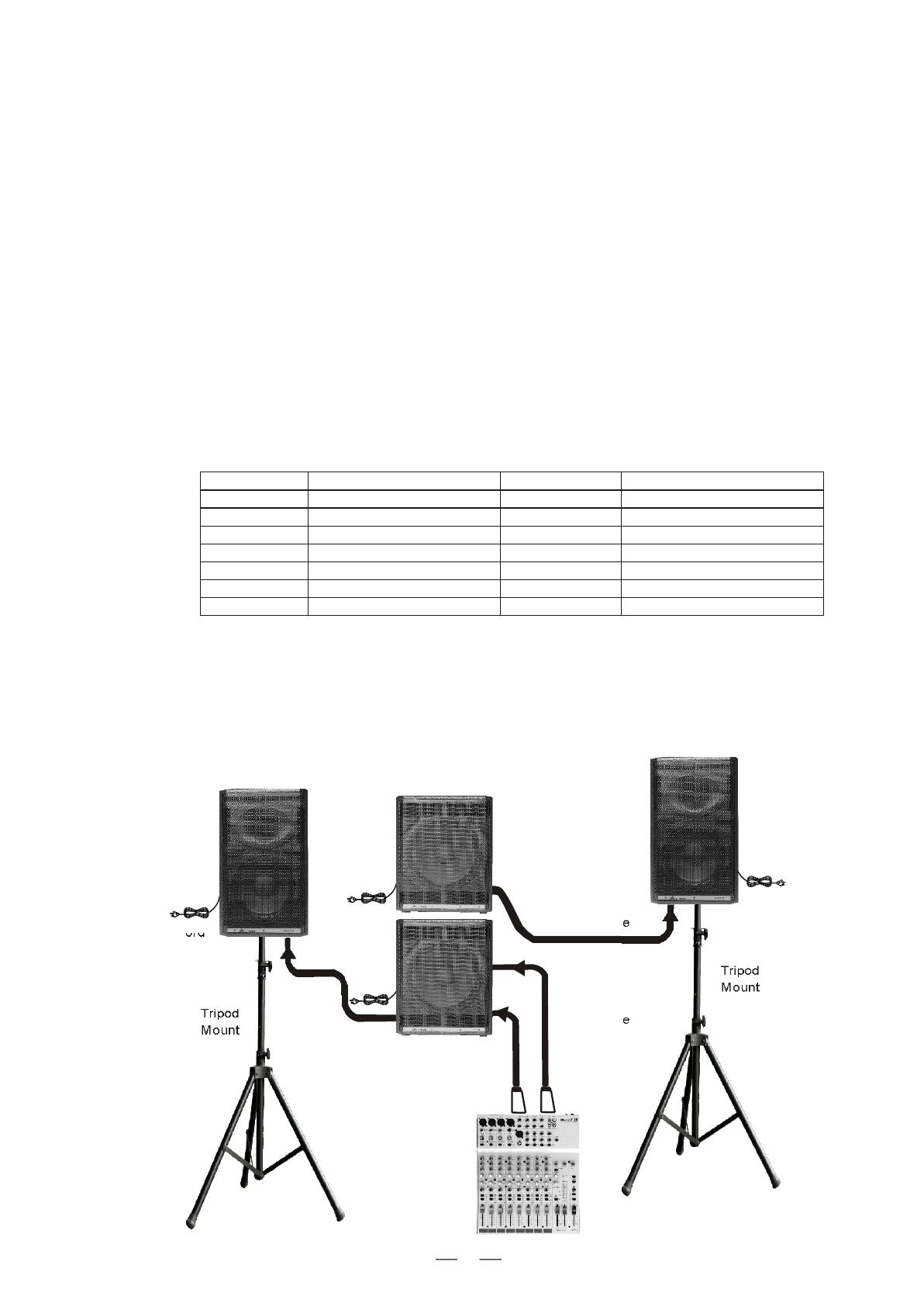
Tripod
Mount
Tripod
Mount
Left
Main Mix
Output
Right
Main Mix
Output
QUICK START
SR Active Subwoofer & Satellite Speakers
Signal Cable
Signal Cable
Power Cord
2). Connect the power cord to mains.
3). Turn on your mixer first, then the active speaker cabinets.
4). Turn up the volume control fo the active speaker cabinets.
8). After using, turn off your active speaker cabinets first, then the mixer.
1). Connect one side of signal cable to output left/right of your audio mixer (with stereo-Jack or XLR) and the other
side to the left/right input (stereo/mono XLR) of the active subwoofer; with the second signal cable connect the
left/right output of the subwoofer (stereo/mono- XLR) to the line input (COMBO) of the active satellite (with stereo -
Jack or XLR).
7). Use PFL function to get the proper input level for the mixer, and adjust the main mix level control to manipulate the
output level.
5). Select one of the sixteen presets in to SR400A, with encoder knob (example: number 15 - DISCO + SW).
6). The Subwoofer SR500SA work with 16 presets, select the best crossover frequency presets between 1 (80Hz
BOOST 0 ) in phase or 2 (80Hz BOOST 180 ) out of phase, to 9 (160Hz BOOST 0 ) in phase or 10 (160Hz BOOST
180 ) out of phase, this preset included a +6dB bass boost; the other presets between 11 (100Hz FLAT 0 ) in
phase or 12 (100Hz FLAT 180 ) out of phase to 15 (140Hz FLAT 0 ) in phase or 16 (140Hz FLAT 180 ) out of
phase, work with a Natural Bass response, if required from the musical program.
Select one of the sixteen presets in to SR500SA, with encoder knob (example: number 4 - 100Hz BOOST 180
out of phase, or the number 6 - 120Hz BOOST 180 ) out of phase, for coupling to the preset 15 - DISCO + SW
of the satellite. The selection of phase conditions between 0 in phase or 180 out of phase is always necessary
after the setting of SR500SA in the environment
PRESET
10
11
12
13
14
15
16
CONCERT H. + SW
LIVE + SW
FLAT + SW
JAZZ + SW
ROCK + SW
DISCO + SW
KARAOKE + SW
SR400A SATELLITE PRESET
1-2-3-4
3-4-5-6
11-12-13-14
11-12-13-14
3-4-5-6
3-4-5-6
1-2-3-4
SR500SA SUBWOOFER
80Hz/100Hz BOOST 0 /180
100Hz/120Hz BOOST 0 /180
100Hz/120Hz FLAT 0 /180
100Hz/120Hz FLAT 0 /180
100Hz/120Hz BOOST 0 /180
100Hz/120Hz BOOST 0 /180
80Hz/100Hz BOOST 0 /180


