

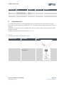
AS5601 Adapter Board
ams Eval Kit Manual, Confidential
Page 2
[v1-00] 2014-Jul-31
Document Feedback
Table of Contents
1 Introduction .......................................................................................................................... 3
2 Kit Content ........................................................................................................................... 3
3 Getting Started ..................................................................................................................... 3
3.1 Adapter Board Pin-Out ......................................................................................................... 3
4 Adapter Board Description ................................................................................................... 4
5 Mechanical Setup ................................................................................................................. 4
5.1 Electrical Setup .................................................................................................................... 5
5.1.1 I
2
C Mode .............................................................................................................................. 5
5.1.2 Incremental Mode ................................................................................................................ 6
6 AS5601 Configuration .......................................................................................................... 6
6.1 Configuring the grid offset .................................................................................................... 6
6.2 Configuring the grid push button threshold .......................................................................... 7
6.3 Permanently programming a configuration .......................................................................... 7
6.3.1 Low Power Mode ................................................................................................................. 7
6.3.2 Hysteresis ............................................................................................................................ 8
6.3.3 Slow Filter ............................................................................................................................ 8
6.3.4 Fast Filter ............................................................................................................................. 8
6.3.5 Watchdog ............................................................................................................................. 8
7 Board Schematics, Layout and BOM ................................................................................... 8
7.1 Schematics ........................................................................................................................... 8
7.2 Layout and Board Dimensions ............................................................................................. 9
7.3 Bill of Materials ..................................................................................................................... 9
8 Evaluation tools .................................................................................................................. 10
9 Ordering & Contact Information ......................................................................................... 11
10 Copyrights & Disclaimer ..................................................................................................... 12
11 Revision Information .......................................................................................................... 13

AS5601 Adapter Board
ams Eval Kit Manual, Confidential
Page 3
[v1-00] 2014-Jul-31
Document Feedback
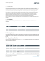
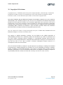
1 Introduction
The adapter board allows an easy and fast evaluation of the AS5601 rotary magnetic position
sensor in the lab or together with an existing system. This small factor board is fully assembled with
AS5601 position sensor and its necessary external components. All relevant signals are available
on a dual-row 2.54mm 4-pin header footprint and can be easily wired to an existing application.
The AS5601 is an easy-to-program magnetic rotary position sensor with incremental quadrature
(A/B) and 12-bit digital outputs. Additionally, the PUSH output indicates fast airgap changes
between the AS5601 and magnet which can be used to implement a contactless pushbutton
function in which the knob can be pressed to move the magnet toward the AS5601.
The I²C interface is used for configuration and user programming of non-volatile parameters in the
AS5601.
2 Kit Content
This kit contains following material listed in Table 1. Additional material can be found on our
webpage.
Table 1:
Kit Content
No.
Item
Description
Info
1
AS5601-SO_EK_AB
2
AS5000-MD6H-1
Reference Magnet
Find the datasheet online at
http://ams.com/eng/AS5000-MD6H-1
3 Getting Started
The AS5601 adapter board is ideal for rapid setup of a contactless encoder knob. Additionally to the
adapter board, a sensor magnet in a mechanical setup is required. A reference magnet comes with
the kit.
3.1 Adapter Board Pin-Out
The pin-out of the adapter board is shown in Table 2. For additional information on the AS5601 pins
refer to the product datasheet.
Table 2:
Adapter Board Pin-Out
Header
Pin
Symbol
Description
Info
J3
1
SCL
I2C Clock
Use R3 if pull-up is required
J3
2
SDA
I2C Data
Use R4 if pull-up is required
J3
3
GND
Ground
J3
4
VDD
Positive Power
Supply
J2
1
VRG
LDO Pin in 5V
Leave open in 5V mode. Pull to VDD using

AS5601 Adapter Board
ams Eval Kit Manual, Confidential
Page 4
[v1-00] 2014-Jul-31
Document Feedback
Header
Pin
Symbol
Description
Info
Mode
J1 in 3.3V Mode
J2
2
B
Output Pin
Quadrature incremental signal B
J2
3
A
Output Pin
Quadrature incremental signal A
J2
4
PUSH
Output Pin
Contactless pushbutton function output
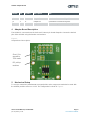
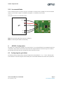
4 Adapter Board Description
The AS5601 is connected over the dual-row 2.54mm 4-pin header footprint. Connect the desired
pins of the AS5601 using the headers and resistors.
Figure 1:
Adapterboard Description
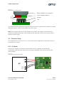
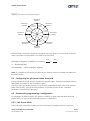
5 Mechanical Setup
To set up a contactless potentiometer a magnet holder and a magnet are needed to be used with
the AS5601 position sensor on a PCB. The configuration is shown in Figure 2.
I2C pull-up
resistors
Short J1 to
operate in
3.3V mode

AS5601 Adapter Board
ams Eval Kit Manual, Confidential
Page 5
[v1-00] 2014-Jul-31
Document Feedback
Figure 2:
Mechanical Configuration
The magnet should be aligned by reading the output of the AGC register of the AS5601. For optimal
alignment, the AGC value is in the middle of the AGC range.
Note: If the magnetic field seen by the AS5601 is below 8mT, the output is disconnected and
permanent angle programming is not possible. The AB output will not show any change until the
magnet is present again.
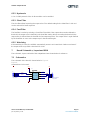
5.1 Electrical Setup
The Adapterboard can be used in 5V or in 3.3V mode in the configurations shown below. Short J1
to operate in 3.3V mode.
5.1.1 I
2
C Mode
Using the I2C Interface, all functions of the AS5601 can be configured and permanently
programmed. Additionally the output and a raw angle (unmodified value) can be read from the
output registers.
Figure 3:
Using the board in I2C mode
Magnet Holder (non-magnetic)
Sensor Magnet (d6x2,5)
AS5601
PCB
airgap
0.5 - 2.5mm
µC
+
-
SDA
SCL

AS5601 Adapter Board
ams Eval Kit Manual, Confidential
Page 6
[v1-00] 2014-Jul-31
Document Feedback
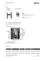
5.1.2 Incremental Mode
The incremental mode is used to set up a contactless encoder knob. In addition to the incremental
output, a push button output is available to integrate a contactless push-button.
Figure 4:
Using the board in incremental mode
Note: The grid and grid offset must be configured.
Note: To use the push-button functionality
6 AS5601 Configuration
All options to configure the AS5601 are shown below. To use the AS5601 in incremental mode for a
contactless rotary knob, the electrical signal must be aligned with the mechanical grid. As well the
push-button threshold must be configured for the mechanical setup.
6.1 Configuring the grid offset
An ideal mechanical grid and the electrical output are shown below in Figure 5 for a 3-bit encoder.
The transition of electrical signal should ideally be in the middle between two mechanical positions.
µC
+
-
A
B
Push

AS5601 Adapter Board
ams Eval Kit Manual, Confidential
Page 7
[v1-00] 2014-Jul-31
Document Feedback
Figure 5:
Aligning electrical and mechanical grid
Mechanical
position 1
Mechanical
position 2
Mechanical
position 8
Mechanical
position 3
Mechanical
position 4
Mechanical
position 6
Mechanical
position 5
Electrical
pos ition 1
Electrical
position 2
Electrical
position 3
Electrical
position 4
Electrical
pos ition 5
Electrical
pos ition 6
Electrical
pos ition 7
Electrical
position 8
Mechanical
position 7
If the electrical are mechanical grid are not aligned due to production, it can easily be configured
using a grid offset. The grid offset is calculated as shown below:
𝐺𝑟𝑖𝑑 𝑂𝑓𝑓𝑠𝑒𝑡 𝑆𝑒𝑔𝑚𝑒𝑛𝑡 = 𝑀𝑂𝐷(𝐶𝑢𝑟𝑟𝑒𝑛𝑡𝐴𝑛𝑔𝑙𝑒;
360°
2𝑛
) −
360°
2 ∗ 2𝑛
𝑛 … 𝑅𝑒𝑠𝑜𝑙𝑢𝑡𝑖𝑜𝑛
[
𝑏𝑖𝑡
]
𝐶𝑢𝑟𝑟𝑒𝑛𝑡𝐴𝑛𝑔𝑙𝑒 … 𝐶𝑢𝑟𝑟𝑒𝑛𝑡 𝑂𝑢𝑡𝑝𝑢𝑡 𝐴𝑛𝑔𝑙𝑒 [°]
Note: To configure the grid offset, the offset value in degrees must be converted and written into
the ZPOS register.
6.2 Configuring the grid push button threshold
The push-button threshold must be configured for optimal output. Therefor the threshold must be
determined and written into the PUSHTHR register.
The swing of the pushbutton function can be found by subtracting the AGC value of the pressed
button from the AGC value of the released button. The threshold value for the contactless
pushbutton should be half of the swing.
6.3 Permanently programming a configuration
A configuration is written using the I2C interface. The Burn_Setting command (Write 0x40 into
register 0xFF) can be used to permanently program a configuration.
6.3.1 Low Power Mode
Three low power modes are available to reduce the power consumption down to 1,5mA max.

AS5601 Adapter Board
ams Eval Kit Manual, Confidential
Page 8
[v1-00] 2014-Jul-31
Document Feedback
6.3.2 Hysteresis
A 1 to 3 LSB hysteresis of the 12-bit resolution can be enabled.
6.3.3 Slow Filter
The slow filter allows improving the output noise. The default setting for the Slow Filter is 16x and
can be reduced for faster response.
6.3.4 Fast Filter
The fast filter is active by selecting a Fast Filter Threshold. If the output value remains below the
threshold, the output noise is defined by the slow filter setting. When exceeding the threshold, the
output noise is defined from the fast filter for fast output response. The output noise is again defined
by the slow filter as soon as the output stays in the threshold again.
6.3.5 Watchdog
If the watchdog is active, the AS5601 automatically enters Low Power Mode 3 after one minute if
the output value stays within a threshold of 4 LSB.
7 Board Schematics, Layout and BOM
The schematic, layout and BOM of the adapterboard are shown below for reference.
7.1 Schematics
The schematic of the board is shown below in Figure 6.
Figure 6:
Adapterboard Schematic
1
1
2
2
3
3
4
4
D D
C C
B B
A A
Size
Date
Project Title
Revision
Sheet ofOriginator RPH
AS5601-AB-1.4A4 1
29.01.2014
3
3
1
2
3
4
not populated
Stiftleiste4_THMD
J3
1
2
3
4
Stiftleiste4_THMD
J2
not populated
VDD VDD
GND
SDA
SCL
GND
VREG
PUSH
B
A
A
B
10uF
Farnell
1833804
C2
C0805
100nF
Farnell
1740614
C1
C0603
GND
VDD
GND
V
R
E
G
J1
not populated
R3
NC
Note1: Supply
J1=OPEN: 5V
J1=CLOSED: 3.3V
Note2: Optional pull-ups
Note3:
Adapterboard can be used with AS5XXX-UCB-1.0
Note4:
AS5601 I2C Address is 0x36h
(Use 4pin I2C header in 3.3V mode)
VREG
A2
PUSH
A3
GND
A4
I2CLK
B2
I2CD
B3
B
B4
VDD
A1
A
B1
AS5601
U1
AS5601
R4
NC
S
C
L
S
D
A
VDD VDD

AS5601 Adapter Board
ams Eval Kit Manual, Confidential
Page 9
[v1-00] 2014-Jul-31
Document Feedback
7.2 Layout and Board Dimensions
The PCB layout is shown below in Figure 7.
Figure 7:
Adapterboard layout
7.3 Bill of Materials
The BOM of the pcb is below in Table 3.
Table 3:
Bill of Materials
Designator
Part
Footprint
Manufacturer
Comment
J1
Jumper / not populated
J2
Header / not populated
J3
Header / not populated
C1
C0603
0603
1
1
2
2
3
3
4
4
D D
C C
B B
A A
Size
Date
Project Title
Revision
Sheet ofOriginator RPH
AS5601-AB-1.4A4 1
29.01.2014
3
3
1
2
3
4
not populated
Stiftleiste4_THMD
J3
1
2
3
4
Stiftleiste4_THMD
J2
not populated
VDD VDD
GND
SDA
SCL
GND
VREG
PUSH
B
A
A
B
10uF
Farnell
1833804
C2
C0805
100nF
Farnell
1740614
C1
C0603
GND
VDD
GND
V
R
E
G
J1
not populated
R3
NC
Note1: Supply
J1=OPEN: 5V
J1=CLOSED: 3.3V
Note2: Optional pull-ups
Note3:
Adapterboard can be used with AS5XXX-UCB-1.0
Note4:
AS5601 I2C Address is 0x36h
(Use 4pin I2C header in 3.3V mode)
VREG
A2
PUSH
A3
GND
A4
I2CLK
B2
I2CD
B3
B
B4
VDD
A1
A
B1
AS5601
U1
AS5601
R4
NC
S
C
L
S
D
A
VDD VDD
1
1
2
2
3
3
4
4
D D
C C
B B
A A
Size
Date
Project Title
Revision
Sheet ofOriginator RPH
AS5601-AB-1.4A4 1
29.01.2014
3
3
1
2
3
4
not populated
Stiftleiste4_THMD
J3
1
2
3
4
Stiftleiste4_THMD
J2
not populated
VDD VDD
GND
SDA
SCL
GND
VREG
PUSH
B
A
A
B
10uF
Farnell
1833804
C2
C0805
100nF
Farnell
1740614
C1
C0603
GND
VDD
GND
V
R
E
G
J1
not populated
R3
NC
Note1: Supply
J1=OPEN: 5V
J1=CLOSED: 3.3V
Note2: Optional pull-ups
Note3:
Adapterboard can be used with AS5XXX-UCB-1.0
Note4:
AS5601 I2C Address is 0x36h
(Use 4pin I2C header in 3.3V mode)
VREG
A2
PUSH
A3
GND
A4
I2CLK
B2
I2CD
B3
B
B4
VDD
A1
A
B1
AS5601
U1
AS5601
R4
NC
S
C
L
S
D
A
VDD VDD

AS5601 Adapter Board
ams Eval Kit Manual, Confidential
Page 10
[v1-00] 2014-Jul-31
Document Feedback
Designator
Part
Footprint
Manufacturer
Comment
C2
C0805
0805
R3
Resistor / not populated
R0603
R4
Resistor / not populated
R0603
U1
AS5601
SOIC-8
amsAG
Smart Potentiometer IC
8 Evaluation tools
To configure the AS5601, no dedicated programmer is needed. For fast setup time the USB I&P
Box can be used to configure the AS5601 over I
2
C. The USB I&P Box can be ordered from the ams
webpage.
Additionally a magnet holder kit is available with consist of a distance block and a Knob which holds
the sensor magnet.
Please find the ordering information below in Table 4.
Table 4:
Ordering Information for Evaluation Tools
Ordering Code
Description
Image
USB I&P Box
To configure the AS5601
RMH05-DK-XX-1.0
Rotary Magnet Holder for
adapterboard

AS5601 Adapter Board
ams Eval Kit Manual, Confidential
Page 11
[v1-00] 2014-Jul-31
Document Feedback
9 Ordering & Contact Information
Ordering Code
Description
AS5601-SO_EK_AB
AS5601 Eval Kit Adapter Board
Buy our products or get free samples online at:
www.ams.com/ICdirect
Technical Support is available at:
www.ams.com/Technical-Support
Provide feedback about this document at:
www.ams.com/Document-Feedback
For further information and requests, e-mail us at:
ams_sales@ams.com
For sales offices, distributors and representatives, please visit:
www.ams.com/contact
Headquarters
ams AG
Tobelbaderstrasse 30
8141 Unterpremstaetten
Austria, Europe
Tel: +43 (0) 3136 500 0
Website: www.ams.com

AS5601 Adapter Board
ams Eval Kit Manual, Confidential
Page 12
[v1-00] 2014-Jul-31
Document Feedback
10 Copyrights & Disclaimer
Copyright ams AG, Tobelbader Strasse 30, 8141 Unterpremstaetten, Austria-Europe. Trademarks
Registered. All rights reserved. The material herein may not be reproduced, adapted, merged,
translated, stored, or used without the prior written consent of the copyright owner.
Demo Kits, Evaluation Kits and Reference Designs are provided to recipient on an “as is” basis for
demonstration and evaluation purposes only and are not considered to be finished end-products
intended and fit for general consumer use, commercial applications and applications with special
requirements such as but not limited to medical equipment or automotive applications. Demo Kits,
Evaluation Kits and Reference Designs have not been tested for compliance with electromagnetic
compatibility (EMC) standards and directives, unless otherwise specified. Demo Kits, Evaluation
Kits and Reference Designs shall be used by qualified personnel only.
ams AG reserves the right to change functionality and price of Demo Kits, Evaluation Kits and
Reference Designs at any time and without notice.
Any express or implied warranties, including, but not limited to the implied warranties of
merchantability and fitness for a particular purpose are disclaimed. Any claims and demands and
any direct, indirect, incidental, special, exemplary or consequential damages arising from the
inadequacy of the provided Demo Kits, Evaluation Kits and Reference Designs or incurred losses of
any kind (e.g. loss of use, data or profits or business interruption however caused) as a
consequence of their use are excluded.
ams AG shall not be liable to recipient or any third party for any damages, including but not limited
to personal injury, property damage, loss of profits, loss of use, interruption of business or indirect,
special, incidental or consequential damages, of any kind, in connection with or arising out of the
furnishing, performance or use of the technical data herein. No obligation or liability to recipient or
any third party shall arise or flow out of ams AG rendering of technical or other services.

AS5601 Adapter Board
ams Eval Kit Manual, Confidential
Page 13
[v1-00] 2014-Jul-31
Document Feedback
11 Revision Information
Initial version 1-00
Changes from 0-01 (2014-Jun-26) to current revision 1-00 (2014-Jul-31)
Page
Initial revision
Note: Page numbers for the previous version may differ from page numbers in the current revision.
-
 1
1
-
 2
2
-
 3
3
-
 4
4
-
 5
5
-
 6
6
-
 7
7
-
 8
8
-
 9
9
-
 10
10
-
 11
11
-
 12
12
-
 13
13


AMS AS5601AdapterBoard User guide
- Type
- User guide
- This manual is also suitable for
Ask a question and I''ll find the answer in the document
Finding information in a document is now easier with AI
Related papers
Other documents
-
Osram UG000345 Adapter Board User guide
-
Analog Devices MICROCONVERTER ADUC814-28TSSOP Reference guide
-
Braemar WF2000 Installation guide
-
Whirlpool AKT 616/IX User guide
-
LG HB9522A Owner's manual
-
Whirlpool AKT680/IXL User guide
-
-
-
-
Maytag MGC 3010 AAS Program Chart