Page is loading ...

Installation and Maintenance Instructions
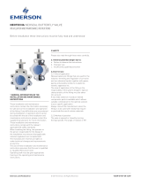
Sight Glass SG / Ball Check Valve KR
Emerson reserves the right to change the contents without notice NEOJV-0019-EN-1307
These installation and maintenance instructions must
be read in full and completely understood before the
installation!
Contents
1 General information on the installation
and maintenance instructions 1
2 Safety 1
3 Transport/Storage 2
4 Features 3
5 Identification 3
6 Installation 3
7 Commissioning 4
8 Notes on dangers during installation,
operation and maintenance 5
9 Operation 5
10 Servicing 5
11 Cause and remedy of
operating faults 5
12 Decommissioning 6
13 Disposal 6
14 Customer service 6
15 Validity of the Installation and
Maintenance Instructions 6
1. General information on the installation and maintenance instructions
These installation and maintenance instructions contain the information necessary for safe and
correct installation and operation of the valve in the prescribed manner. If any difficulties are
encountered during installation or operation which cannot be solved with the aid of the installation
and maintenance instructions, please contact the supplier/manufacturer for more information.
These installation and maintenance instructions comply with the relevant applicable EN safety
standards.
When installing the fitting, the operator or the person responsible for the design of the installation
must ensure that applicable national regulations are complied with.
The manufacturer reserves all rights to make technical changes and improvements at any time.
The use of these installation and maintenance instructions assumes that the user is qualified to
“Qualified Personnel” level.
Operating staff must be given appropriate training in the operating and maintenance instructions.
2. Safety
Please also read through these notes carefully.
2.1. Meaning of the symbols
This symbol in the operating instructions indicates dangers.
2.2. General potential danger due to:
a) failure to observe the instructions
b) improper use
c) insufficiently qualified personnel
2.3. Correct Use
2.3.1. Area of application
SG
Sight glasses equipped with 2 large borosilicate sight glasses and drip nozzle are valves which
facilitate the observation of highly corrosive, hot liquids and gases over a range from the smallest
quantity to large volume flows. The SG is suitable for vertical and horizontal mounting.
KR
Ball check valves with integral sight glass are valves which facilitate a controlled retention or
isolation of highly corrosive, hot liquids and gases. A special feature of the KR is the gas tight
seal. The soft elastomer seal inserted in the body guarantees a perfect shut off for gases. The
interchangeable soft seal can be supplied in various elastomers as far as Perfluorelastomer. The KR
is suitable for vertical and horizontal mounting. When mounted horizontally, the volume flow must
be high enough to press the ball into the seat via the guides.
SG / KR
All product-wetted components are manufactured in PFA and PTFE materials.
The materials used for components subject to pressure are GGG40.3, polyester coated and
borosilicate glass.
2.3.2. Method of Operation
SG
The medium can flow through without restriction in the working direction (direction of arrow)
and drip onto the drip nozzle. In the opposite direction, it is not possible to observe the smallest
quantity.
KR
The medium can flow through without restriction in the working direction (direction of arrow).
Inthe opposite direction, the ball closes the passage, as soon as sufficient pressure has built up
under the ball and pressed it into the ball seat.
NEOTECHA
www.valves.emerson.com

Installation and Maintenance Instructions
Sight Glass SG / Ball Check Valve KR
Emerson reserves the right to change the contents without notice page 2
2.3.4. Usage Restrictions
The product-wetted components must be classified
as resistant to the product to be conveyed. Refer
to appropriate literature or consult the manufacturer or distributor for advice.
2.3.5. Modification Prohibition
Mechanical modifications to the valves or the use of other manufacturers’ parts for repair
purposes are not permissible. Safety is not guaranteed if this requirement is disregarded.
Repair work must only be carried out by the manufacturer’s trained personnel.
2.3.6. Warning about foreseeable misuse
Valves and their accessories must not be misused as climbing aids.
2.3.7. Duty to comply with the instructions for operation, maintenance and servicing
These operating instructions are part of the delivery package and must be kept clean and
made accessible to the user.
2.4. Sources of Danger
2.4.1. Chemical external
The valve bodies are made from Spheroguss GGG40.3 coated with a 2-part polyester paint.
The coating can be attacked externally by strong solvents, leading to corrosion of the body.
If damage of this nature occurs, the effects on the environment should be investigated and
the damage to the coating made good.
2.4.2. Mechanical
Excessive oscillation and vibration should be avoided, to prevent the bolts loosening.
2.4.3. Electrical
If static charges can lead to explosions, the valve must be earthed by means of the
earthing accessory.
Alternative: Use valves with electrically conductive linings. Please contact your supplier!
2.4.4. Thermal
Due to the range of operating temperatures between -40°C and +200°C, surface
temperatures from -40° to +200°C can be present on the valve bodies. Suitable
precautions should be taken to protect against burns due to high or freezing temperatures.
Insulated gloves must be worn during installation and service work.
In case of fire, the mechanical strength of the PFA coatings is no longer guaranteed above
200°C.
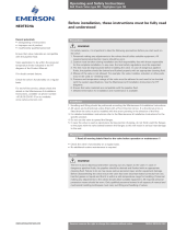
2.3.3. Performance Data
Pressure range : 16bar - 20Pa
Temperature range : see table
Nominal diameters : DIN PN16 DN 25 ANSI 150lbs 1”
DN40 1 1/2”
DN50 2”
DN80 3”
Test pressure : 1.5 x PN = 24bar
bar
20Pa
Pressure-Temperature diagram
Ball Check Valve Flow values
DN Kv Cv
25 17.5 20.5
40 32 37.5
50 51 60
80 128 50
Kv in m
3
/ hr Water Δp = 1 bar
Cv in USG / min Water Δp = 1 bar

25 1 68 90 80 160 75 48 63 10 115 85 4x14 4.6
40 1 1/2 88 118 105 200 92 65 80 12 150 110 4x18 9.1
50 2 120 134 125 230 107.5 82 100 15 165 125 4x18 12.2
80 3 138 196 190 310 145 150 175 25 200 160 8x18 25
Installation and Maintenance Instructions
Sight Glass SG / Ball Check Valve KR
Emerson reserves the right to change the contents without notice page 3
2.5. Requirements for the Operator
This means people who are familiar with the erection, installation, commissioning, operation and
maintenance of the product and have appropriate qualifications relating to their activities and
functions, such as e.g.:
- instruction in and duty to comply with all installation-related, regional and internal works
regulations and requirements
- training or instruction in accordance with the Safety Standards for personal care and use of
appropriate safety equipment and protective workgear, like e.g. personal protection equipment
(insulated gloves or similar), suitable for the operating conditions.
Furthermore, these people must have read and understood these instructions.
3. Transport/Storage
The valve is supplied with protective covers. Do not remove the protective covers until immediately
prior to installation. They protect the PFA surface from dust and mechanical influences.
3.1. Transport
- transport temperature -20°C to +65°C
- protect against external force (impact, shock, vibration)
- do not damage the coating
3.2. Storage
- storage temperature -20°C to +65°C, dry and dust-free.
- a drying agent or heating is required in damp storage areas to protect against condensation.
3.3. Handling prior to installation
- do not remove the protective covers until immediately prior to installation
- protect against the effects of weather, such as dampness (or else use a drying agent)
- proper treatment prevents damage
4. Features
Flange drillings : DIN 2501 PN16 or ANSI B16.5 Class 150
Face-to-face dimension : DIN 3202/T1/F1 and F17
Bolted joint : Hexagon bolts steel 8.8 galvanized *
KR variants : PTFE solid ball as standard
PTFE hollow ball, floating, for overflow safety device
PTFE ball with steel core for exhaust backwash
Sight glass : Borosilicate glass
Blank cover : Steel cover with virgin PTFE liner
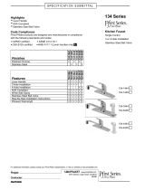
Sight glass
Parts list
Item Description Material
1 Body GGG 40.3 polyester coated
PFA lined
2 Cover GGG 40.3 polyester coated
3 Sight glass Borosilicate glass DIN 7080
4 Seal IT 150
5 Hexagon bolt Steel 8.8 galvanized
6 Hexagon nut Steel 8.8 galvanized
Dimensions and weights
DN
3
Weight
mm inches øA B E L
2
H øF øG S øD TK
3
Nxd
3
kg
2) Face-to face dimension according to DIN 3202/T1/F1 and F17
3) Flange drillings according to ANSI B16.5 Class 150 on request

25 1 68 90 80 160 75 48 63 30 10 115 85 4x14 4.6
40 1 1/2 88 118 105 200 92 65 80 46 12 150 110 4x18 9.1
50 2 120 134 125 230 107.5 82 100 56 15 165 125 4x18 12.2
80 3 138 196 190 310 145 150 175 90 25 160 200 8x18 25
Installation and Maintenance Instructions
Sight Glass SG / Ball Check Valve KR
Emerson reserves the right to change the contents without notice page 4
Ball check valve
Parts list
Item Description Material
1 Body GGG 40.3 polyester coated PFA lined
2 Cover GGG 40.3 polyester coated
3 Sight glass Borosilicate glass DIN 7080
3a
2)
Cover plate Steel KBL HII with PTFE liner
3b Cover Steel 37 with PTFE liner
4 Seal IT 150
5 Ball guide PTFE/glass
6 Solid ball Virgin PTFE
6a Hollow ball Virgin PTFE
6b Steel core ball Virgin PTFE/steel
7a
3)
Soft seat Perfluorelastomer (Kalrez
®
)
7b
3)
Soft seat FPM (Viton
®
) up to 140°C
7c
3)
Soft seat EPDM max. temp. 120°C
8 Hexagon bolt Steel 8.8 galvanized
8a Hexagon bolt Stainless steel A4-70
9 Hexagon nut Steel 8. galvanized
9a Hexagon nut Stainless steel A4
Dimensions and weights
DN
3
Weight
mm inches øA B E L
2
H øF øG øK S øD TK
3
Nxd
3
kg
2) Face-to face dimension according to DIN 3202/T1/F1 and F17
3) Flange drillings according to ANSI B16.5 Class 150 on request
Standard version:
Flange PN 16 DIN 2501
Face-to-face dimension DIN 3202/T1/F1 and F17 without soft seal
PTFE solid ball
Bolts in steel 8.8, nuts in steel 8, items 8/9
2) Cover plate, Item 3a, in steel K.Bl.H II can be supplied with certificate to DIN 50049-3.1 B
(ifglass is not permissible, for example).
3) If soft seal, Item 7, is required, please quote material a, b or c.
®RegisteredtrademarkofE.I.Dupont de Nemours SA
Glass cover
Blank cover
5. Identification
CE identification on the valve in accordance with Pressure Equipment Directive 97/23/EC > DN25
Additional identification on the valve in accordance with DIN 19, such as:
Manufacturer
Serial number
Year of manufacture
Country of manufacture
Equipment type
4.1. Installation position
The valve can be installed from a horizontal to a vertical position.
4.2. Sealing
KR
Soft seal and solid ball, installed vertically, provide a gas-tight shut off.
Without a soft seal, a pressure difference from 1.5 to 3 bar is required to achieve a drip tight shut
off, depending on the installation position.
Additional identification on the valve in accordance with DIN 19, such as:
DN, PN, manufacturer’s logos of the Neotecha AG company . The identification of the valve
body material is cast onto the valve.
CE-mark with 4-digit number
of notified body
Rating plate without CE mark Rating plate with CE mark

25 1 4 x M12 50
40 1 1/2 4 x M16 110
50 2 4 x M16 110
80 3 8 x M16 110
Installation and Maintenance Instructions
Sight Glass SG / Ball Check Valve KR
Emerson reserves the right to change the contents without notice page 5
6.2.1 Step-by-step installation
1. Remove the plastic protective covers.
2. Check the mounting flanges (damage, soiling).
3. Check that the distance between flanges matches the face-to-face dimension of the ball check
valve. Before installing the valve, spread the flanges apart sufficiently using a suitable tool.
4. Check that the direction of flow of the valve matches that of the pipeline system.
5. Slide the valve between the opened flanges.
6. Now insert the flange bolts through the adjusting holes.
7. Tighten the flange bolts hand-tight as the tool holding the flanges apart is gradually removed.
Make sure that the flanges remain correctly aligned.
8. Tighten all flange bolts in opposite pair sequence. Refer to following table for tightening torques.
Recommended torques
DN Bolts Torque
mm inches Nm
Recommended tightening torques (Nm) of bolted connections for installing isolation valves
6. Installation
6.1. Installation
6.1.1 Preparation for installation
The dimensions of the valves have been chosen so that the sight glasses / ball check valves can be
clamped between all current DIN and ANSI flanges. It should be noted here that valves designed
for a specific flange standard no longer fit other flanges.
The flanges must meet the following requirements:
- Cleaned and undamaged mating surface.
- The mating sections in the pipeline must be to the same connection standard as the valve which
is to be installed.
- The appropriate flange bolt hole arrangements in the various flange standards and diameters
allow the valve to be centered by passing the flange bolts through the holes in the flanges.
- The flange bolts must be centrally aligned in the holes in the valve flanges.
Flange packings are not required with flanges with flat sealing surfaces. Additional packings may
possibly be required with rubberized flanges.
6.1.2. Installation position
The valve can be installed from a horizontal to a vertical position.
(With the ball check valve, the ball is guided by 4 ribs)
6.2. Installation in the pipeline
With sight glasses / ball check valves, the flow direction has to be right.
SG
In the working direction (direction of arrow), the medium flows over the drip nozzle, which allows
the medium flowing through to be closely observed.
KR
The medium can flow through without restriction in the working direction (direction of arrow). In
the opposite direction, the ball closes the passage, as soon as sufficient pressure has built up under
the ball and pressed it into the ball seat.
The flow direction must be observed at the time of installation!
A sight glass / ball check valve is not a crowbar! Please do not use it to force the flanges apart, as
this would lead to damage to the PFA coating and seat. To avoid damage to the PFA coating, the
protective covers should only be removed immediately prior to installation.
It is not advisable to use the valve for positioning pipelines in new systems. Sparks which
occur during spot welding can damage the seat. Use adjusting pieces instead. Final
welding of the flange with the valve in position will lead to severe damage to the valve seat
due to the high temperature.
Always use all flange bolts, even on low pressure systems. The valve should never be pressurized if
one of the flange bolts is missing.

13. Disposal
Hand in the correctly cleaned valve to the
scrap material recycling plant.
Badly cleaned valves can cause severe
burning of the hands and other parts
of the body.
If the valve is passed on to a third
party, the manufacturer does
not guarantee the safety of the
equipment.
Installation and Maintenance Instructions
Sight Glass SG / Ball Check Valve KR
Emerson reserves the right to change the contents without notice page 6
7. Commissioning
7.1 General commissioning
Before commissioning, the information relating to material, pressure and temperature should be
checked against the installation diagram of the pipeline system.
Any debris left in the pipeline and valves (dirt, welding beads, etc.) will inevitably lead to leakage.
Before each commissioning of a new system or re-commissioning of a system after repair or
modification, it must be ensured that:
- all installation and assembly work has been completed in accordance with the
regulations!
- commissioning is only undertaken by “Qualified Personnel”
- the valve is in the correct operating position.
- new protective equipment is installed or existing protective equipment repaired.
8. Notes on dangers during installation, operation and maintenance
Safe operation of the valve is only guaranteed if it has been correctly installed, commissioned and
maintained by qualified personnel (see “Qualified Personnel”), taking into account the warning
information of these installation and maintenance instructions. In addition, compliance with the
general installation and safety regulations for the pipeline or plant construction, together with the
correct use of tools and protective equipment, must be ensured. The installation and maintenance
instructions must be strictly followed when any work is carried out on the valve or when handling
the valve. Non-observance can result in injuries or damage to property.
9. Operation
This valve must not be operated.
10. Servicing
No routine maintenance or lubrication is required. However, for systems with high temperatures,
an inspection for leakage at the flanges should be carried out shortly after installation. The different
coefficients of expansion and temperature expansions can cause settlement of the PFA. Tightening
the bolts once again will rectify this problem. This process may possibly have to be repeated
several times.
11. Cause and remedy of operating faults
If the valve function or operating action is faulty, a check should be made to ensure that the
assembly and installation work has been carried out and completed in accordance with the
installation and maintenance instructions.
The information relating to material, pressure, temperature and direction of flow should be
compared with the installation diagram of the pipeline system. Furthermore, a check should be
made on whether the installation conditions correspond to the technical data given in the data
sheet or on the rating plate.
The safety regulations must always be observed when troubleshooting.
12. Decommissioning
Removal of the valve for repair or servicing is often carried out carelessly, as the valve has to be
repaired or replaced in any case. However, it is recommended that the valve be removed with care,
without damaging the PFA, so that the possible cause of damage can be determined after removal.
Attention! Check that the pipe is depressurized and drained.
With corrosive, inflammable, aggressive or toxic media, flush out and ventilate the pipeline
system.
1. Only allow assembly work to be carried out by qualified personnel (see Section 2.5).
2. Loosen all flange bolts and withdraw them until the valve can be removed.
3. Spread the flanges apart using a suitable tool and withdraw the valve.
6.2.2. Final checks
- checking the operation of the valve
- cleaning and flushing the pipeline before the first closure.
15. Validity of the Installation and
Maintenance Instructions
These installation and maintenance
instructions are valid from 01.09.2001 until the
next revision.
14. Customer service
For further information or technical advice,
please contact:
Neotecha A.G.
Etzelstrasse 37-39
CH-8634 Hombrechtikon / Switzerland
Telephone: +41 (0) 55 - 254 41 41
Fax: +41 (0) 55 - 254 41 00
/