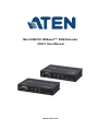
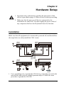
ATEN CE611 Mini USB DVI HDBaseT KVM Extender extends DVI, RS-232 serial, and USB 2.0 signals up to 328 feet (100 meters) over a single Cat5e/6 cable. Supporting resolutions up to 1920 x 1200, the CE611 ensures superior video quality. Ideal for control rooms, shopping malls, industrial kiosks, and medical facilities, the CE611 is also perfect for data syncing.
ATEN CE611 Mini USB DVI HDBaseT KVM Extender extends DVI, RS-232 serial, and USB 2.0 signals up to 328 feet (100 meters) over a single Cat5e/6 cable. Supporting resolutions up to 1920 x 1200, the CE611 ensures superior video quality. Ideal for control rooms, shopping malls, industrial kiosks, and medical facilities, the CE611 is also perfect for data syncing.


-
 1
1
-
 2
2
-
 3
3
-
 4
4
-
 5
5
-
 6
6
-
 7
7
-
 8
8
-
 9
9
-
 10
10
-
 11
11
-
 12
12
-
 13
13
-
 14
14
-
 15
15
-
 16
16
-
 17
17
-
 18
18
-
 19
19
-
 20
20
-
 21
21
-
 22
22


ATEN CE611 Mini USB DVI HDBaseT KVM Extender extends DVI, RS-232 serial, and USB 2.0 signals up to 328 feet (100 meters) over a single Cat5e/6 cable. Supporting resolutions up to 1920 x 1200, the CE611 ensures superior video quality. Ideal for control rooms, shopping malls, industrial kiosks, and medical facilities, the CE611 is also perfect for data syncing.
Ask a question and I''ll find the answer in the document
Finding information in a document is now easier with AI