Page is loading ...

Please read and save these instructions. Read carefully before attempting to assemble, install, operate or maintain the product
described. Protect yourself and others by observing all safety information. Failure to comply with instructions could result in
personal injury and/or property damage! Retain instructions for future reference.
Operating Instructions and Parts Manual DG201800CD
Unpacking
When unpacking this product,
carefully inspect for any damage that
may have occurred during transit.
General Safety
Information
This manual contains information that is
very important to know and understand.
This information is provided for SAFETY
and to PREVENT EQUIPMENT PROBLEMS.
To help recognize this information,
observe the following symbols.
Danger
indicates
an imminently hazardous situation which,
if not avoided, will result in death or
serious injury.
Warning
indicates a
potentially hazardous situation which, if
not avoided, could result in death or
serious injury.
Caution
indicates
a potentially hazardous situation
which, if not avoided, may result in
minor or moderate injury.
Notice
indicates
important information, that if not
followed, may cause damage to tool.
The following safety precautions must
be followed at all times along with any
other existing safety rules.
1. Read all manuals included with this
product carefully. Be thoroughly
familiar with the controls and the
proper use of the equipment.
2. Only persons well acquainted with
these rules of safe operation should
be allowed to use this tool.
IN722500AV 8/07© 2007 Campbell Hausfeld/Scott Fetzer
See Warranty on page 10 for important information about commercial use of this product.
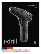
2-Finger
Trigger
Adjustable
Clutch Collar
Keyless Chuck
Horizontal
Barrel Level
Battery
Indicator
Magnetic
Tray
High/Low
Gear Switch
Vertical
Target
Level
Forward/Reverse
Button and
Trigger Lock
Bit Storage
Soft Grip
REMINDER: Keep your dated proof of purchase for warranty purposes!
Attach it to this manual or file it for safekeeping.
Product Voltage
No-Load Max. Capacity
Battery Pack Battery charger
speed of chuck
DG201800CD 18 V dc
0-360/0-1030 Ø 3/8"
DG024900AV DG024700AV
min
-1
Ø 10 mm
Cordless Drill/Driver
and Charger
BUILT TO LAST
For parts, product & service information
visit www.chpower.com
Battery
Pack
Release
Model DG201800CD

General Power Tool
Safety Warnings
Read all
safety
warnings and all instructions. Failure
to follow the warnings and
instructions may result in electric
shock, fire and/or serious injury.
SAVE ALL WARNINGS AND
INSTRUCTIONS FOR FUTURE
REFERENCE.
The term “power tool” in the warnings
refers to your battery-operated
(cordless) power tool.
1) Work area safety
a) Keep work area clean and
well lit. Cluttered or dark areas
invite accidents.
b) Do not operate power tools
in explosive atmosphere,
such as in the presence of
flammable liquids, gases or
dust. Power tools create sparks
which may ignite the dust or
fumes.
c) Keep children and bystanders
away while operating a
power tool. Distractions can
cause you to lose control.
2) Electrical Safety
a) Power tool plugs must match
the outlet. Never modify the
plug in any way. Do not use
any adapter plugs with
earthed (grounded) power
tools. Unmodified plugs and
matching outlets will reduce risk
of electric shock.
b) Avoid body contact with
earthed or grounded
surfaces, such as pipes,
radiators, ranges and
refrigerators. There is an
increased risk of electric shock if
your body is earthed or
grounded.
c) Do not expose power tools to
rain or wet conditions. Water
entering a power tool will
increase the risk of electric shock.
d) Do not abuse the cord. Never
use the cord for carrying,
2
Operating Instructions
pulling or unplugging the
power tool. Keep cord away
from heat, oil, sharp edges or
moving parts. Damaged or
entangled cords increase the
risk of electric shock.
e) When operating a power tool
outdoors, use an extension
cord suitable for outdoor
use. Use of a cord suitable for
outdoor use reduces the risk of
electric shock.
f) If operating a power tool in a
damp location is
unavoidable, use a residual
current device (RC) protected
supply. Use of an RCD reduces
the risk of electric shock.
g) Hold power tools by
insulated gripping surfaces
when performing an
operation where the cutting
tool may contact hidden
wiring or its own cord.
Contact with a “live” wire will
make exposed metal parts of the
tool “live” and shock the
operator.
h) If an extension cord is used,
make sure:
• That the size of the cord is at
least as specified in the chart
titled “Minimum Wire Size
(AWG) of Extension Cord for
Battery Charger.”
• That the pins on the plug of
the extension cord are the
same number, size, and shape
as those on the plug of the
charger.
• That the extension cord is
properly wired and in good
electrical condition.
• That the extension cord, if it is
to be used outdoors, is
marked with the suffix “W-A”
or “W”. This should follow
the cord type designation (e.g.
SJTW-A). Such a designation
indicates that it is acceptable
for outdoor use.
i) Recharge this battery-
operated tool only with the
charger specified for the
battery. A charger suitable
for one type of battery can
create a risk of fire when
used with another battery.
j) Use this battery-operated
tool only with its designated
battery pack. Use of any
other batteries may create a
risk of fire.
3) Personal safety
a) Stay alert, watch what you
are doing and use common
sense when operating a
power tool. Do not use a
power tool while you are
tired or under the influence
of drugs, alcohol or
medication. A moment of
inattention while operating
power tools may result in serious
personal injury.
b) Use personal protective
equipment. Always wear eye
protection. Protective
equipment such as dust mask,
non-skid safety shoes, hard hat,
or hearing protection used for
appropriate conditions will
reduce personal injuries.
c) Prevent unintentional
starting. Ensure the switch is
in the off-position before
connecting to power source
and/or battery pack, picking
up or carrying the tool.
Carrying power tools with your
finger on the switch or
energizing power tools that have
the switch on invites accidents.
Length of Cord in Feet 25 50 100 150
AWG Size of Cord 18 18 18 16
Minimum Wire Size (AWG) of Extension Cord for Battery Charger

3
DG201800CD
General Power Tool
Safety Warnings
(Continued)
d) Remove any adjusting key or
wrench before turning the
power tool on. A wrench or a
key left attached to a rotating
part of the power tool may
result in personal injury.
e) Do not overreach. Keep
proper footing and balance
at all times. This enables better
control of the power tool in
unexpected situations.
f) Dress properly. Do not wear
loose clothing or jewelry.
Keep your hair, clothing and
gloves away from moving
parts. Loose clothes, jewelry or
long hair can be caught in
moving parts.
g) If devices are provided for
the connection of dust
extraction and collection
facilities, ensure these are
connected and properly used.
Use of dust collection can reduce
dust-related hazards.
h) CALIFORNIA PROPOSITION 65
You can create dust
when you cut,
sand, drill or grind
materials such as
wood, paint, metal,
concrete, cement,
or other masonry. This dust often
contains chemicals known to
cause cancer, birth defects, or
other reproductive harm. Wear
protective gear.
i)
This product or its power cord
contains lead, a chemical known
to the State of California to
cause cancer and birth defects or
other reproductive harm. Wash
hands after handling.
j) Some wood contains
preservatives which can be
toxic. Take extra care to
prevent inhalation and skin
contact when working with
these materials. Request and
follow all safety information
available from your material
supplier.
k)
Do not misuse this product.
Excessive exposure to vibration,
work in awkward positions, and
repetitive work motions can
cause injury to hands and arms.
Stop using any tool if discomfort,
numbness, tingling, or pain
occur, and consult a physician.
l) Always work in a well-
ventilated area. Wear an
OSHA-approved dust mask.
m) Keep hands away from
rotating parts.
n) Use clamps or another
practical way to secure the
workpiece to a stable
platform. Never hold work in
your hand, lap, or against
other parts of your body
when drilling.
o) Before using the battery
charger, read all instructions
on the charger, battery, and
product.
p) Do not attempt to
disassemble the battery or
remove any component
projecting from the battery
terminals. Fire or injury may
result.
4) Power tool use and care
a) Do not force the power tool.
Use the correct power tool for
your application. The correct
power tool will do the job better
and safer at the rate for which it
was designed.
b) Do not use the power tool if
the switch does not turn it on
and off. Any power tool that
cannot be controlled with the
switch is dangerous and must be
repaired.
c) Disconnect the plug from the
power source and/or the
battery pack from the power
tool before making any
adjustments, changing
accessories, or storing power
tools. Such preventive safety
measures reduce the risk of
starting the power tool
accidentally.
d) Store idle power tools out of
the reach of children and do
not allow persons unfamiliar
with the power tool or these
instructions to operate the
power tool. Power tools are
dangerous in the hands of
untrained users.
e) Maintain power tools. Check
for misalignment or binding
of moving parts, breakage of
parts and any other condition
that may affect the power
tool’s operation. If damaged,
have the power tool repaired
before use. Many accidents are
caused by poorly maintained
power tools.
f) Keep cutting tools sharp and
clean. Properly maintained
cutting tools with sharp cutting
edges are less likely to bind and
are easier to control.
g) Use the power tool,
accessories and tool bits etc.
in accordance with these
instructions, taking into
account the working
conditions and the work to
be performed. Use of the
power tool for operations
different from those intended
could result in a hazardous
situation.

4
General Power Tool
Safety Warnings
(Continued)
h) When the battery pack is not
in use, keep it away from
metal objects such as paper
clips, coins, keys, nails,
screws, or the like so there is
no risk of the battery
terminals being connected
(that is, “shorted”) together.
Shorting the battery terminals
together may cause sparks,
burns, a fire, a shock, or damage
to the battery.
i) Do not use if the chuck jaws
or other parts are cracked or
worn.
j) Verify the drill’s rotation
before starting to drill/drive,
so that it is correct for the
operation being performed.
k) Do not use the drill as a
router or try to elongate or
enlarge holes by twisting the
drill. Drill bits may break and
cause injury.
l) Each drill is equipped with a
chuck capable of handling
bits up to a certain size. For
the DG2019 drill, bits with
shaft diameters greater than
3/8" [10mm] should not be
used.
m) Ensure the switch is in the
off position before inserting
the battery pack. Inserting the
battery pack into power tools
that have the switch on invites
accidents.
n) Recharge the battery pack
only with the charger
supplied with this tool. A
charger that is suitable for one
type of battery pack may create
a risk of fire when used with
another battery pack.
o) Use this drill only with the
supplied battery pack or the
recommended replacement
pack as specified by the
manufacturer. Use of any other
battery packs may create a risk
of injury or fire.
p) Charge the battery pack in a
well-ventilated area. Do not
allow any object to cover the
charger and/or battery pack
while charging.
q) Do not operate the battery
charger if its plug or cord has
been damaged. If these
components are damaged,
have them replaced
immediately by a qualified
repair person.
r) Do not operate the charger if
it has been dropped, received
a sharp blow, or otherwise
been damaged. If damaged,
have it serviced by a
qualified repair person.
s) Make sure the cord is located
so that it will not be stepped
on, tripped over, or
otherwise subjected to
damage or stress.
t) Do not store the battery
charger or battery pack in
locations where the
temperature may reach or
exceed 120°F [49°C], such as
in a metal tool shed or in a
car during the summer. This
can lead to deterioration of
these components.
u) For optimal charging of the
battery pack, charging should
take place in temperatures
ranging from 32°F to 86°F
[0°C to 30°C]. Charging the
battery pack outside this
recommended range can
adversely affect the battery’s
performance.
v) Do not charge the battery
pack in damp or wet
conditions.
w) Do not charge the battery
pack if it feels hot to the
touch. Wait for it to cool.
x) Since this tool is equipped
with nickel-cadmium
batteries, the battery pack
must be recycled or disposed
of in an environmentally
sound manner. Check with
your county’s Public Works
Department for information
on recycling nickel-cadmium
batteries. Prior to disposal,
insulate the metal battery
pack terminals by covering
them securely with heavy
insulating tape in order to
prevent any possible
shorting.
y) Do not incinerate the
battery pack as it may
explode in a fire.
5) Service
Have your power tool
serviced by a qualified repair
person using only identical
replacement parts. This will
ensure that the safety of the
power tool is maintained.
Tool Operation
The power source for this drill comes
from the supplied battery packs. It is
important that the user understand
the following in order to get the most
of the battery pack and the battery
charger.
Installing / Removing the Battery
Pack to / from the Drill
• In order to install the battery pack to
the drill, insert the tower potion of
the pack into the drill handle. Push
the battery pack until you hear the
pack latching to the drill.
• In order to remove the battery pack
from the drill, depress both of the
circular (ribbed) buttons on the pack
and then pull the pack from the
drill.
Operating Instructions

Tool Operation
(Continued)
Charging the Battery Pack
Installing/Removing the Battery Pack
from the Battery Charger
• The battery pack is designed
so that it can only fit into the
charger in one orientation,
therefore, there is no reason
to force the pack into the
charger. To install the battery
pack in the charger, insert the
tower end of the pack into
the charger. The protruding
rib on one side of the battery
pack should be aligned with
the notch in the battery
charger. Once this alignment
is done, lightly push the
battery pack until it bottoms
out in the charger.
• To remove the battery pack
from the charger, simply pull
the battery straight out of the
battery charger.
Initial Charging
Before using this drill for the first
time, charge the battery fully. This
can be done by first plugging the
battery charger into a 120V (60 Hz)
power supply and then inserting the
battery fully into the charger, noting
that the battery pack rib is oriented
so that it fits into the notch of the
battery charger. When the battery
pack is pressed slightly so that the
pack bottoms out in the charger, the
red charger light should then
illuminate. This indicates that the
battery is being charged. Once the
pack is fully charged, the green
charger light should illuminate. This
charging process should take
approximately one hour.
Additional Charging Notes
• During normal use, the
battery pack will eventually
lose its capacity and when this
happens, there will be a
noticeable difference in the
drill’s performance. It is at this
point that the battery pack
approaches its discharged
state and needs to be
recharged. If the pack is
warm-hot to touch, let the
battery pack cool down
before placing it in the
charger. This will allow the
pack to accept a full charge
whereas it might not do so if
inserted in the charger in an
elevated-temperature state.
• With the type of battery
supplied with this drill, that is
Ni-Cd or Nickel Cadmium type,
it is best that they are charged
when close to its discharged
state. This is the point where
there is a noticeable
difference in the performance
of the drill. If the pack is
placed in the charger before it
reaches this state, there is a
possibility that the
capacity/life of the battery
pack may not be optimized. It
is also important to note that
a battery pack should not be
discharged past the
performance-noticeable state
mentioned above as this
might irreversibly damage the
battery pack.
• Lastly in order to get the most
out of your battery pack, it is
highly recommended that the
packs not remain in the
charger for more than 3
hours. So once fully-charged
(indicated by the green
charger light illuminating), it
is best to remove the battery
pack at or near that point.
Forward/Reverse Button
This drill is equipped with a
forward/reverse (red) button which is
used to change the direction of
rotation of the drill chuck/bit. It is
recommended that the user check the
direction of rotation prior to
performing the work. If the FWD
button is firmly depressed from the
right side of the drill when the user
holds it, the rotation of the drill will be
in the forward direction, or clockwise
when viewing the chuck from a user
viewpoint. This is the recommended
rotational direction for drilling holes
or driving screws. By firmly depressing
the REV button (on the left side of the
tool), the rotation of the drill will be
counterclockwise. This direction of
rotation is recommended for removing
screws. It is also useful if a drill bit has
been stuck when drilling in the
forward direction.
Do not attempt to change the rotation
unless the drill chuck is completely
stopped. Failure to do so can damage
the tool.
If the FWD/REV button is centered in
the drill housing, that is, not fully
depressed to either side, then the
switch trigger should be locked in the
“OFF” position.
Variable-Speed Switch Trigger
This drill is equipped with a variable-
speed switch. By applying more
pressure to the (red) switch trigger, the
speed of the drill will increase.
Releasing pressure will slow the drill.
This accurate speed control allows the
user to slowly start drilling a hole
without center-punching, or slowly
start driving screws, before increasing
the operational rate.
5
Charger and Battery
DG201800CD

Tool Operation
(Continued)
Two-speed gearing
In addition to the variable-speed
switch, this drill is also equipped with a
two-speed gearbox. The low gear
(setting “1”) provides high-torque and
slower drilling speeds for heavy-duty
work or for driving screws. The high
gear (setting “2”) provides faster
speeds which is particularly useful for
drilling into softer materials. To
change to the high-speed setting, push
the (red) speed selector knob fully
forward. For the low-speed setting,
move the speed-selector knob fully
toward the rear of the drill. It is
important that this knob be positioned
fully forward or fully back, anywhere
in between can cause damage to the
drill.
If the drill has been actuated but the
chuck is not rotating, fully release
pressure on the switch actuator and
then slide the gear actuator to its
desired setting.
Electrical Brake
This drill is equipped with an electrical
brake which is used to stop the chuck
quickly. This is useful when the job
calls for repetitive driving or removal
of screws. This is activated by merely
releasing the switch actuator while the
drill is rotating. When the electric
brake is actuated, it is common to see
momentary arcing within the drill
itself.
Adjustable Clutch
This drill/driver features 16 clutch
settings. Output torque will increase as
the clutch collar is rotated from 1 to
15. The drill bit position locks the
clutch in order to permit heavy-duty
drilling and driving work. It also allows
bits to be changed quickly and easily in
the keyless chuck. This adjustable
clutch is particularly useful when
driving screws. A lower clutch setting
will ratchet sooner than a high-clutch
setting, that is, it will limit how far a
screw is driven. When driving screws, it
is best to start at a lower clutch setting
and adjust this collar upwards until the
screw is set to the desired depth.
Bubble Levels
This drill/driver is equipped with two
bubble levels in order to make it easier
for the user to drill squarely. There is a
horizontal level on top of the drill and
in order to drill/drive horizontally, the
bubble on this particular level should
be centered between the two level
lines. For those jobs where the user
wants to drill straight up-and-down,
there is another level on the back side
of the drill for that particular purpose.
For vertical drilling, the center of the
bubble should be at the intersection of
the crosshairs.
Magnetic Screw Holder
This drill/driver is equipped with a
magnet on top of the drill, underneath
the horseshoe magnet symbol. This is
useful for storing screws when doing
repetitive work.
Battery Fuel Gauge Indicator Lights
This drill/driver is equipped with a
battery fuel gauge. This is positioned
on top of the drill and is composed of
three green lights and a black button.
In order to check the state of the
battery pack, depress the black button
when the drill is OFF. If three of the
green lights illuminate, this indicates a
fully-charged or nearly charged
battery pack. If only one green light
illuminates, the battery pack is nearing
that point where it should be
recharged. If no lights illuminate, the
battery pack needs to be recharged.
Inserting / Removing Bits
• In order to clamp a bit in the drill,
move the FWD/REV button to its
center position and rotate the clutch
ring to the drill bit symbol. Rotate
the chuck sleeve counterclockwise
(when viewing from the chuck end)
until the chuck jaws are opened
slightly more than the diameter of
the bit to be inserted. Insert a clean
bit up to the drill bit flutes (for
smaller bits) or as far as it will go for
large bits. Close the chuck by
rotating the chuck sleeve clockwise
and securely tighten by hand.
• In order to remove the bit from the
drill, move the FWD/REV button to
its center position and rotate the
clutch ring to the drill bit symbol.
Rotate the chuck sleeve clockwise
(when viewing from the chuck end)
until the chuck jaws are opened
slightly more than the diameter of
the bit and then remove the bit.
Do not
use the
power of the drill to loosen or tighten
the bit while holding the chuck. The
spinning chuck will cause friction burn
and hand injury.
Phillips and slotted screw driver bits
are included onboard with this drill
and can be easily installed as
previously noted. These are particularly
useful for driving/removing screws.
General Drilling
Instructions
Safety
glasses
must be worn during drilling
operations.
Always
be alert
and brace yourself against the twisting
action of the drill. A firm hold should
always be administered when drilling.
Failure to do so may result in bodily
injury.
• Adjust the drill’s chuck collar so that
arrow on the drill body points to the
drill bit symbol on the chuck collar.
• Set the speed selector to the desired
setting. Typically the harder the
material being drilled into, the
slower the recommended speed.
• Insure that the drill bit is securely
gripped in the chuck.
• Make sure that the FWD button is
fully depressed. This should make
the drill rotate in the forward
direction, that is, clockwise as
viewed from the user’s vantage
point.
6
Operating Instructions

General Drilling
Instructions
(Continued)
• Make
sure that the workpiece is secured
This might entail clamping it in a vise
or held securely by other clamping
means A loose workpiece may spin
and cause bodily injury.
• Locate the center for the hole to be
drilled and using a center punch,
make a small dent in the workpiece.
• Place the tip of the drill bit in this
dent, hold the drill square to the
workpiece, apply steady pressure,
and actuate the drill’s switch.
•
Continue to apply steady, even
pressure while drilling. Applying too
much pressure may cause the drill bit
to overheat and/or break, resulting
in bodily injury or damaged drill bits
Too little pressure will keep the bit
from cutting into the workpiece.
• If the drill stalls or becomes jammed
in the hole, release the switch
trigger immediately Do not keep
actuating the switch trigger in the
forward direction in order to free
the bit from its jammed condition,
for this will damage the motor
Remove the drill bit from the
workpiece and determine the cause
of stalling or jamming before
beginning again. If it is troublesome
to remove the bit from the
workpiece, then fully-depress the
REV button and actuate the switch
to remove the bit. Then fully depress
the FWD button before resuming
the drilling operation.
• When the bit is at the point where it
nearly breaks through the material
being drilled, reduce the pressure on
the drill in order to avoid splintering
the wood or stalling in a metal
workpiece.
• When the drill bit has completely
penetrated the workpiece and is
spinning freely, withdraw it from
the workpiece while the motor is
still running, and then turn off the
drill.
Drilling Wood
In addition to the guidelines given in
the General Drilling Instructions, the
following also apply:
• When drilling into softer wood,
higher speed settings are generally
used.
• When drilling into wood using a
twist drill bit, frequently withdraw it
from the hole in order to clear away
chips which build up in the flutes.
This helps prevent overheating and
burning the material while speeding
up the drilling process.
• If a backing block is used to keep the
back of the workpiece from
splintering, clamp it securely in
place. If a backing block is not use
with spade bits or hole saws, ease up
the pressure exerted on the drill as
soon as the bit point breaks through
the workpiece. Remove the bit and
using the breakthrough hole,
reposition the bit on the opposite
side of the workpiece and finish the
drilling operation.
Drilling in Metal
In addition to the guidelines given in
the General Drilling Instructions, the
following also apply:
• Use only good quality, sharp, high-
speed drill bits when drilling into
metal.
• When drilling into metal, lower
speed settings are generally used.
The harder the material, the slower
the drilling speed should be.
• Start drilling with a slow speed and
gradually increase the speed as the
drill cuts.
• When drilling a large hole, it is
easier to first drill a smaller (pilot)
hole and then enlarge it to the
required size.
• The use of a lubricant, such as oil, on
the drill point helps to keep the bit
cool, increases the drilling action,
and prolongs bit life.
7
DG201800CD

General Driving
Screws Instructions
Safety
glasses
must be worn during driving
operations.
Always
be alert
and brace yourself against the twisting
action of the drill. A firm hold should
always be administered when driving
screws. Failure to do so may result in
bodily injury.
• Drill a pilot hole of a size
recommended by the screw
manufacturer prior to driving the
screws in place.
• Adjust the drill’s chuck collar so that
arrow on the drill body points to the
desired torque setting. A lower
number will cause the drill to ratchet
sooner, that is, it will not drive the
screw into the workpiece as far as if
a higher clutch collar setting is used.
• Set the speed selector to the low
speed “1” setting.
• Install the proper screwdriver bit and
insure that this bit is securely
gripped in the chuck.
• Make sure that the FWD button is
fully depressed. This should make
the drill rotate in the forward
direction, that is, clockwise as
viewed from the user’s vantage
point.
•
Make
sure that the workpiece is secured.
This might entail clamping it in a vise
or held securely by other clamping
means. A loose workpiece may spin
and cause bodily injury.
• Using one’s fingers, place the tip of
the screw in the pilot hole and turn
clockwise so as to start the screw
squarely.
• Place a properly-sized screwdriver bit
on the screw and while exerting
pressure on the drill, actuate the
switch trigger to drive the screw in
place. It is important that the screw
be driven squarely from the start, so
a constant square pressure should be
administered in order to drive the
screw properly in place. If too little
pressure is put on the drill during
this driving operation, the
screwdriver bit may not be retained
in the screw head- this could
damage or strip the end of the
screw.
• As soon as the screw has been
seated, release the switch trigger
and lift the screwdriver from the
screw head. If the drill ratchets
before driving the screw to the
desired depth, remove the drill from
the screw head and increase the
clutch collar setting. Then repeat the
driving process.
• A lubricant, such as soap or wax,
may be used on screw threads for
ease of driving. This is particularly
important when dealing with hard
wood.
• Screws are typically comprised of a
threaded section, a shank section in
which there are no threads, and the
screw head. Sometimes it is
advantageous to drill
holes/countersinks in one operation
and there are different combination
bits (e.g. pilot drill/shank, pilot drill
bit/countersink, etc.) available at
local supply houses for doing these
combinations.
Driving Wood Screws
In addition to the guidelines given in
the General Driving Instructions, the
following also apply:
• Prior to driving a wood screw in
place, it is recommended that a pilot
hole (and shank hole if necessary) be
first drilled. See the table below for
recommendations when using
common screw sizes.
Driving Self-tapping Screws
In addition to the guidelines given in
the General Driving Instructions, the
following also apply:
• Prior to driving the self-tapping
screw in place, drill a pilot hole of
the recommended size by the
manufacturer. Place the tip of the
screw in the pre-drilled hole and
while gently holding the screw
square, slowly start driving the
screw. Once it has properly started,
discontinue holding the screw
threads and finish driving the screw.
As soon as the screw is seated,
release the switch trigger and lift
the drill from the screw head.
Driving Machine Screws
In addition to the guidelines given in
the General Driving Instructions, the
following also apply:
• Prior to driving the machine screw in
place, drill and tap a hole of the
recommended size by the
manufacturer. Start the threads of
the screw in the tapped hole by
hand and once squarely in place,
discontinue holding the screw and
then start to slowly drive the screw
with the driver. Once the screw has
been fully seated, release the switch
trigger and lift the drill from the
screw head.
8
Operating Instructions
RECOMMENDATIONS FOR DRIVING WOOD SCREWS
SCREW PILOT DRILL DIAMETER SHANK SCREWDRIVER BIT TIP
SIZE (FOR SOFT WOOD) (FOR HARD WOOD) PILOT HOLE SLOTTED BIT PHILLIPS BIT
#6 1/16" (0.063") 5/64" (0.078") 9/64" (0.141") 3/16" #2
#8 5/64" (0.078") 3/32" (0.094") 11/64" (0.172") 1/4" #2
#10 3/32" (0.094") 7/64" (0.109") 3/16" (0.188") 5/16" #2 OR #3*
#12 7/32" 0.219") 1/8" (0.125") 7/32" (0.219") 3/8" #3
* Some head styles in this size take a #2 Phillips bit and others #3.

General Driving
Screws Instructions
(Continued)
Removing Screws
In order to remove a screw from a
workpiece, use the following steps:
• Set the clutch adjusting collar to its
highest setting and set the speed
selector to its lowest "1" setting.
• Install the proper screwdriver bit
into the drill’s chuck.
• Fully depress the REV button.
• Place the screwdriver bit in the screw
head and with enough pressure
exerted on the drill so that it doesn’t
jump out of the screw head, start
the drill to remove the screw.
Maintenance
Cleaning
All plastic parts should be cleaned with
a soft damp cloth. NEVER use solvents
to clean plastic parts. They could
dissolve or otherwise damage the
material.
Failure to Start
Should your tool fail to start, make
sure the battery pack is charged and
installed in the drill.
Battery Service
The battery pack supplied with this
drill will self-discharge and lose some
of its capacity over time. Therefore, if
it is stored unused for a long period of
time, then it may require recharging
before use. In order to get the most
out of your batteries, it is
recommended that the pack be
recharged every 2-3 months and when
doing so, remove the pack from the
charger after 2-3 hours of charging.
Removing/Replacing the Chuck
If there is a need to replace the chuck,
use the following steps to do so:
• Remove the battery pack from the
drill.
• Rotate the clutch collar until its drill
bit symbol aligns with the arrow on
the top of the drill housing.
• Open the chuck jaws fully by
unscrewing the chuck sleeve
counterclockwise (when viewing the
chuck from its end).
• Locate the left-handed screw inside
the chuck and with the proper
screwdriver bit and remove this
screw by turning it clockwise.
• Insert the short arm of a 3/8" hex
key or Allen wrench into the chuck
and tighten the jaws of the chuck on
the flats of this wrench.
• With a hammer or the like, strike the
long arm of the wrench sharply so
that the chuck will turn
counterclockwise.
• Once the chuck has been loosened,
remove the wrench and unscrew the
chuck from its spindle.
• To replace the chuck with another
one, reverse the steps noted above.
Always keep the spindle threads,
chuck threads, and securing screw
free of debris.
Service
Tool
service
must be performed only by qualified
repair personnel and by an
AUTHORIZED SERVICE CENTER. Service
or maintenance performed by
unqualified personnel could result in a
risk of injury.
For information regarding the
operation or repair of this product,
please call 1-800- 424-8936.
9
For Replacement Parts or Technical Assistance, call 1-800-424-8936
Please provide following information:
- Model number
- Serial number (if any)
- Part description and number as shown in parts list
Part
Description Number
Address any correspondence to:
Campbell Hausfeld
Attn: Parts Department
100 Production Drive
Harrison, OH 45030 U.S.A.
Charger – 18V DG024700AV
Battery Pack – 18V DG024900AV
Chuck – 3/8" DG029900AV
Set Screw SX173400AV
DG201800CD

Limited Warranty
1. DURATION: One (1) Year from the date of purchase by the original purchaser on drill. Batteries are warranted for one
(1) year.
2. WHO GIVES THIS WARRANTY (WARRANTOR): Campbell Hausfeld / Scott Fetzer Company, 100 Production Drive,
Harrison, Ohio, 45030, Telephone: (800) 424-8936
3. WHO RECEIVES THIS WARRANTY (PURCHASER): The original purchaser (other than for purposes of resale) of the
Campbell Hausfeld product.
4. WHAT PRODUCTS ARE COVERED BY THIS WARRANTY: Any Campbell Hausfeld cordless power tool supplied or
manufactured by Warrantor.
5. WHAT IS COVERED UNDER THIS WARRANTY: Substantial defects in material and workmanship which occur within the
duration of the warranty period.
6. WHAT IS NOT COVERED UNDER THIS WARRANTY:
A. Implied warranties, including those of merchantability and FITNESS FOR A PARTICULAR PURPOSE ARE LIMITED
FROM THE DATE OF ORIGINAL PURCHASE AS STATED IN THE DURATION. If this product is used for commercial,
industrial or rental purposes, the warranty will apply for ninety (90) days from the date of purchase. Some States
do not allow limitation on how long an implied warranty lasts, so the above limitations may not apply to you.
B. ANY INCIDENTAL, INDIRECT, OR CONSEQUENTIAL LOSS, DAMAGE, OR EXPENSE THAT MAY RESULT FROM ANY
DEFECT, FAILURE, OR MALFUNCTION OF THE CAMPBELL HAUSFELD PRODUCT. Some States do not allow the
exclusion or limitation of incidental or consequential damages, so the above limitation or exclusion may not apply
to you.
C. Any failure that results from an accident, purchaser’s abuse, neglect or failure to operate products in accordance
with instructions provided in the owner’s manual(s) supplied with product. Accident, purchaser’s abuse, neglect or
failure to operate products in accordance with instructions shall also include the removal or alteration of any safety
devices. If such safety devices are removed or altered, this warranty is void.
D. Normal adjustments which are explained in the owner’s manual(s) provided with the product.
E. Items or service that are normally required to maintain the product, i.e. contacts, grips, springs, triggers or any
other expendable part not specifically listed. These items will only be covered for ninety (90) days from date of
original purchase.
7. RESPONSIBILITIES OF WARRANTOR UNDER THIS WARRANTY: Repair or replace, at Warrantor’s option, products or
components which are defective, have malfunctioned and/or failed to conform within duration of the warranty period.
8. RESPONSIBILITIES OF PURCHASER UNDER THIS WARRANTY:
A. Provide dated proof of purchase and maintenance records.
B. Call Campbell Hausfeld (800-424-8936) to obtain your warranty service options. Freight costs must be borne by the
purchaser.
C. Use reasonable care in the operation and maintenance of the products as described in the owner’s manual(s).
9. WHEN WARRANTOR WILL PERFORM REPAIR OR REPLACEMENT UNDER THIS WARRANTY: Repair or replacement will be
scheduled and serviced according to the normal work flow at the servicing location, and depending on the availability
of replacement parts.
This Limited Warranty applies in the United States, Canada and Mexico only and gives you specific legal rights. You may
also have other rights which vary from state to state or country to country.
10
Operating Instructions

11 Fr
Déballage
Lors du déballage, l’examiner
soigneusement pour rechercher toute
trace de dommage susceptible de s’être
produit en cours de transport.
Directives de
Sécurité
Ce manuel contient de l’information très
importante qui est fournie pour la
SÉCURITÉ et pour ÉVITER LES PROBLÈMES
D’ÉQUIPEMENT. Rechercher les symboles
suivants pour cette information.
Danger
indique
une situation hasardeuse imminente qui
RÉSULTERA en perte de vie ou blessures
graves.
Avertissement indique une situation
hasardeuse potentielle qui PEUT résulter
en perte de vie ou blessures graves.
Attention
indique
une situation hasardeuse potentielle qui
PEUT résulter en blessures.
Avis
indique
l’information importante pour éviter le
dommage de l’outil.
Les précautions de sécurité suivantes
doivent être respectées en tout temps
en plus de toute autre règle de
sécurité actuelle.
1. Lire attentivement tous les manuels,
y compris celui de ce produit. Bien
se familiariser avec les commandes
et l’utilisation correcte de
l’équipement.
2. Seules les personnes bien
familiarisées avec ces règles
d’utilisation en toute sécurité
doivent être autorisées à se servir de
l’outil pneumatique.
Produit Tension
Vitesse Capacité max.
Bloc-piles
Chargeur de
sans charge du mandrin batterie
DG201800CD 18 V dc
0-360/0-1030 Ø 3/8 po
DG024900AV DG024700AV
min
-1
Ø 10 mm
S’il vous plaît lire et conserver ces instructions. Lire attentivement avant de monter, installer, utiliser ou de procéder à l’entretien du
produit décrit. Se protéger ainsi que les autres en observant toutes les instructions de sécurité, sinon, il y a risque de blessure et/ou
dégâts matériels ! Conserver ces instructions comme référence.
Instructions d’Utilisation et Manual de Pièces DG201800CD
IN722500AV 8/07© 2007 Campbell Hausfeld/Scott Fetzer
Voir la Garantie à la page 20 pour de l’information importante sur l’utilisation commercial de ce produit.
MÉMENTO: Gardez votre preuve datée d’achat à fin de la garantie!
Joignez-la à ce manuel ou classez-la dans un dossier pour plus de sécurité.
Chargeur et perceuse/
tournevis sans fil
BUILT TO LAST
Mandrin
auto-serrant
Gâchette
à 2 doigts
Bague
d’embrayage
ajustable
Niveau à
balancier
horizontal
Indicateur
de batterie
Plateau
magnétique
Interrupteur
de vitesse
élevée/basse
Niveau
de cible
verticale
Bouton de marche
avant/marche arrière
et verrou de gâchette
Rangement
de foets
Dégagement
de bloc-piles
Prise
souple
Modéle DG201800CD

12 Fr
Instructions D’Utilisation
Avertissements
généraux de sécurité
des outils électriques
Lire tous
les avertissements de sécurité et toutes
les instructions. Ne pas suivre ces
avertissements et ces instructions
pourrait mener à des chocs électriques,
des incendies et/ou de graves
blessures.
CONSERVER TOUS LES
AVERTISSEMENTS ET
INSTRUCTIONS À TITRE
DE RÉFÉRENCE.
Le terme « outil électrique » dans les
avertissements indique votre outil
électrique à batterie (sans fil).
1) Sécurité de l’aire de travail
a) Garder l’aire de travail propre
et bien éclairée. Les endroits
encombrés et les coins sombres
attirent les accidents.
b) Ne pas faire fonctionner
d’outil électrique dans une
atmosphère explosive
comme en présence de
liquides, gaz ou poussières
inflammables. Les outils
électriques créent des étincelles
qui peuvent enflammer la fumée
ou la poussière.
c) Garder les spectateurs et les
enfants loin en utilisant un
outil électrique. Les distractions
peuvent faire perdre le contrôle.
2) Sécurité électrique
a) Les fiches d’outils électriques
doivent s’agencer à la prise.
Ne jamais modifier la fiche de
quelque façon que ce soit.
Ne pas utiliser d’adaptateur
avec les outils électriques mis à
la terre. Les fiches non modifiées
et les prises assorties réduiront le
risque de choc électrique.
b) Éviter tout contact du corps
avec les surfaces mises à la
terre comme les tuyaux,
les radiateurs, les cuisinières
et les réfrigérateurs. Il y a un
risque accru de choc électrique si
le corps est mis à la terre.
c) Ne pas exposer les outils
électriques à la pluie ou à
des conditions humides.
Toute eau pénétrant dans l’outil
électrique augmente le risque de
choc électrique.
d) Ne pas mal utiliser le cordon.
Ne jamais utiliser le cordon
pour transporter, tirer ou
débrancher l’outil. Garder le
cordon loin de la chaleur,
de l’huile, des bords tranchants
ou des pièces mobiles.
Les cordons endommagés ou
enchevêtrés augmentent le risque
de choc électrique.
e) En utilisant l’outil à
l’extérieur, il faut utiliser une
rallonge convenant pour une
utilisation à l’extérieur. Utiliser
un cordon convenable pour une
utilisation à l’extérieur réduit le
risque de choc électrique.
f) S’il est impossible d’éviter
d’utiliser l’outil dans un
endroit humide, utiliser une
alimentation protégée par
appareil de courant résiduel
(CR). Utiliser un dispositif de CR
réduit le risque de choc électrique.
g) Tenir les outils électriques par
les surfaces de prise isolé
pendant un travail où l’outil de
coupe peut entrer en contact
avec du câblage caché ou son
propre cordon. Un contact avec
un fil “sous tension” rendra les
pièces de métal exposées de l’outil
“sous tension” et produira un choc
pour l’opérateur.
h) S’il faut utiliser une rallonge,
s’assurer que :
• La taille du cordon est au
moins celle spécifiée sur le
tableau intitulé “Taille de fil
minimum (AWG) de rallonge
pour le chargeur de batterie.”
• Les broches de la fiche de la
rallonge sont du même
nombre, de la même taille et
de la même forme que celles
de la fiche du chargeur.
• La rallonge est bien câblée et
en bon état.
• La rallonge, si elle doit être
utilisée à l’extérieur, porte le
suffixe “W-A” ou “W”. Ceci devrait
suivre la désignation du type de
cordon (par ex. SJTW-A). Une telle
désignation indique qu’elle convient
pour une utilisation à l’extérieur.
i) Recharger cet outil à batterie
seulement avec le chargeur
spécifié sur la batterie.
Un chargeur convenant pour
un certain type de batterie
peut créer un risque
d’incendie lorsqu’on l’utilise
avec une autre batterie.
j) Utiliser cet outil à batterie
seulement avec le bloc-
batteries spécifié. Utiliser un
autre type de batterie peut
créer un risque d’incendie.
3) Sécurité personnelle
a) Il faut rester vigilant, savoir ce
qu’on fait et utiliser son sens
commun en faisant
fonctionner un outil
électrique. Ne pas faire
fonctionner l’appareil si l’on
est fatigué ou sous l’influence
de drogues, d’alcool ou de
médicaments. Un moment
d’inattention en faisant
fonctionner les outils électriques
peut mener à des blessures graves.
b) Utiliser un équipement
protecteur personnel. Toujours
porter une protection pour les
yeux. Un équipement protecteur
comme un masque antipoussières,
des souliers de sécurité
antidérapants, un casque de
protection ou une protection
auditive selon les conditions
réduira les blessures personnelles.
c) Éviter tout démarrage
accidentel. S’assurer que
l’interrupteur soit en
position d’arrêt (off) avant
d’insérer le bloc-batteries
et/ou la source de courant,
avant de prendre ou de
transporter l’outil. Transporter
les outils avec le doigt sur
l’interrupteur ou brancher un
outil avec l’interrupteur en
marche invite les accidents.
Longueur de cordon en pieds 25 50 100 150
Taille AWG de cordon 18 18 18 16
Taille minimum de fil (AWG) de rallonge pour le chargeur de batterie

13 Fr
Avertissements
généraux de sécurité
des outils électriques
(suite)
d) Retirer toute clé d’ajustement
ou clé à ouverture fixe avant
de mettre l’appareil en
marche. Une clé ou une clé à
ouverture fixe installée sur une
pièce mobile de l’outil pourrait
mener à une blessure.
e) Ne pas trop se pencher.
Garder bon pied et bon
équilibre en tout temps.
Ceci permet d’avoir un meilleur
contrôle de l’outil électrique dans
les situations imprévues.
f) Il faut s’habiller correctement.
Ne pas porter de bijoux ou de
vêtements amples. Garder les
cheveux, les vêtements et les
gants loin des pièces mobiles.
Les vêtements amples, les bijoux
ou les cheveux longs augmentent
le risque de blessures si quelque
chose se prend dans les pièces
mobiles.
g) Si des dispositifs sont fournis
pour le branchement
d’installation de cueillette et
d’extraction de poussières,
s’assurer qu’ils sont branchés
et utilisés correctement.
Utiliser un appareil de cueillette
de poussière peut réduire les
dangers reliés à la poussière.
h) PROPOSITION 65 DE CALIFORNIE
L’on peut produire
de la poussière en
coupant, ponçant,
perçant ou meulant
des matériaux tels
que le bois, la
peinture, le métal, le béton, le
ciment ou autre maçonnerie.
Cette poussière contient souvent
des produits chimiques reconnus
comme cause de cancer,
d’anomalies congénitales ou
d’autres problèmes reproductifs.
Porter de l’équipement protecteur.
i)
Ce produit ou son cordon contient
du plomb, un produit chimique
qui de l’avis de l’État de Californie
cause le cancer et les anomalies
congénitales ou autres problèmes
de reproduction. Se laver les
mains après toute manipulation.
j) Certains bois contiennent des
agents de conservation qui
pourraient être toxiques.
Attention d’éviter toute
inhalation et contact avec la
peau en travaillant avec ces
matériaux. Demander et
suivre toute information de
sécurité disponible du
fournisseur de matériaux.
k)
Ne pas abuser ce produit.
Toute exposition excessive à la
vibration, tout travail dans les
positions difficiles et les motions
de travail à répétition peuvent
provoquer des blessures aux
mains et aux bras. Cesser d’utiliser
tout outil si l’on ressent un
malaise, un engourdissement, un
fourmillement ou une douleur et
consulter un médecin.
l) Toujours travailler dans un
endroit bien ventilé. Porter
un masque anti-poussières
homologué OSHA.
m) Garder les mains loin des
pièces mobiles.
n) Utiliser des pinces ou tout
autre moyen pratique pour
fixer le travail à une plate-
forme stable. Ne jamais tenir
le travail dans les mains, sur
les genoux ou contre toutes
parties du corps en perçant.
o) Avant d’utiliser le chargeur
de batterie, lire toutes les
instructions sur le chargeur,
la batterie et le produit.
p) Ne pas essayer d’ouvrir
la batterie ni retirer tout
composant sortant des
bornes de la batterie.
Cela pourrait mener à des
incendies ou des blessures.
4) Utilisation et entretien de l’outil
a) Ne pas forcer l’outil. Utiliser le
bon outil pour son application.
Le bon outil effectuera le meilleur
travail sécuritaire au rythme pour
lequel il a été conçu.
b) Ne pas utiliser l’outil si
l’interrupteur ne met pas
l’outil en marche ou ne
l’arrête pas. Tout outil qui
ne peut pas être contrôlé par
l’interrupteur est dangereux
et doit être réparé.
c) Retirer la fiche de la source de
courant et/ou bloc-batteries
avant tout ajustement, avant
de changer les accessoires ou
de ranger l’outil. De telles
mesures de sécurité préventives
réduisent le risque de démarrage
accidentel de l’outil.
d) Lorsque l’outil n’est pas
utilisé, le ranger hors de
portée des enfants et ne pas
laisser des personnes non
formées avec l’outil ou qui
ne connaissent pas ces
instructions utiliser l’outil.
Les outils électriques sont
dangereux dans les mains
d’utilisateurs non formés.
e) Entretenir les outils
électriques. Vérifier tout
mauvais alignement ou
blocage de pièces mobiles,
bris de pièces et toute autre
condition qui pourrait
affecter le fonctionnement
de l’outil. Si l’outil est
endommagé, le faire réparer
avant de l’utiliser. De nombreux
accidents sont causés par des
outils mal entretenus.
f) Il faut garder les outils
tranchants et propres.
Des outils bien entretenus aux
bords tranchants sont moins
susceptibles de bloquer et sont
plus faciles à contrôler.
g) Utiliser l’outil électrique,
les accessoires et les forets,
etc., conformément à ces
instructions, en tenant
compte des conditions de
travail et du travail à
effectuer. Utiliser un outil
électrique pour des opérations
différentes de celles prévues
pourrait mener à des situations
dangereuses.
DG201800CD

14 Fr
Instructions D’Utilisation
Avertissements
généraux de sécurité
des outils électriques
(suite)
h) Lorsque le bloc-batteries n’est
pas utilisé, garder loin de tous
les objets métalliques comme
les trombones, la monnaie, les
clés, les clous, les vis et autres
pour qu’il n’y ait aucun risque
que les bornes de la batterie se
touchent (c’est-à-dire, se court-
circuitent). Provoquer un court-
circuit des bornes de batterie
ensemble peut provoquer des
étincelles, des brûlures, un incendie
ou des dommages à la batterie.
i) Ne pas utiliser si les
mordaches ou autres pièces
sont fissurées ou usées.
j) Avant de faire démarrer la
perceuse, vérifier la rotation
de l’outil pour s’assurer qu’il
convient pour l’opération à
exécuter.
k) Ne pas utiliser de perceuse
comme toupie ni essayer
d’allonger ou d’agrandir les
trous en tournant la
perceuse. Les forets peuvent
briser et causer des blessures.
l) Chaque perceuse est dotée
d’un mandrin capable de
s’ajuster aux forets jusqu’à
une certaine taille. Pour la
perceuse DG2019, il ne faut
pas utiliser de forets de
diamètres d’arbre de plus
de 3/8 po (10 mm).
m) S’assurer que l’interrupteur
soit en position d’arrêt
(off) avant d’insérer le
bloc-batteries. Insérer le
bloc-batteries dans tout outil
électrique avec l’interrupteur
en marche invite les accidents.
n) Recharger le bloc-batteries
seulement avec le chargeur
fourni avec cet outil.
Un chargeur convenant pour un
certain type de bloc-batteries
peut créer un risque d’incendie
lorsqu’on l’utilise avec un autre
bloc-batteries.
o) Utiliser cette perceuse
seulement avec le bloc-
batteries fourni ou avec le
bloc de rechange recommandé
tel qu’indiqué par le fabricant.
Utiliser un autre type de bloc-
batteries peut créer un risque
d’incendie ou de blessure.
p) Charger le bloc-batteries dans
un endroit bien ventilé.
Ne pas laisser d’objet
couvrir le chargeur et/ou le
bloc-batteries en chargeant.
q) Ne pas utiliser le chargeur si
son cordon ou sa fiche a été
endommagé(e). Si ces
composants sont
endommagés, il faut les faire
remplacer immédiatement
par un réparateur qualifié.
r) Ne pas faire fonctionner le
chargeur s’il a été échappé,
frappé avec force ou
endommagé de quelque autre
façon. S’il est endommagé,
il faut le faire réparer par un
réparateur qualifié.
s) S’assurer que le cordon soit
placé de telle manière que
l’on ne puisse pas marcher
dessus, trébucher ou subir
des dommages ou un stress
quelconque.
t) Ne pas ranger le chargeur
ou le bloc-batteries dans des
endroits où la température
pourrait atteindre ou dépasser
120 °F (49 °C), comme une
remise à outils métallique ou
une voiture en été. Ceci peut
mener à une détérioration de
ces composants.
u) Pour une charge optimale du
bloc-batteries, la charger
dans des températures entre
32° – 86 °F (0 – 30 °C).
Changer le bloc-batteries à
l’extérieur de cette plage
recommandée peut avoir un
effet négatif sur la
performance de la batterie.
v) Ne pas charger le bloc-
batteries dans des endroits
humides ou mouillés.
w) Ne pas charger le bloc-
batteries s’il est chaud au
toucher. Attendre que
l’appareil se refroidisse.
x) Puisque cet appareil est doté
de batteries de nickel-
cadmium, le bloc-batteries
doit être recyclé ou éliminé
d’une manière respectueuse
de l’environnement.
Vérifier auprès de votre
service des travaux publics
pour obtenir l’information
de recyclage de batteries de
nickel-cadmium. Avant
l’élimination, insoler les
bornes du bloc-batteries
métallique en les couvrant
d’un ruban isolant lourd pour
éviter tout court-circuit.
y) Ne pas incinérer le bloc-
batteries car il pourrait
exploser.
5) Service
Faire réparer l’outil par un
réparateur qualifié utilisant
seulement des pièces de
rechange identiques. Ceci
assurera le maintien de la
sécurité de l’outil.
Utilisation de l’outil
La source de courant pour cette
perceuse provient des blocs-batteries
fournis. Il est important que
l’utilisateur comprenne ce qui suit
pour retirer le plus du bloc-batteries
et du chargeur.
Installer / retirer le bloc-batteries
vers / de la perceuse
• Pour installer le bloc-batteries à la
perceuse, insérer la section à tour du
bloc dans la poignée de la perceuse.
Pousser le bloc-batteries jusqu’à ce
qu’on entende le bloc se verrouiller
à la perceuse.
• Pour retirer le bloc-batteries de la
perceuse, enfoncer les deux boutons
circulaires (à côte) sur le bloc,
puis retirer le bloc de la perceuse.

15 Fr
Utilisation de l’outil
(suite)
Charger le bloc-batteries
Installer / retirer le bloc-batteries
du chargeur de batteries
• Le bloc-batteries est conçu pour
entrer dans le chargeur dans une
seule direction et il n’y a donc
aucune raison de forcer le bloc
dans le chargeur. Pour installer
le bloc-batteries au chargeur,
insérer l’extrémité à tour du
bloc dans le chargeur. La côte
ressortant d’un côté du bloc-
batteries doit s’aligner avec
l’encoche du chargeur de
batterie. Après l’alignement,
pousser délicatement le bloc-
batteries jusqu’à ce qu’il ressorte
du bas du chargeur.
• Pour retirer le bloc-batteries du
chargeur, tirer tout simplement
la batterie du chargeur.
Charge initiale
Avant d’utiliser cette perceuse pour
la première fois, charger entièrement
la batterie. Ceci s’accomplit en
branchant d’abord le chargeur de
batterie dans une source de courant
de 120 V (60 Hz) et en insérant la
batterie complètement dans le
chargeur en notant l’orientation de
la côte du bloc-batteries pour
s’ajuster dans l’encoche du chargeur
de batterie. Lorsque le bloc-batteries
est pressé légèrement pour que le
bloc s’ajuste au bas du chargeur, le
voyant rouge du chargeur s’allumera.
Ceci indique que la batterie se
charge. Lorsque la batterie est
entièrement chargée, un voyant vert
s’allume. Ce processus de charge
devrait durer environ une heure.
Autres notes de charge
• Avec une utilisation normale,
le bloc-batteries perdra sa
capacité et à ce moment, il y
aura une différence remarquable
de performance de la perceuse.
C’est à ce point que le bloc-
batteries approche la fin de sa
charge et doit être rechargé.
Si le bloc est chaud au toucher,
le laisser refroidir avant de le
placer dans le chargeur.
Ceci permettra au bloc
d’atteindre une charge complète
ce qu’il ne pourrait peut-être pas
atteindre s’il est inséré ans le
chargeur à température élevée.
• Avec le type de batterie fournie
avec cette perceuse, qui est de
type Ni-Cd ou nickel cadmium,
il est préférable de la charger
lorsqu’elle est presque
entièrement déchargée. C’est le
point où l’on remarque une
différence de performance de la
perceuse. Si le bloc est placé
dans le chargeur avant
d’atteindre ce point, il est
possible que la capacité/vie du
bloc-batteries ne soit pas
optimisée. Il est aussi important
de souligner qu’un bloc-batteries
ne doit pas être déchargé au-
delà de l’état remarquable de
performance mentionné plus
haut, car cela pourrait
endommager irréversiblement
le bloc-batteries.
• Pour retirer le plus de votre
bloc-batteries, il est fortement
recommandé de ne pas laisser les
blocs dans le chargeur pendant
plus de 3 heures. Après une
pleine charge (indiquée par le
voyant vert du chargeur allumé),
il est préférable de retirer le
bloc-batteries à ce point ou près
de ce point.
Bouton de marche avant/marche
arrière
Cette perceuse est dotée d’un bouton
de marche avant/marche arrière
(rouge) utilisé pour changer la rotation
du mandrin/foret de la perceuse. Il est
recommandé que l’utilisateur vérifie la
direction de la rotation avant le travail.
Si le bouton de marche avant/arrière
est fermement enfoncé du côté droit
de la perceuse lorsque l’utilisateur le
tient, la rotation de la perceuse sera en
marche avant, ou dans le sens horaire
en regardant le mandrin du point de
vue de l’utilisateur. Ceci est la direction
de rotation recommandée pour percer
des trous ou enfoncer des vis.
En enfonçant fermement le bouton
REV (du côté gauche de l’outil), la
rotation de la perceuse sera dans le
sens antihoraire. Cette direction de
rotation est recommandée pour retirer
les vis. Elle est aussi utile si un foret de
perceuse est coincé en perçant dans la
direction avant.
Ne pas essayer de changer la rotation
à moins que le mandrin ne soit
entièrement arrêté. Le non-respect de
ces instructions pourrait endommager
l’outil.
Si le bouton FWD/REV (marche
avant/arrière) est centré dans le boîtier
de la perceuse, soit non enfoncé
complètement d’un côté ou l’autre,
alors la gâchette de l’interrupteur
devrait être verrouillée en position
“OFF” (arrêt).
Gâchette d’interrupteur de vitesse
variable
Cette perceuse est dotée d’un
interrupteur à vitesse variable.
En pressant la gâchette de l’interrupteur
(rouge), la vitesse de la perceuse
augmentera. Dégager la pression
ralentira la perceuse. Ce contrôle de
vitesse exacte permet à l’utilisateur de
commencer à percer un trou lentement
sans pointeau, de commencer à
enfoncer des vis lentement avant
d’augmenter le rythme d’opération.
DG201800CD
Chargeur et Bloc-piles

16 Fr
Instructions D’Utilisation
Utilisation de l’outil
(suite)
Transmission à deux vitesses
Cette perceuse est dotée d’un
engrenage à deux vitesse en plus de
l’interrupteur à vitesse variable.
La basse vitesse (réglage “1”) offre des
vitesses de couple élevé et de perçage
plus lent pour un travail intensif ou
pour entrer les vis. La haute vitesse
(réglage “2”) offre des vitesses plus
rapides particulièrement utiles pour
percer dans des matériaux plus mous.
Pour changer le réglage à haute
vitesse, pousser le bouton de sélection
de vitesse (rouge) entièrement en
avant. Pour la basse vitesse, déplacer
le bouton de sélection de vitesse
entièrement vers l’arrière de la
perceuse. Il est important que ce
bouton soit placé entièrement vers
l’avant ou vers l’arrière car toute
position entre ces points pourrait
endommager la perceuse.
Si la perceuse est activée, mais le
mandrin ne tourne pas, dégager
entièrement la pression de la
commande d’interrupteur, puis glisser
la commande d’engrenage à son
réglage voulu.
Frein électrique
Cette perceuse est dotée d’un frein
électrique utilisé pour arrêter
rapidement le mandrin. Ceci est
particulièrement utile lorsque le travail
exige des perçage ou des retraits de vis
à répétition. Il s’active en dégageant
tout simplement la commande de
l’interrupteur pendant la rotation de
la perceuse. Lorsque le frein électrique
est activé, il est courant de voir un arc
momentané dans la perceuse même.
Embrayage ajustable
Cette perceuse/tournevis comprend
16 réglages d’embrayage. Le couple de
sortie augmentera tandis que la bague
d’embrayage tourne de 1 à 15.
La position du foret de perceuse
verrouille l’engrenage pour permettre
un perçage et un entraînement de
service intensif. Cette position permet
aussi de changer rapidement et
facilement les forets dans le mandrin
sans clé. Cet embrayage ajustable est
particulièrement utile lorsque le travail
est de placer les vis. Un réglage
d’embrayage plus bas cliquettera plus tôt
à un réglage plus élevé d’embrayage et
limitera donc l’enfoncement d’une vis.
En entrant les vis, il est préférable de
commencer à un réglage d’embrayage
plus bas et d’ajuster vers le haut jusqu’à
ce que la vis soit à la profondeur voulue.
Niveaux à bulles
Cette perceuse/tournevis est dotée de
deux niveaux à bulles pour faciliter le
perçage par l’utilisateur. Il y a un niveau
horizontal sur le dessus de la perceuse
pour enfoncer/tourner horizontalement,
la bulle de ce niveau doit être centrée
entre les deux lignes du niveau. Pour les
travaux où l’utilisateur veut percer droit
de haut en bas, il y a un autre niveau à
l’arrière de la perceuse pour ce type
d’emploi. Pour le perçage vertical,
le centre de la bulle devrait être à
l’intersection des réticules.
Porte-vis magnétique
Cette perceuse/tournevis est dotée d’un
aimant sur le dessus de la perceuse,
sous le symbole d’aimant en forme de
fer à cheval. Ceci est utile pour ranger
les vis pour le travail à répétition.
Voyants d’indicateur de carburant
de batterie
Cette perceuse/tournevis est dotée d’un
indicateur de carburant de batterie.
Ceci est placé sur le dessus de la
perceuse et se compose de trois voyants
verts et d’un bouton noir. Pour vérifier
l’état du bloc-batteries, enfoncer le
bouton noir lorsque la perceuse est
éteinte. Si trois voyants verts s’allument,
ceci indique une charge complète ou
presque du bloc-batteries. Si un seul
voyant vert s’allume, le bloc-batteries
est presqu’au point où il faut recharger.
Si aucun voyant ne s’allume,
le bloc-batteries doit être rechargé.
Insérer / retirer les forets
• Pour pincer un foret dans la perceuse,
déplacer le bouton FWD/RED à sa
position centrale et tourner le segment
d’embrayage jusqu’au symbole du
foret de perceuse. Tourner le manchon
de mandrin dans le sens antihoraire
(vue de l’extrémité du mandrin)
jusqu’à ce que les mâchoires du
mandrin s’ouvrent un peu plus que le
diamètre du foret à insérer. Insérer un
foret propre jusqu’à ce que le foret de
perçage soit cannelé (pour les petits
forets) ou aussi loin que possible pour
les forets larges. Fermer le mandrin en
tournant le manchon du mandrin dans
le sens horaire et bien serrer à la main.
• Pour retirer le foret de la perceuse,
déplacer le bouton FWD/RED à sa
position centrale et tourner le
segment d’embrayage jusqu’au
symbole du foret de perceuse.
Tourner le manchon de mandrin dans
le sens horaire (vue de l’extrémité du
mandrin) jusqu’à ce que les mâchoires
du mandrin s’ouvrent un peu plus que
le diamètre du foret et retirer le foret.
Ne pas
utiliser le
courant de la perceuse pour desserrer
ou resserrer le foret en tenant le
mandrin. Le mandrin tournant
provoquera des brûlures de friction ou
des blessures des mains.
Les forets de tournevis Phillips et fendus
sont inclus dans l’outil avec cette
perceuse et s’installent facilement tel
qu’indiqué. Ceci est particulièrement
utile pour placer/retirer les vis.
Instructions
générales de perçage
Porter des lunettes de sécurité pour les
opérations de perçage.
Toujours
être vigilant et se caler contre l’action
de torsion de perçage. En perçant, il
faut toujours avoir une prise solide.
Le non-respect de cette directive
pourrait mener à des blessures.
• Ajuster la bague du mandrin de la
perceuse pour que la flèche sur la
perceuse pointe vers le symbole de
foret de perceuse sur la bague du
mandrin.
• Régler le sélecteur de vitesse au
réglage voulu. Typiquement, plus le
matériau à percer est dur, plus la
vitesse doit être plus lente.
• S’assurer que le foret de perçage soit
bien installé dans le mandrin.
• S’assurer que le bouton FWD (avant)
est entièrement enfoncé. Ceci devrait
faire tourner la perceuse vers l’avant,
soit dans le sens horaire du point de
vue de l’utilisateur.

17 Fr
Instructions générales
de perçage (suite)
•
S’assurer que la pièce est bien
retenue en place. Cela pourrait exiger
de pincer la pièce avec un étau ou de
la tenir par d’autres moyens. Une
pièce qui bouge pourrait tourner et
provoquer des blessures.
• Trouver le centre exact pour le trou
à percer et utiliser un pointeau pour
faire un petit creux dans le travail.
• Placer le bout du foret de perçage
dans ce creux, tenir la perceuse à vif
face au travail, appliquer une pression
constante et activer la perceuse.
•
Continuer à appliquer une pression
uniforme et constante en perçant.
Appliquer trop de pression pourrait
faire surchauffer le foret ou le casser ce
qui pourrait mener à des blessures ou
endommager les forets. Trop peu de
pression empêchera le foret de couper.
• Si la perceuse cale ou se bloque dans
le trou, dégager immédiatement la
gâchette. Ne pas continuer à activer
la gâchette de l’interrupteur vers
l’avant pour dégager le foret car ceci
endommagera le moteur. Retirer le
foret de la pièce et déterminer la
cause du problème avant de
reprendre. S’il est difficile de retirer
le foret de la pièce de travail,
enfoncer complètement le bouton
REV et activer l’interrupteur pour
retirer le foret. Ensuite, enfoncer
complètement le bouton FWD pour
reprendre le perçage.
• Lorsque le foret est au point où il
traverse presque le matériau à
percer, réduire la pression sur la
perceuse pour éviter de faire éclater
le bois ou de caler dans le métal.
• Lorsque le foret a pénétré
entièrement dans le travail et tourne
librement, le retirer du travail tandis
que le moteur tourne encore, puis
éteindre la perceuse.
Percer le bois
En plus des instructions sous le Perçage
général, ce qui suit s’applique :
• En perçant un bois plus mou, des
réglages de vitesse plus rapide sont
normalement utilisés.
• En perçant le bois avec un foret
hélicoïdal, le retirer souvent du
trou pour retirer les copeaux qui
s’accumulent dans les rainures.
Ceci évite le surchauffage et la
brûlure du travail pendant
l’augmentation de vitesse du
processus.
• Si on utilise un bloc d’endos pour
empêcher l’arrière du travail
d’éclater, bien pincer en place. Si l’on
n’utilise pas de bloc d’endos avec les
forets à trois pointes ou les scies-
cloches, laisser aller la pression dès
qu’une pointe de foret se casse dans
le travail. Retirer le foret et utiliser le
trou de percée, repositionner le foret
du côté opposé du travail et terminer
l’opération.
Percer le métal
En plus des instructions sous le Perçage
général, ce qui suit s’applique :
• Utiliser seulement des forets de
bonne qualité, tranchants, de haute
vitesse en perçant le métal.
• En perçant dans le métal, on utilise
normalement des réglages à basse
vitesse. Plus le matériau est dur, plus
la vitesse doit être plus lente.
• Commencer le perçage à basse vitesse
et augmenter graduellement la
vitesse tandis que la perceuse coupe.
• En perçant un trou large, il est plus
facile de percer d’abord un trou plus
petit (pilote) et ensuite l’élargir à la
taille requise.
• Utiliser un lubrifiant, comme de
l’huile, sur la pointe du foret aide
à garder le foret frais, augmente
l’action de perçage et prolonge
la durée de vie de perçage.
Instructions
générales pour visser
Porter des lunettes de sécurité pour les
opérations où l’on doit visser.
Toujours être vigilant et se caler
contre l’action de torsion de perçage.
En vissant, il faut toujours avoir une
prise solide. Le non-respect de
cette directive pourrait mener à des
blessures.
• Percer un avant-trou de la bonne
taille recommandée par le fabricant
des vis pour visser en place.
• Ajuster la bague du mandrin de la
perceuse pour que la flèche sur la
perceuse pointe vers le réglage de
couple voulu. Un réglage inférieur
mènera la perceuse à cliqueter plus
tôt et alors ne vissera pas dans le
travail aussi loin que si l’on utilise
un réglage de bague d’embrayage
plus élevé.
• Régler le sélecteur de vitesse au
réglage de basse vitesse « 1 ».
• Installer le bon foret du tournevis et
s’assurer qu’il soit bien installé dans
le mandrin.
• S’assurer que le bouton FWD
(avant) est entièrement enfoncé.
Ceci devrait faire tourner la perceuse
vers l’avant, soit dans le sens horaire
du point de vue de l’utilisateur.
•
S’assurer que la pièce est bien
retenue en place. Cela pourrait exiger
de pincer la pièce avec un étau ou de
la tenir par d’autres moyens.
Une pièce qui bouge pourrait tourner
et provoquer des blessures.
• Utiliser les doigts et placer le bout de
la vis dans l’avant-trou et tourner
dans le sens horaire pour commencer
à entrer la vis.
• Placer le foret de tournevis de la
bonne taille sur la vis et presser sur la
perceuse tout en activant la gâchette
de l’interrupteur pour entrer la vis.
Il est important que la vis pénètre
bien droite dès le début et il faut
donc bien presser pour enfoncer la
vis bien en place. Si l’on applique
trop peu de pression sur la perceuse
en vissant, le foret du tournevis
pourrait ne pas rester sur la tête de
la vis et ceci pourrait endommager
ou foirer l’extrémité de la vis.
• Dès que la vis est installée, dégager
la gâchette et soulever le tournevis
de la tête de la vis. Si la perceuse
cliquette avant d’entrer la vis à la
profondeur voulue, retirer la
perceuse de la tête de la vis et
augmenter le réglage de la bague
d’embrayage. Répéter le processus.
• Un lubrifiant, tel qu’un savon
ou de la cire, peut être utilisé sur
les filets de la vis pour faciliter
l’entraînement. Ceci est
DG201800CD

18 Fr
Instructions D’Utilisation
Instructions
générales pour visser
(suite)
particulièrement important pour les
bois durs.
• Les vis comprennent normalement
une section filetée, une section à
queue où il n’y a pas de filets et la
tête de la vis. Il est parfois préférable
de percer des trous/fraises en une
opération et il y a différentes
combinaisons de forets (par ex. foret
pilote/tige, foret de mandrin/fraisé)
disponibles des fournitures locales
pour ces combinaisons.
Visser les vis à bois
En plus des instructions sous le Perçage
général, ce qui suit s’applique :
• Avant d’entrer en place une vis à
bois, il est recommandé de percer
d’abord un avant-trou (un trou de
queue au besoin). Consulter le
tableau plus bas pour les
recommandations en utilisant les
tailles de vis courantes.
Visser les vis autotaraudeuses
En plus des instructions sous le Perçage
général, ce qui suit s’applique :
• Avant d’entrer les vis
autotaraudeuses en place, percer un
avant-trou de la taille recommandée
par le fabricant. Placer le bout de la
vis dans le trou pré-percé et en
tenant bien la vis délicatement,
commencer à enfoncer lentement la
vis. Après un bon début, cesser de
tenir les filets de la vis et terminer
le vissage. Dès que la vis est installée,
dégager la gâchette et soulever la
perceuse de la tête de la vis.
Visser les vis à métaux
En plus des instructions sous le Perçage
général, ce qui suit s’applique :
• Avant de visser les vis à métaux en
place, percer et tarauder un trou de
la taille recommandée par le
fabricant. Commencer à visser dans
le trou taraudé à la main et
lorsqu’elle est bien en place,
cesser de tenir la vis et commencer
à visser lentement avec la perceuse.
Lorsque la vis est bien installée,
dégager la gâchette et soulever
la perceuse de la tête de la vis.
Retirer les vis
Pour retirer une vis de la pièce de
travail, suivre ces étapes :
• Régler la bague de réglage
d’embrayage à son réglage le plus
élevé et placer le sélecteur de vitesse
au réglage de basse vitesse « 1 ».
• Installer le bon foret de tournevis
dans le mandrin de perceuse.
• Enfoncer complètement le bouton
REV.
• Placer le foret du tournevis dans la
tête de la vis et avec suffisamment
de pression sur la perceuse pour
qu’elle ne saute pas de la tête de la
vis, mettre la perceuse en marche
pour retirer la vis.
Entretien
Nettoyage
Toutes les pièces de plastique doivent
être nettoyées avec un chiffon humide
souple. NE JAMAIS utiliser de solvants
sur les pièces de plastique propres.
Ils pourraient dissoudre ou
endommager le matériau.
Ne démarre pas
Si votre outil ne démarre pas, s’assurer
que le bloc-batteries est chargé et
installé sur la perceuse.
Service de la batterie
Le bloc-batteries fourni avec cette
perceuse se déchargera
automatiquement et perdra sa capacité
avec le temps. S’il est rangé pendant un
certain temps sans l’utiliser, il faudra
probablement recharger avant
l’utilisation. Pour retirer le plus de
votre bloc-batteries, il est recommandé
de recharger le bloc tous les 2 à 3 mois
et à ce moment, retirer le bloc du
chargeur après 2 à 3 heures de charge.
RECOMMANDATIONS POUR VISSER LES VIS À BOIS
TAILLE DIAMÉTER DE FORET PILOTE DIAMÈTRE DE FORETS DE TOURNEVIS
DE VIS (BOIS MOU) (BOIS DUR) FORET PILOTE FORET FENDU FORET PHILLIPS
#6 1/16 po (0.063 po) 5/64 po (0.078 po) 9/64 po (0.141 po) 3/16 po #2
#8 5/64 po (0.078 po) 3/32 po (0.094 po) 11/64 po (0.172 po) 1/4 po #2
#10 3/32 po (0.094 po) 7/64 po (0.109 po) 3/16 po (0.188 po) 5/16 po #2 or #3*
#12 7/32 po 0.219 po) 1/8 po (0.125 po) 7/32 po (0.219 po) 3/8 po #3
* Certains styles à tête dans cette taille prennent un foret Phillips 2 et d’autres 3.

19 Fr
Entretien (suite)
Retirer/remplacer le mandrin
S’il faut remplacer le mandrin, il faut le
faire comme ceci :
• Retirer le bloc-batteries de la
perceuse.
• Tourner la bague d’embrayage
jusqu’à ce que le symbole de foret
de la perceuse s’aligne avec la flèche
sur le dessus du boîtier de la
perceuse.
• Ouvrir les mâchoires du mandrin
jusqu’au bout en dévissant le
manchon du mandrin dans le sens
antihoraire (en regardant l’extrémité
du mandrin).
• Placer la vis du côté gauche dans le
mandrin et avec le bon foret retirer
cette vis en tournant dans le sens
horaire.
• Insérer le bras court d’une clé
hexagonale de 3/8 po ou clé Allen
dans le mandrin et resserre les
mâchoires du mandrin sur les
méplats de la clé.
• Utiliser un marteau ou outil
semblable, frapper le bras long de la
clé pour que le mandrin tourne dans
le sens antihoraire.
• Lorsque le mandrin est desserré,
retirer la clé et dévisser le mandrin
de sa broche.
• Pour remplacer le mandrin pas un
autre, inverser les étapes
précédentes. Toujours garder les
filets de la broche, les filets du
mandrin et la vis de retenue libres
de débris.
Service
Tout le travail d’entretien et de
réparation de l’outil doit être effectué
seulement par un CENTRE DE SERVICE
AUTORISÉ. L’entretien ou les
réparations non effectué(e)s par un
personnel qualifié pourraient mener
à des blessures.
Pour obtenir de l’information sur le
fonctionnement ou la réparation de
ce produit, appeler le 1-800-424-8936.
DG201800CD
Pour Pièces de Rechange ou assistance technique, appeler 1-800-424-8936
S’il vous plaît fournir l’information suivante:
- Numéro de Modèle
- Numéro de série (si présent)
- Description et numéro de la pièce
N
o
de
Description Pièce
Adresser toute correspondance à
Campbell Hausfeld
Attn: Parts Department
100 Production Drive
Harrison, OH 45030 U.S.A
Chargeur – 18V DG024700AV
Bloc-piles – 18V DG204900AV
Mandrin – 3/8 po DG029900AV
Vis de serrage SX173400AV

20 Fr
Instructions D’Utilisation
Garantie Limitée
1. DURÉE : Une (1) année à partir de la date d’achat par l’acheteur original de la perceuse. Les batteries sont garanties
pour un (1) an.
2. GARANTIE ACCORDÉE PAR (GARANT) : Campbell Hausfeld/Scott Fetzer Company, 100 Production Drive, Harrison, Ohio,
45030, Téléphone: (800) 424-8936.
3. BÉNÉFICIAIRE DE CETTE GARANTIE (ACHETEUR) : L’acheteur original (sauf en cas de revente) du produit Campbell
Hausfeld.
4. QUELS PRODUITS SONT COUVERTS SOUS CETTE GARANTIE : Tout outil électrique sans cordon Campbell Hausfeld fourni
ou fabriqué par le garant.
5. COUVERTURE DE LA PRÉSENTE GARANTIE : Défauts de matière et de fabrication considérables qui se révèlent pendant
la période de validité de la garantie.
6. LA PRÉSENTE GARANTIE NE COUVRE PAS :
A. Les garanties implicites, y compris celles de commercialisabilité et D’ADAPTION À UNE FONCTION PARTICULIÈRE
SONT LIMITÉES À PARTIR DE LA DATE D’ACHAT INITIALE TELLE QU’INDIQUÉE DANS LA SECTION DURÉE. Si ce
produit est utilisé pour une fonction commerciale, industrielle ou pour la location, la durée de la garantie sera
quatre-vingt-dix (90) jours à compté de la date d’achat. Quelques Provinces (États) n’autorisent pas de limitations
de durée pour les garanties implicites. Les limitations précédentes peuvent donc ne pas s’appliquer.
B. TOUT DOMMAGE, PERTE OU DÉPENSE FORTUIT OU INDIRECT POUVANT RÉSULTER DE TOUT DÉFAUT, PANNE OU
MAUVAIS FONCTIONNEMENT DU PRODUIT CAMPBELL HAUSFELD. Quelques Provinces (États) n’autorisent pas
l’exclusion ni la limitation des dommages fortuits ou indirects. La limitation ou exclusion précédente peut donc ne
pas s’appliquer.
C. Toute panne résultant d’un accident, d’une utilisation abusive, de la négligence ou d’une utilisation ne respectant
pas les instructions données dans le(s) manuel(s) accompagnant le produit. Un accident, l’utilisation abusive par
l’acheteur, la négligence ou le manque de faire fonctionner les produits selon les instructions comprend aussi
l’enlevage ou la modification de n’importe quel appareil de sûreté. Si ces appareils de sûreté sont enlevés ou
modifiés, la garantie sera annulée.
D. Réglages normaux qui sont expliqués dans le(s) manuel(s) d’utilisation accompagnant le produit.
E. Articles ou services qui sont exigés normalement pour l’entretien normal du produit par ex. contacts, prises,
ressorts, gâchettes ou toute autre pièce consomptible non spécifiquement indiquée. Ces articles ne seront couverts
que pendant quatre-vingt-dix (90) jours de la date d’achat original.
7. RESPONSABILITÉS DU GARANT AUX TERMES DE CETTE GARANTIE : Réparation ou remplacement, au choix du Garant,
des produits ou pièces qui se sont révélés défectueux pendant la durée de validité de la garantie.
8. RESPONSABILITÉS DE L’ACHETEUR AUX TERMES DE CETTE GARANTIE :
A. Fournir une preuve d’achat datée et un état d’entretien.
B. Appelez Campbell Hausfeld (800-424-8936) pour obtenir vos options de service sous garantie. Les frais de transport
sont la responsabilité de l’acheteur.
C. Utilisation et entretien du produit avec un soin raisonable, ainsi que le décri(vent)t le(s) manuel(s) d’utilisation.
9. RÉPARATION OU REMPLACEMENT EFFECTUÉ PAR LE GARANT AUX TERMES DE LA PRÉSENTE GARANTIE : La réparation
ou le remplacement sera prévu et exécuté en fonction de la charge de travail dans le centre de service et dépendra de
la disponabilité des pièces de rechange.
Cette Garantie Limitée s’applique aux É.-U., au Canada et au Mexique seulement et vous donne des droits juridiques précis.
L’acheteur peut également jouir d’autres droits qui varient d’une Province, d’un État ou d’un Pays à l’autre.
/