Page is loading ...

-1-
If you need help with your new item, contact
us at: (360) 734-1540 • FAX: (360) 676-1075
Chucks are heavy! Get assistance when
installing or removing the chuck from the
lathe. Wear heavy duty leather boots for
foot and toe protection, and keep hands and
fingers away from all pinch points. Ignoring
this warning can lead to a severe crushing
injury or finger amputation!
Model SB1314
High Precision 6" Lathe Chuck
Instruction Sheet
Specifications
• OD Clamping Range ...0.32"-6.30" (8-160mm)
• ID Clamping Range ..2.17"-5.90" (55-150mm)
• Outer Diameter ........................6.57" (167mm)
• MaximumChuckKeyTorque .........65 ft/lbs*
• MaximumJawGrippingForce....... 6744 lbs*
• MaximumSpeed .........................4000RPM**
• Two-PieceHardenedSteelJaws ............... Yes
• PlainBackMounting ................................. Yes
• JawMountingCapScrewTorque ......29 ft/lbs
• GreaseFittingLubricated ......................... Yes
• SteelConstruction .....................................Yes
• ChuckWeight ......................................... 22 lbs
• Origin ................................................... Taiwan
*Maximumhandletorqueandgrippingforce
isachievedatfulljawandscrollgearengage-
mentonly.
**ThemaximumspeedaboveisONLYpossible
whenthechuckjawsandtheworkpiecearein
completerotationalsymmetry,andwhenthe
workpieceiswithinsafeweightlimitsforthe
latheandchuck.
Installation
1. DISCONNECTLATHEFROMPOWER!
2. Mountthebackplateonthespindle.
3. Accuratelymeasuretheinsideoftheback
reliefboreonthechuck.Thisdimensionis
criticalandshouldbe±0.001''.
4. Faceandtruethediameterofthebackplate.
Makepassesacrossthefaceuntilitsentire
surfacehasbeencut.
5. Turnashoulderthatis0.015''smallerin
diameterthanthatofthechuckreliefbore.
Theshoulderheightmustalsobetallenough
sowhenthechuckismountedandisbeing
aligned,thechuckalignmentscrewshavea
surfacetojackagainst.
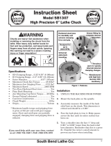
Figure 1. Features.
Four chuck
alignment set
screws
Grease fitting for
complete internal
lubrication
Universal
plain-back
mounting
Hardened steel jaws
for durability and
extreme clamping
force and grip
Two-piece
jaws for speedy
internal/external
clamping changes
Designed for
up to
4000 RPM

6. Removethebackplatefromthelatheand
placeitonaworkbench.
7. Setthechuckonthebackplate,androughly
alignthechuckusingthealignmentset
screws.
8. Useatransferpunchtomarkthebackplate.
Ifatransferpunchisnotavailable,adrill
bitofthesamesizeasthemountingholesin
thechuckcanbeused.Lightlytaponthebit,
rotateit90°andtapitagain.
9. Centerpunchthemarks.Drillandtapthe
holesforM10-1.5threads.
10. Cleanandstoneallmatingsurfacesuntil
theyareperfectlycleanandnoburrsexist.
11. InstallthechuckandsnugtheM10-1.5cap
screwsinanalternatingpatternuntilyou
reachanaltorqueof53.5ft/lbs.Alternating
thetighteningprocessavoidschuckwarpage.
Ifyouareinstallingthechuckbythreading
theM10-1.5hexboltsintothechuckfrom
thebacksideofthemountingplate,repeat
Step 11onthesebolts,andtorquethebolts
to30 ft/lbs.
12. Usinga6mmhexwrench,lightlysnugall
fourchuckalignmentsetscrews.
13. Clampa1"diametertestblankintothe
chuck,installatestindicator.Rotatethe
chuckbyhandandmeasurethechuck
concentricity.
14. Basedonyourreadings,adjustthe
alignmentsetscrewstobringthechuck
intonalalignment.Thetypicalalignment
repeatabilityforthesamediameter
workpiecewhenswappingwillbe0.0005".
Formaximumaccuracy,clampyour
workpieceinthechuckandrealignby
tighteningorlooseningthesetscrews.If
allthesetscrewsaretight,correctionof
alignmentcanalsobedonebylooseningone
ormoresetscrews.
Note: Ifthechuckmustmove0.001"orlessto
bringtheworkpieceintoalignment,itisnot
necessarytoloosenthechuckmountingbolts
beforeusingtheadjustmentsetscrews.
Operation and Safety
• Chuck Key Safety:Achuckkeyleftinthe
chuckcanbecomeadangerousprojectile
whenthespindleisstarted.Alwaysremove
thechuckkeyafterusingit.Developahabit
ofnottakingyourhandoffofachuckkey
unlessitisawayfromthemachine.
•
Disconnect Power: Disconnectthelathe
frompowerbeforeinstallingandremoving
thechuckordoinganymaintenanceor
adjustments.Accidentallathestartupcan
causesevereinjuryordeath.
•
Secure Clamping: Athrownworkpiecemay
causesevereinjuryorevendeath.When
swappingthechuckjawpositions,usea
torquewrenchtore-torquetheM8-1.25
jawmountingcapscrewsto29ft/lbs.When
clampingaworkpiece,maximumgripping
forceisattainedatfulljawandscrollgear
engagement.Ifthejawandscrollgearare
partiallyengaged,clampingforceisreduced.
•
Chuck Speed Rating: Exceedingthe
maximumratedspeedindicatedonthe
chuck,orusingexcessivespindlespeeds
withanunbalancedworkpiece,cancause
theworkpiecetobethrownfromthechuck
causingasevereimpactinjuryorevendeath.
Alwaysusetheappropriatespindlespeedfor
thejob.
•
Large Chucks: Largechucksarevery
heavyanddifficulttograsp,whichcanlead
tocrushedfingersorhandsifmishandled.
Getassistancewheninstallingorremoving
largechuckstoreducethisrisk.Protectyour
handsandtheprecisiongroundwaysby
usingachuckcradleorpieceofplywoodover
thewaysofthelathewhenservicingchucks.
•
Safe Clearances: Oftenchuckjawswill
protrudepastthediameterofthechuckand
cancontactacoolantnozzle,tooling,tool
post,ornearbycomponents.Beforestarting
thespindle,makesuretheworkpieceand
thechuckjawshaveadequateclearanceby
rotatingthespindlethroughitsentirerange
ofmotionbyhand.
-2-
Mfg.Since3/10
ModelSB1314
INSTRUCTIONS

Care & Maintenance
Foroptimumperformancefromyourchuck,
followthemaintenanceschedulebelow,and
neverhammeronthechuck,jaws,oraworkpiece
clampedinthechuck.Neversubjectthechuckto
abrasives,ame,orwater.
Daily:
• Check/correctloosemountingbolts.
• Useavacuum,rag,orbrushtocleanthe
chuckafteruse.Neveruseairpressureto
cleanchipsawayfromachuck.
• Wipethechuckdownwithathincoatofway
oiltopreventsurfacerust.
• Greasethechuckttingwithonetotwo
pumpsofNLGI#2grease.
Ifthechuckeverbecomesstifftooperate,itmay
havebeencontaminatedwithmetalchipsor
abrasivesfromneglectorpoorservicepractices.
Thechuckmustbedissembled,cleaned,andre-
lubricated.
To disassemble the chuck for a full cleaning
and lubrication service:
1. DISCONNECTLATHEFROMPOWER!
2. Markthechuckandthemountingplate
wheretheymatetoensurethatwhen
reassembledbothhalveslineup.Next,
unboltthechuckandseparatebothhalves.
3. Insertandrotatethechuckkey
counterclockwiseuntilthescroll-gearhas
releasedallthreejawsfromthechuck.
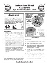
4. Usinga4mmand6mmhexwrench,a#1
standardscrewdriver,andaratchetwitha
7mmsocket,startat#1anddisassemblethe
chuckinthesequenceshowninFigure 2.
Always disconnect
machine from power before
performing maintenance or
serious personal injury may
result.
!
5. Usingmineralspirits,cleananddryall
components.Inspectallbores,teeth,pins,
andmatingsurfacesforwear,burrs,galling,
rust,orcracks.
6. Withoutchangingthedimensionofanypart,
useawirebrush,emerycloth,ordressing
stones,toremoveallrust,burrs,andany
highspotscausedbygalling.
7. CoatallpartswithanyautomotiveNLGI#2
grease,andcarefullyreassemblethechuck
inthereverseordershowninFigure 2.
8. Rotatethechuckkeyclockwiseuntilyou
seethetipofthescroll-gearleadthreadjust
begintoenterjawguide#1.
9. Insertjaw#1intojawguide#1,andholdthe
jawagainstthescroll-gear.
10. Rotatethechuckkeyclockwiseoneturnto
engagethetipofthescroll-gearleadthread
intothejaw.Pullthejaw;itshouldbelocked
intothejawguide.
11. Installtheotherjawsinthesamemanner,
andinstallanewgreasettingifballor
nippleleakgrease.
12. Lineupthetimingmarkonthechuckand
themountingplate,andfastenbothhalves
bytighteningandtorquingthefastenersas
outlinedinStep 11 in Installation.
2
3
6
4
5
1
Figure 2. Chuck sequence of disassembly.
7
Note: Each jaw is marked
1, 2, or 3 to correspond
to its marked slot in the
chuck
Mfg.Since3/10 ModelSB1314
-3-
INSTRUCTIONS

Copyright © March, 2010 By South Bend Lathe Co. Revised February, 2011 (CR)
WARNING: No portion of this manual may be reproduced in any shape or form
without the written approval of South Bend Lathe Co.
#CR12663 Printed in Taiwan.
www.southbendlathe.com
Troubleshooting
Ifyouneedreplacementparts,orifyouareunsurehowtodoanyofthesolutionsgivenhere,feelfree
tocallusat(360)734-1540.
Symptom Possible Cause Possible Solution
Thechuckhas
hardspotsorbinds
completely.
1.
Jawisinwrongposition.
1.
Reinstalljawsincorrectorderandpositiononscroll
gear.
2.
Lackoflubrication,rust,burrs,or
metalshavingsinsideofchuck.
2.
Disassemble,de-burr,clean,andlubricatechuck.
3.
Brokentoothonthepinionorthe
scrollgear.
3.
Disassemble,replacebrokenpartsifpossible,and
reassemblechuck.
Theworkpieceslips
inthejaws.
1.
Incorrectjaworworkpiececlamping
position.
1.
Repositionjawsandworkpieceformaximumscroll
gearandjawengagementisachieved.
2.
Insufcientpinionandscrollgear
torque.
2.
Tightenchuckkeyto65ft/lbs.
3.
Cuttingoverload.
3.
Reducecuttingdepthorfeedrate.
4.
Chuckisbindingbeforefull
clampingisachieved.
4.
Disassembleandservice/rebuildchuck.
Clampingaccuracy
ispoor.
1.
Workpieceisimproperlyclampedor
jawislooseorincorrectlyseated.
1.
Removejaws,clean,de-burr,andre-installwithjaw
mountingcapscrewstorquedto29ft/lbs.
2.
Chuckloose,mountingisoffcenter,
oritisimproperlyseated.
2.
Removechuck,cleanandde-burrmounting,andre-
install,ormachineanewmountingplate.
1
13
10
12
11
6
8
9
7
4
3
5
2
15
14
16
17
REF PART # DESCRIPTION
1 PSB1314001 GREASE FITTING
2 PSB1314002 TOP JAW
3 PCAP33M CAP SCREW M5-.8 X 12
4 PSB1314004 BACK COVER
5 PSB1314005 LOCK PIN
6 PSB1314006 PINION
7 PSB1314007 SCROLL GEAR
8 PSB1314008 CHUCK KEY W/SPRING
9 PSB1314009 COMPRESSION SPRING
10 PCAP171M CAP SCREW M10-1.5 X 80 BLK C12.9
11 PCAP172M CAP SCREW M8-1.25 X 20 BLK C12.9
12 PAW08M HEX WRENCH 8MM
13 PSB1314013 BOTTOM JAW SET OF 3
14 PSB1314014 CHUCK BODY
15 PB174M HEX BOLT M10-1.5 X 35 BLK C12.9
16 PSS108M SET SCREW M12-1.75 X 10
17 PSB1314017 FLANGE PIN
Parts Diagram Parts List
Please Note: We included this breakdown for service purposes only. Since many of the parts shown are machined to each
individual chuck, they are not available as replacement items.
-4-
Mfg.Since3/10
ModelSB1314
INSTRUCTIONS
/