Supermicro SuperServer 6027R-E1R12N User manual
- Category
- Server barebones
- Type
- User manual

®
SUPER STORAGE SYSTEM
6027R-E1R12N
SUPER
USER’S MANUAL
1.0

The information in this User’s Manual has been carefully reviewed and is believed to be accurate.
The vendor assumes no responsibility for any inaccuracies that may be contained in this document,
makes no commitment to update or to keep current the information in this manual, or to notify any
person or organization of the updates. Please Note: For the most up-to-date version of this
manual, please see our web site at www.supermicro.com.
Super Micro Computer, Inc. ("Supermicro") reserves the right to make changes to the product
described in this manual at any time and without notice. This product, including software and docu-
mentation, is the property of Supermicro and/or its licensors, and is supplied only under a license.
Any use or reproduction of this product is not allowed, except as expressly permitted by the terms
of said license.
IN NO EVENT WILL SUPERMICRO BE LIABLE FOR DIRECT, INDIRECT, SPECIAL, INCIDENTAL,
SPECULATIVE OR CONSEQUENTIAL DAMAGES ARISING FROM THE USE OR INABILITY TO
USE THIS PRODUCT OR DOCUMENTATION, EVEN IF ADVISED OF THE POSSIBILITY OF
SUCH DAMAGES. IN PARTICULAR, SUPERMICRO SHALL NOT HAVE LIABILITY FOR ANY
HARDWARE, SOFTWARE, OR DATA STORED OR USED WITH THE PRODUCT, INCLUDING THE
COSTS OF REPAIRING, REPLACING, INTEGRATING, INSTALLING OR RECOVERING SUCH
HARDWARE, SOFTWARE, OR DATA.
Any disputes arising between manufacturer and customer shall be governed by the laws of Santa
Clara County in the State of California, USA. The State of California, County of Santa Clara shall
be the exclusive venue for the resolution of any such disputes. Super Micro's total liability for all
claims will not exceed the price paid for the hardware product.
FCC Statement: This equipment has been tested and found to comply with the limits for a Class A
digital device pursuant to Part 15 of the FCC Rules. These limits are designed to provide reasonable
protection against harmful interference when the equipment is operated in a commercial environ-
ment. This equipment generates, uses, and can radiate radio frequency energy and, if not installed
and used in accordance with the manufacturer’s instruction manual, may cause harmful interference
with radio communications. Operation of this equipment in a residential area is likely to cause harmful
interference, in which case you will be required to correct the interference at your own expense.
California Best Management Practices Regulations for Perchlorate Materials: This Perchlorate warn-
ing applies only to products containing CR (Manganese Dioxide) Lithium coin cells. “Perchlorate
Material-special handling may apply. See www.dtsc.ca.gov/hazardouswaste/perchlorate”
WARNING: Handling of lead solder materials used in this
product may expose you to lead, a chemical known to the
State of California to cause birth defects and other repro-
ductive harm.
Manual Revision 1.0
Release Date: March 20, 2012
Unless you request and receive written permission from Super Micro Computer, Inc., you may not
copy any part of this document.
Information in this document is subject to change without notice. Other products and companies
referred to herein are trademarks or registered trademarks of their respective companies or mark
holders.
Copyright © 2012 by Super Micro Computer, Inc.
All rights reserved.
Printed in the United States of America

iii
Preface
Preface
About This Manual
This manual is written for professional system integrators and PC technicians. It
provides information for the installation and use of the 6027R-E1R12N. Installation
and maintainance should be performed by experienced technicians only.
The 6027R-E1R12N is a high-end storage system based on the SC826E16-R920LP
2U rackmountable chassis and the X9DRi-LN4F+ dual processor serverboard.
Manual Organization
Chapter 1: Introduction
The fi rst chapter provides a checklist of the main components included with the
system and describes the main features of the X9DRi-LN4F+ serverboard and the
SC826E16-R920LP chassis.
Chapter 2: Server Installation
This chapter describes the steps necessary to install the 6027R-E1R12N into a
rack and check out the server confi guration prior to powering up the system. If your
server was ordered without processor and memory components, this chapter will
refer you to the appropriate sections of the manual for their installation.
Chapter 3: System Interface
Refer here for details on the system interface, which includes the functions and
information provided by the control panel on the chassis as well as other LEDs
located throughout the system.
Chapter 4: System Safety
You should thoroughly familiarize yourself with this chapter for a general overview
of safety precautions that should be followed when installing and servicing the
6027R-E1R12N.

SUPERSTORAGESYSTEM 6027R-E1R12N User's Manual
iv
Chapter 5: Advanced Serverboard Setup
Chapter 5 provides detailed information on the X9DRi-LN4F+ serverboard, includ-
ing the locations and functions of connections, headers and jumpers. Refer to this
chapter when adding or removing processors or main memory and when reconfi g-
uring the serverboard.
Chapter 6: Advanced Chassis Setup
Refer to Chapter 6 for detailed information on the SC826E16-R920LP chassis.
You should follow the procedures given in this chapter when installing, removing or
reconfi guring SATA or peripheral drives and when replacing system power supply
units and cooling fans.
Chapter 7: BIOS
The BIOS chapter includes an introduction to BIOS and provides detailed informa-
tion on running the CMOS Setup Utility.
Appendix A: BIOS Error Beep Codes
Appendix B: System Specifi cations

Notes
Preface
v

vi
Table of Contents
Chapter 1 Introduction
1-1 Overview .........................................................................................................1-1
1-2 Serverboard Features .....................................................................................1-2
Processors ......................................................................................................1-2
Memory ...........................................................................................................1-2
Serial ATA ........................................................................................................ 1-2
PCI Expansion Slots .......................................................................................1-2
Rear I/O Ports .................................................................................................1-2
1-3 Server Chassis Features ................................................................................1-3
System Power ................................................................................................. 1-3
Hard Drive Subsystem .................................................................................... 1-3
Front Control Panel .........................................................................................1-3
Cooling System ............................................................................................... 1-3
1-4 Contacting Supermicro ....................................................................................1-6
Chapter 2 Server Installation
2-1 Overview .........................................................................................................2-1
2-2 Unpacking the System .................................................................................... 2-1
2-3 Preparing for Setup .........................................................................................2-1
Choosing a Setup Location ............................................................................. 2-1
Rack Precautions ............................................................................................ 2-2
Server Precautions ..........................................................................................2-2
Rack Mounting Considerations .......................................................................2-3
Ambient Operating Temperature ................................................................ 2-3
Reduced Airfl ow .........................................................................................2-3
Mechanical Loading ................................................................................... 2-3
Circuit Overloading .....................................................................................2-3
Reliable Ground ......................................................................................... 2-3
2-4 Installing the System into a Rack ................................................................... 2-4
Separating the Sections of the Rack Rails .....................................................2-4
Installing the Inner Rail Extension ..................................................................2-4
Outer Rack Rails .............................................................................................2-6
Chapter 3 System Interface
3-1 Overview .........................................................................................................3-1
3-2 Control Panel Buttons ..................................................................................... 3-1
Reset ...............................................................................................................3-1
Power ..............................................................................................................3-1
SUPERSTORAGESYSTEM 6027R-E1R12N User's Manual

vii
3-3 Control Panel LEDs ........................................................................................ 3-2
Power Fail ....................................................................................................... 3-2
Overheat/Fan Fail: .......................................................................................... 3-2
NIC1 ................................................................................................................3-2
NIC2 ................................................................................................................3-2
HDD .................................................................................................................3-3
Power ..............................................................................................................3-3
3-4 Drive Carrier LEDs .......................................................................................... 3-3
Chapter 4 System Safety
4-1 Electrical Safety Precautions ..........................................................................4-1
4-2 General Safety Precautions ............................................................................ 4-2
4-3 ESD Precautions .............................................................................................4-3
4-4 Operating Precautions .................................................................................... 4-4
Chapter 5 Advanced Serverboard Setup
5-1 Handling the Serverboard ............................................................................... 5-1
Precautions .....................................................................................................5-1
Unpacking .......................................................................................................5-2
5-2 Connecting Cables ..........................................................................................5-2
Connecting Data Cables ................................................................................. 5-2
Connecting Power Cables ..............................................................................5-2
Connecting the Control Panel ......................................................................... 5-2
5-3 Rear I/O Ports .................................................................................................5-3
5-4 Installing the Processor and Heatsink ............................................................ 5-4
Installing an LGA2011 Processor ....................................................................5-4
Installing a Passive CPU Heatsink ................................................................. 5-7
Removing the Heatsink ................................................................................... 5-8
5-5 Installing Memory ............................................................................................5-9
Memory Support ..............................................................................................5-9
DIMM Installation ............................................................................................ 5-9
5-6 Adding PCI Add-On Cards ............................................................................ 5-12
5-7 Serverboard Details ...................................................................................... 5-13
X9DRi-LN4F+ Quick Reference .................................................................... 5-14
5-8 Connector Defi nitions ...................................................................................5-16
5-9 Jumper Settings ............................................................................................5-23
5-10 Onboard Indicators ........................................................................................5-27
5-11 SATA Ports ....................................................................................................5-28
5-12 Installing Software .........................................................................................5-29
SuperDoctor III ..............................................................................................5-30
Table of Contents

viii
Chapter 6 Advanced Chassis Setup
6-1 Static-Sensitive Devices ..................................................................................6-1
Precautions .....................................................................................................6-1
Unpacking .......................................................................................................6-1
6-2 Control Panel ..................................................................................................6-2
6-3 Accessing the Inside of the Chassis ............................................................... 6-2
6-4 System Fans ...................................................................................................6-3
System Fan Failure ......................................................................................... 6-3
Replacing System Fans .................................................................................. 6-4
6-5 Air Shroud .......................................................................................................6-5
6-6 Drive Bay Installation/Removal .......................................................................6-6
Accessing the Drive Bays ............................................................................... 6-6
SATA Drive Installation .................................................................................... 6-6
Hard Drive Backplane ..................................................................................... 6-8
6-7 Power Supply ..................................................................................................6-9
Power Supply Failure ......................................................................................6-9
Removing/Replacing the Power Supply .......................................................... 6-9
6-8 Attaching a JBOD Expansion Chassis ...........................................................6-11
Chapter 7 BIOS
7-1 Introduction ...................................................................................................... 7-1
Starting BIOS Setup Utility ..............................................................................7-1
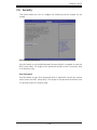
How To Change the Confi guration Data ......................................................... 7-1
Starting the Setup Utility .................................................................................7-2
7-2 Main Setup ......................................................................................................7-2
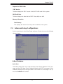
7-3 Advanced Setup Confi gurations......................................................................7-3
7-3 Event Logs .................................................................................................... 7-23
7-4 IPMI ............................................................................................................... 7-26
7-5 Boot ............................................................................................................... 7-28
7-6 Security ......................................................................................................... 7-29
7-7 Save & Exit ................................................................................................... 7-30
Appendix A BIOS Error Beep Codes
Appendix B System Specifi cations
SUPERSTORAGESYSTEM 6027R-E1R12N User's Manual

Chapter 1
Introduction
1-1 Overview
The 6027R-E1R12N is a high-end storage system comprised of two main subsys-
tems: the SC826E16-R920LP 2U/rack mount chassis and the X9DRi-LN4F+ dual
processor serverboard. Please refer to our web site for information on operating
systems that have been certifi ed for use with the system (www.supermicro.com).
In addition to the serverboard and chassis, various hardware components have
been included with the 6027R-E1R12N, as listed below:
• Two passive CPU heatsinks (SNK-P0048P)
• Three 8-cm system fans (FAN-0126L4)
• One air shroud (MCP-310-29001-0N)
• SATA Accessories
One SATA backplane (BPN-SAS2-826EL1)
Twelve drive carriers (MCP-220-00075-OB)
• Hardware RAID Controller ( AOC-SAS2LP-Hi8R)
• JBOD Expansion Port (CBL-035L-LP)
• One rackmount kit (MCP-290-00053-0N)
• One CD containing drivers and utilities
• 6027R-E1R12N User's Manual
Chapter 1: Introduction
1-1

1-2
SUPERSTORAGESYSTEM 6027R-E1R12N User's Manual
1-2 Serverboard Features
The 6027R-E1R12N is built around the X9DRi-LN4F+, a dual processor serverboard
based on the Intel C600 chipset and designed to provide maximum performance.
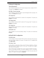
Below are the main features of the X9DRi-LN4F+. (See Figure 1-1 for a block
diagram of the chipset).
Processors
The X9DRi-LN4F+ supports single or dual Intel® Xeon E5-2600 Series processors.
Please refer to the serverboard description pages on our web site for a complete
listing of supported processors (www.supermicro.com).
Memory
The X9DRi-LN4F+ has 24 DIMM slots that can support up to 768 GB of ECC reg-
istered DDR3-1333/1066/800 SDRAM. Both 1.5V and 1.35V DIMMs are supported.
See Chapter 5 for details.
Serial ATA
A SATA controller is also integrated into the chipset to provide two SATA 3 (6/Gbps)
and four SATA 2 (3 Gbps) ports, which are RAID 0, 1, 5 and 10 supported. The
SATA drives are hot-swappable units. RAID 5 supported with Windows OS only).
Note: The operating system you use must have RAID support to enable the hot-
swap capability and RAID function of the SATA drives.
PCI Expansion Slots
The X9DRi-LN4F+ has four PCI-E 3.0 x16 slots, one PCI-E 3.0 x8 slot and one
PCI-E 3.0 x4 (in a x8) slot. The default confi guration includes an add-on card (AOC)
populating Slot #1 (PCI-E 3.0 x 16 slot) and a port plate with a JBOD expansion
port occupying slot #2 (PCI-E 3.0 x4).
Rear I/O Ports
The color-coded I/O ports include one COM port, a VGA port, four USB 2.0 ports
(additional USB headers are included on the serverboard), four gigabit Ethernet
ports and one external MiniSAS JBOD expansion port. A dedicated IPMI LAN port
is also included.

1-3
Chapter 1: Introduction
1-3 Server Chassis Features
The SC826E16-R920LP is an 2U form factor chassis designed to be used in a
storage confi guration. The following is a general outline of the main features of the
SC826E16-R920LP chassis.
System Power
The SC826E16-R920LP features a redundant 920W power supply composed of two
separate power modules. This power redundancy feature allows you to replace a
failed power supply without shutting down the system.
Hard Drive Subsystem
The SC826E16-R920LP chassis was designed to support 12 hot-swap SATA
hard drives.
Front Control Panel
The control panel on the SC826E16-R920LP provides you with system monitoring
and control. LEDs indicate system power, HDD activity, network activity, system
overheat and power supply failure. A main power button and a system reset button
are also included.
Cooling System
The SC826E16-R920LP chassis includes three 8-cm hot-plug system cooling fans
located in the middle section of the chassis. An air shroud channels the airfl ow from
the system fans to effi ciently cool the processor area of the system. Each power
supply module also includes a cooling fan.

1-4
SUPERSTORAGESYSTEM 6027R-E1R12N User's Manual
Figure 1-1. Intel C600 Chipset:
System Block Diagram
Note: This is a general block diagram. Please see Chapter 5 for details.
PROCESSOR
PROCESSOR
QPI
#1
DDR3 DIMM
#2
DDR3 DIMM
DDR3 DIMM
#3
DDR3 DIMM
DDR3 DIMM
#3
#2
#1
DDR3 DIMM
G
A
SSB
Intel C606/C602
PEG0
DMI
PEG1 [4:1]
USB
LPC
LAN
RJ45 RJ45
#1
SATA
SYSTEM
BIOS
CPU REAR
CPU FRONT
PEG1_8
PCI-E x16 Slot
USB
REAR
HDR 2X5
0,1
TPM HDR
TYPE-A
REAR
2,3
QPI
DDR3 DIMM
B
DDR3 DIMM
D
C
H
F
E
Socket 1
Socket 2
#1
#2
#3
#1
#2
#3
#1
#2
#3
#1
#2
#3
#1
#2
#3
#1
#2
#3
P0
P0
P1
P1
PE3 PE2 PE1 DMI
DMI
#2
PCI-E x8 Slot
PCI-E x16 Slot
#3
x4
x16
x16
x4
HDR 2X5
BMC VGA
VGA CONN
DDR III
PHY1
LAN
RTL8211
SPI
x1
RJ45 RJ45
#6
PCI-E x16 Slot
#5
PCI-E x16 Slot
#4
PCI-E x16 Slot
x16
x4
x4
[7.4]
[3.0]
SIO
W83527
A
B
C
A
B
C
A
B
C
A
B
C
A
B
C
A
B
C
A
B
C
A
B
C
4,5
6, 7
PE3
PE2
PE1
9
SATA
SCU
#1~#6
#1~#8
(For X9DR3
-LN4F+ Only)
(4 SATA2 for X9DRi
-LN4F+ Only)

1-5
Chapter 1: Introduction
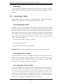
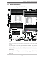
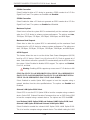
Figure 1-2. X9DRi-LN4F+ Serverboard
JRK1
JF1
JPI2C1
JPW3
JPW2
JPW1
JSD1
SP1
J18
J17
JBAT1
JP6
JP7
JI2C2
JI2C1
JL1
JOH1
FANB
FANA
FAN4
FAN3
FAN2
FAN6
FAN1
SW1
JPP1
JPP0
J21
JBT1
LEM1
JWP1
JPG1
JWD1
JPL1
JPME2
JPME1
USB4/5
JTPM1
XDP-PCH
(in X8 Slot)
CPU2 Slot6 PCI-E 3.0x8
CPU2 Slot5 PCI-E 3.0 x16
CPU2 Slot4 PCI-E 3.0 x16
CPU1 Slot3 PCI-E 3.0 x16
CPU1 Slot2 PCI-E 3.0 x4
BIOS BOX
CPU1 Slot1 PCI-E 3.0 x16
SAS0~3
SAS4~7
I-SATA0
I-SATA1
P2 DIMMF3
P2 DIMMF1
P2 DIMMF2
P2 DIMME3
P2 DIMME2
P2 DIMME1
P2 DIMMG1
P2 DIMMH1
P2 DIMMG3
P2 DIMMG2
P2 DIMMH2
P2 DIMMH3
COM1
USB6/7
UID
IPMI_LAN
Alaways populate DIMMx1 first
P1 DIMMA2
P1 DIMMA1
P1 DIMMB3
P1 DIMMB2
P1 DIMMB1
P1 DIMMA3
P1 DIMMC1
P1 DIMMC2
P1 DIMMC3
P1 DIMMD1
P1 DIMMD2
P1 DIMMD3
CPU2
I-SATA5
I-SATA4
I-SATA3
I-SATA2
LAN2/4
VGA
XDP-CPU
CPU1
COM2
BMC
CTRL
LAN1/3
USB 0/1
KB/Mouse
JBR1
PHY
FAN5
BIOS
LAN
CTRL
PCH
LE1
X9DR6-LN4F+/X9DRi-LN4F+
Rev. 1.10
Alaways populate DIMMx1 first
USB9
SAS
CTRL
USB 2/3
JSTBY1
IPMB
1
1
JD1
JF2
LE2
JPB1
JBMC1
JBOD ExpansionPort/Cable
AOC-SAS2LP-H8iR
Note: The SSG-6027R-E1R12N comes pre-installed with a Hardware RAID con-
troller installed in PCI-E slot 1 and a JBOD expansion port installed in PCI-E slot
2. Serverboard SAS components shown in the fi gure above are not included on
the X9DRi-LN4F+

1-6
SUPERSTORAGESYSTEM 6027R-E1R12N User's Manual
1-4 Contacting Supermicro
Headquarters
Address: Super Micro Computer, Inc.
980 Rock Ave.
San Jose, CA 95131 U.S.A.
Tel: +1 (408) 503-8000
Fax: +1 (408) 503-8008
Email: [email protected] (General Information)
[email protected] (Technical Support)
Web Site: www.supermicro.com
Europe
Address: Super Micro Computer B.V.
Het Sterrenbeeld 28, 5215 ML
's-Hertogenbosch, The Netherlands
Tel: +31 (0) 73-6400390
Fax: +31 (0) 73-6416525
Email: [email protected] (General Information)
[email protected] (Technical Support)
[email protected] (Customer Support)
Asia-Pacifi c
Address: Super Micro Computer, Inc.
4F, No. 232-1, Liancheng Rd.
Chung-Ho 235, Taipei County
Taiwan, R.O.C.
Tel: +886-(2) 8226-3990
Fax: +886-(2) 8226-3991
Web Site: www.supermicro.com.tw
Technical Support:
Email: [email protected]
Tel: 886-2-8226-5990

Chapter 2: Server Installation
2-1
Chapter 2
Server Installation
2-1 Overview
This chapter provides a quick setup checklist to get your 6027R-E1R12N up and
running. Following these steps in the order given should enable you to have the
system operational within a minimum amount of time. This quick setup assumes
that your system has come to you with the processors and memory preinstalled. If
your system is not already fully integrated with a serverboard, processors, system
memory etc., please turn to the chapter or section noted in each step for details on
installing specifi c components.
2-2 Unpacking the System
You should inspect the box the 6027R-E1R12N was shipped in and note if it was
damaged in any way. If the server itself shows damage you should fi le a damage
claim with the carrier who delivered it.
Decide on a suitable location for the rack unit that will hold the 6027R-E1R12N.
It should be situated in a clean, dust-free area that is well ventilated. Avoid areas
where heat, electrical noise and electromagnetic fi elds are generated. You will also
need it placed near a grounded power outlet. Read the Rack and Server Precau-
tions in the next section.
2-3 Preparing for Setup
The box the 6027R-E1R12N was shipped in should include two sets of rail assem-
blies, two rail mounting brackets and the mounting screws you will need to install the
system into the rack. Follow the steps in the order given to complete the installation
process in a minimum amount of time. Please read this section in its entirety before
you begin the installation procedure outlined in the sections that follow.
Choosing a Setup Location
• Leave enough clearance in front of the rack to enable you to open the front door
completely (~25 inches) and approximately 30 inches of clearance in the back
of the rack to allow for suffi cient airfl ow and ease in servicing.

2-2
SUPERSTORAGESYSTEM 6027R-E1R12N User's Manual
• This product is for installation only in a Restricted Access Location (dedicated
equipment rooms, service closets and the like).
• This product is not suitable for use with visual display work place devices
acccording to §2 of the the German Ordinance for Work with Visual Display
Units.
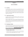
!
!
Warnings and Precautions!
Rack Precautions
• Ensure that the leveling jacks on the bottom of the rack are fully extended to
the fl oor with the full weight of the rack resting on them.
• In single rack installation, stabilizers should be attached to the rack. In multiple
rack installations, the racks should be coupled together.
• Always make sure the rack is stable before extending a component from the
rack.
• You should extend only one component at a time - extending two or more si-
multaneously may cause the rack to become unstable.
Server Precautions
• Review the electrical and general safety precautions in Chapter 4.
• Determine the placement of each component in the rack before you install the
rails.
• Install the heaviest server components on the bottom of the rack fi rst, and then
work up.
• Use a regulating uninterruptible power supply (UPS) to protect the server from
power surges, voltage spikes and to keep your system operating in case of a
power failure.
• Allow any hot plug drives and power supply modules to cool before touching
them.
• Always keep the rack's front door and all panels and components on the servers
closed when not servicing to maintain proper cooling.

Chapter 2: Server Installation
2-3
Rack Mounting Considerations
Ambient Operating Temperature
If installed in a closed or multi-unit rack assembly, the ambient operating tempera-
ture of the rack environment may be greater than the ambient temperature of the
room. Therefore, consideration should be given to installing the equipment in an
environment compatible with the manufacturer’s maximum rated ambient tempera-
ture (Tmra).
Reduced Airfl ow
Equipment should be mounted into a rack so that the amount of airfl ow required
for safe operation is not compromised.
Mechanical Loading
Equipment should be mounted into a rack so that a hazardous condition does not
arise due to uneven mechanical loading.
Circuit Overloading
Consideration should be given to the connection of the equipment to the power
supply circuitry and the effect that any possible overloading of circuits might have
on overcurrent protection and power supply wiring. Appropriate consideration of
equipment nameplate ratings should be used when addressing this concern.
Reliable Ground
A reliable ground must be maintained at all times. To ensure this, the rack itself
should be grounded. Particular attention should be given to power supply connec-
tions other than the direct connections to the branch circuit (i.e. the use of power
strips, etc.).

2-4
SUPERSTORAGESYSTEM 6027R-E1R12N User's Manual
2-4 Installing the System into a Rack
This section provides information on installing the SC826 chassis into a rack unit
with the quick-release rails provided. There are a variety of rack units on the market,
which may mean the assembly procedure will differ slightly. You should also refer to
the installation instructions that came with the rack unit you are using.
Separating the Sections of the Rack Rails
The chassis package includes two rail assemblies in the rack mounting kit. Each
assembly consists of two sections: an inner fi xed chassis rail that secures directly
to the server chassis and an outer fi xed rack rail that secures directly to the rack
itself.
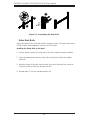
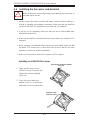
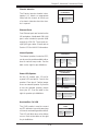
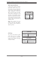
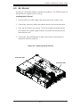
Installing the Inner Rail Extension
The SC826 chassis includes a set of inner rails in two sections: inner rails and inner
rail extensions. The inner rails are pre-attached to the chassis, and do not interfere
with normal use of the chassis if you decide not to use a server rack. The inner rail
extension is attached to the inner rail to mount the chassis in the rack.
Installing the Inner Rails
1. Place the inner rail extensions on the side of the chassis aligning the hooks
of the chassis with the rail extension holes. Make sure the extension faces
"outward" just like the pre-attached inner rail.
2. Slide the extension toward the front of the chassis.
3. Secure the chassis with 2 screws as illustrated. Repeat steps for the other
inner rail extension.

Chapter 2: Server Installation
2-5
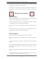
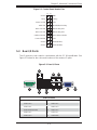
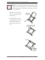
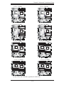
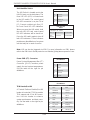
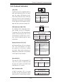
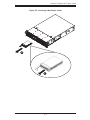
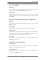
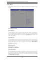
Figure 2-1: Separating the Rack Rails
1
1
1
2
1
4
1
3
Separating the Inner and Outer Rails
1. Locate the rail assembly in the chassis
packaging.
2. Extend the rail assembly by pulling it
outward.
3. Press the quick-release tab.
4. Separate the inner rail extension from
the outer rail assembly.
Rail Assembly
Extending the Rails
Quick-
Release Tab
Separating
the Inner Rail
Extension

2-6
SUPERSTORAGESYSTEM 6027R-E1R12N User's Manual
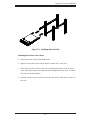
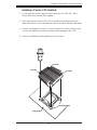
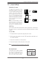
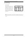
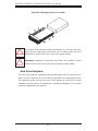
Outer Rack Rails
Outer rails attach to the rack and hold the chassis in place. The outer rails for the
SC826 chassis extend between 30 inches and 33 inches.
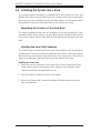
Installing the Outer Rails to the Rack
1. Secure the back end of the outer rail to the rack, using the screws provided.
2. Press the button where the two outer rails are joined to retract the smaller
outer rail.
3. Hang the hooks of the rails onto the rack holes and if desired, use screws to
secure the front of the outer rail onto the rack.
4. Repeat steps 1-3 for the remaining outer rail.
Figure 2-2. Assembling the Outer Rails
1
1
1
2
1
3
Page is loading ...
Page is loading ...
Page is loading ...
Page is loading ...
Page is loading ...
Page is loading ...
Page is loading ...
Page is loading ...
Page is loading ...
Page is loading ...
Page is loading ...
Page is loading ...
Page is loading ...
Page is loading ...
Page is loading ...
Page is loading ...
Page is loading ...
Page is loading ...
Page is loading ...
Page is loading ...
Page is loading ...
Page is loading ...
Page is loading ...
Page is loading ...
Page is loading ...
Page is loading ...
Page is loading ...
Page is loading ...
Page is loading ...
Page is loading ...
Page is loading ...
Page is loading ...
Page is loading ...
Page is loading ...
Page is loading ...
Page is loading ...
Page is loading ...
Page is loading ...
Page is loading ...
Page is loading ...
Page is loading ...
Page is loading ...
Page is loading ...
Page is loading ...
Page is loading ...
Page is loading ...
Page is loading ...
Page is loading ...
Page is loading ...
Page is loading ...
Page is loading ...
Page is loading ...
Page is loading ...
Page is loading ...
Page is loading ...
Page is loading ...
Page is loading ...
Page is loading ...
Page is loading ...
Page is loading ...
Page is loading ...
Page is loading ...
Page is loading ...
Page is loading ...
Page is loading ...
Page is loading ...
Page is loading ...
Page is loading ...
Page is loading ...
Page is loading ...
Page is loading ...
Page is loading ...
Page is loading ...
Page is loading ...
Page is loading ...
Page is loading ...
Page is loading ...
Page is loading ...
Page is loading ...
Page is loading ...
Page is loading ...
Page is loading ...
Page is loading ...
Page is loading ...
Page is loading ...
Page is loading ...
Page is loading ...
Page is loading ...
Page is loading ...
Page is loading ...
Page is loading ...
Page is loading ...
-
 1
1
-
 2
2
-
 3
3
-
 4
4
-
 5
5
-
 6
6
-
 7
7
-
 8
8
-
 9
9
-
 10
10
-
 11
11
-
 12
12
-
 13
13
-
 14
14
-
 15
15
-
 16
16
-
 17
17
-
 18
18
-
 19
19
-
 20
20
-
 21
21
-
 22
22
-
 23
23
-
 24
24
-
 25
25
-
 26
26
-
 27
27
-
 28
28
-
 29
29
-
 30
30
-
 31
31
-
 32
32
-
 33
33
-
 34
34
-
 35
35
-
 36
36
-
 37
37
-
 38
38
-
 39
39
-
 40
40
-
 41
41
-
 42
42
-
 43
43
-
 44
44
-
 45
45
-
 46
46
-
 47
47
-
 48
48
-
 49
49
-
 50
50
-
 51
51
-
 52
52
-
 53
53
-
 54
54
-
 55
55
-
 56
56
-
 57
57
-
 58
58
-
 59
59
-
 60
60
-
 61
61
-
 62
62
-
 63
63
-
 64
64
-
 65
65
-
 66
66
-
 67
67
-
 68
68
-
 69
69
-
 70
70
-
 71
71
-
 72
72
-
 73
73
-
 74
74
-
 75
75
-
 76
76
-
 77
77
-
 78
78
-
 79
79
-
 80
80
-
 81
81
-
 82
82
-
 83
83
-
 84
84
-
 85
85
-
 86
86
-
 87
87
-
 88
88
-
 89
89
-
 90
90
-
 91
91
-
 92
92
-
 93
93
-
 94
94
-
 95
95
-
 96
96
-
 97
97
-
 98
98
-
 99
99
-
 100
100
-
 101
101
-
 102
102
-
 103
103
-
 104
104
-
 105
105
-
 106
106
-
 107
107
-
 108
108
-
 109
109
-
 110
110
-
 111
111
-
 112
112


Supermicro SuperServer 6027R-E1R12N User manual
- Category
- Server barebones
- Type
- User manual
Ask a question and I''ll find the answer in the document
Finding information in a document is now easier with AI
Related papers
-
Supermicro SC946LE1C-R1K66JBOD User manual
-
-
Supermicro X9DRE-TF+ User manual
-
Supermicro X9DRE-LN4F User manual
-
-
Supermicro X9DRi-F Retail User manual
-
-
-
-
Other documents
-
Approx APPHDD08P Datasheet
-
-
 Supercmicro SC826 series User manual
-
 Sugon I620-G20 User manual
-
Omega DP80-SCAN Owner's manual
-
VIA Technologies VDLM-100-B User manual
-
 Supero H8DGU-LN4F+ User manual
-
Bull Bullx R423-E3 Installation guide
-
 Supero 5028R-E1CR12L User manual
-
ATEN IP9001 User manual


