StarTech.com ST12MHDLAN User manual

Category
AV receivers
Type
User manual

StarTech.com ST12MHDLAN is an HDMI® Over IP Extender Kit that allows you to extend an HDMI® audio and video signal over a Gigabit LAN network or point-to-point with no network hub. It supports 1080p video resolutions, digital stereo audio, and features built-in EDID monitor emulation for convenient plug-and-play installation. With a range of up to 330 feet (100 meters) over Cat5e/Cat6 Ethernet cable, it's ideal for high-definition applications like extending cable or satellite TV to multiple displays in your home or office.

StarTech.com ST12MHDLAN is an HDMI® Over IP Extender Kit that allows you to extend an HDMI® audio and video signal over a Gigabit LAN network or point-to-point with no network hub. It supports 1080p video resolutions, digital stereo audio, and features built-in EDID monitor emulation for convenient plug-and-play installation. With a range of up to 330 feet (100 meters) over Cat5e/Cat6 Ethernet cable, it's ideal for high-definition applications like extending cable or satellite TV to multiple displays in your home or office.

Manual Revision: 03/15/2013
For the most up-to-date information, please visit: www.startech.com
DE: Bedienungsanleitung - de.startech.com
FR: Guide de l'utilisateur - fr.startech.com
ES: Guía del usuario - es.startech.com
IT: Guida per l'uso - it.startech.com
NL: Gebruiksaanwijzing - nl.startech.com
PT: Guia do usuário - pt.startech.com
ST12MHDLAN
HDMI® Audio/Video Over IP Extender Kit
*actual product may vary from photos
Instruction Manual
FCC Compliance Statement
This equipment has been tested and found to comply with the limits for a Class B digital
device, pursuant to part 15 of the FCC Rules. These limits are designed to provide reasonable
protection against harmful interference in a residential installation. This equipment generates,
uses and can radiate radio frequency energy and, if not installed and used in accordance with
the instructions, may cause harmful interference to radio communications. However, there
is no guarantee that interference will not occur in a particular installation. If this equipment
does cause harmful interference to radio or television reception, which can be determined by
turning the equipment o and on, the user is encouraged to try to correct the interference by
one or more of the following measures:
Reorient or relocate the receiving antenna.
Increase the separation between the equipment and receiver.
Connect the equipment into an outlet on a circuit dierent from that to which the receiver
is connected.
Consult the dealer or an experienced radio/TV technician for help.
Use of Trademarks, Registered Trademarks, and other Protected Names and Symbols
This manual may make reference to trademarks, registered trademarks, and other
protected names and/or symbols of third-party companies not related in any way to
StarTech.com. Where they occur these references are for illustrative purposes only and do not
represent an endorsement of a product or service by StarTech.com, or an endorsement of the
product(s) to which this manual applies by the third-party company in question. Regardless
of any direct acknowledgement elsewhere in the body of this document, StarTech.com hereby
acknowledges that all trademarks, registered trademarks, service marks, and other protected
names and/or symbols contained in this manual and related documents are the property of
their respective holders.
Instruction Manual
i
Table of Contents
Introduction ............................................................................................1
Packaging Contents .................................................................................................................................1
System Requirements .............................................................................................................................. 1
Preparing Your Site ...................................................................................................................................3
Hardware Installation Using Gigabit LAN Network ...................................................................... 4
Hardware Reset Procedure .................................................................................................................... 6
EDID Copy .................................................................................................................................................... 6
Factory Default Setting ...........................................................................................................................6
Specications ..........................................................................................7
Technical Support ..................................................................................8
Warranty Information ............................................................................8
Instruction Manual
1
Introduction
The ST12MHDLAN HDMI® Over IP Extender kit lets you extend an HDMI® audio and
video signal over a Gigabit LAN network. The kit includes both the extender and
receiver for a complete all-in-one solution, and oers a highly scalable installation
when used with additional ST12MHDLANRX receiver units (sold separately). The
ST12MHDLANRX receivers can be connected to the same network to output the HDMI®
signal to over 100 additional displays.
This exible HDMI® extender can be connected through a Gigabit LAN portal and span
the entire distance of your network, or connected point-to-point with no network
hub for a small scale one-to-one extension of up to 330 feet (100 meters). Plus,
because the HDMI® signal is extended over standard Cat5e/Cat6 Ethernet cable with
RJ45 connectors, proprietary cables aren’t necessary, eliminating both the expense
and hassle of running specialized cables. For added versatility, up to 16 dierent
ST12MHDLAN Transmitter units can be added to a single network (IGMP Network
support required).
The HDMI® over IP Extender kit includes optional mounting hardware for a professional
and tidy installation.
Ideal for High-Denition applications, the extender supports 1080p video resolutions,
digital stereo audio, and features built-in EDID monitor emulation, which ensures
native resolution and maximum compatibility with your display or projector, for a
convenient plug-and-play installation.
Backed by a StarTech.com 2-year warranty and free lifetime technical support.
Packaging Contents
1 x HDMI® over IP Transmitter Unit
1 x HDMI® over IP Receiver Unit
2 x Mounting Bracket Kit
2 x Foot Pad Set
2 x Power Adapters
1 x Instruction Manual
System Requirements
HDMI® enabled video source (i.e. computer, Blu-ray Player)
HDMI® enabled display device(s) One for each Receiver (i.e. television, projector)
Available AC electrical outlet for the Transmitter, and each Receiver
HDMI® cable for each display
Gigabit Networking devices and cabling
Instruction Manual
2
Transmitter Unit
Receiver Unit
1. F2 (Not Active)
2. F1 (Used during factory
default setting)
3. Dip Rotary Switch (Used to
pair Transmitter to Receiver)
1. F2 (Used during EDID Copy
procedure)
2. F1 (Used during factory
default setting)
3. Dip Rotary Switch (Used to
pair Transmitter to Receiver)
1. Power Jack
2. Network Status LED
3. Reset Button
4. LAN Port (RJ-45 Connector)
5. Video In
6. Link OK POWER LED
1. Power Jack
2. Network Status LED
3. Reset Button
4. LAN Port (RJ-45 Connector)
5. Video Out
6. Link OK POWER LED
NOTE: Serial 1 (Control) Ports, and Serial 2 (AUX/EXT) Ports are not active
(Additional Receiver units sold seperately ST12MHDLANRX)
1
1
1
1
3
3
4
4
5
5
2
2
6
6
2
2
3
3
Instruction Manual
3
Preparing Your Site
NOTE: The ST12MHDLAN HDMI® extender kit can use a Gigabit LAN Network to
extend the signal. Most Gigabit Network portals have a cable length restriction of
330 ft. (100m). Refer to the manufacturer of the equipment to determine the length
restriction and ensure the Transmitter Unit, and Receiver Unit(s) are all within the
restricted range of the nearest network portal.
Ensure the Transmitter Unit, and Receiver Unit(s) are all situated near an available AC
electrical outlet.
1. Determine where the local video source (i.e. computer, Blu-ray Player) will be
located and set up the device.
2. Determine where the remote display will be located and place/ mount the
display appropriately.
3. (Optional) If using additional receiver units (ST12MHDLANRX sold separately),
determine where the remote displays will be located in and place/ mount the
displays appropriately.
Instruction Manual
4
Hardware Installation Using Gigabit LAN Network
1. Install Transmitter Unit
a) Position the Transmitter Unit near the video source (i.e. Computer, Blu-ray Player).
b) Connect an HDMI cable from the video source device (i.e. computer, Blu-ray
Player) to the Video In” port on the Transmitter Unit.
c) Connect the provided Transmitter Unit power supply.
2. Install Receiver Unit(s)
a) Position the Receiver Unit(s) near the video display (i.e. television, projector).
b) Connect an HDMI cable from the display Input to the “Video Out” port on the
Receiver Unit.
c) Connect the provided Receiver Unit power supply.
d) (optional) If using additional ST12MHDLANRX Receivers (sold separately), repeat
steps for each additional Receiver.
NOTE: The “Dip Rotary Switch on the Extender and each Receiver connected to the
network must be set in the same position for the devices to communicate.
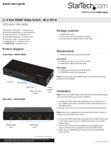
3. Connect the devices to a Gigabit LAN Network
a) Connect an RJ-45 terminated Cat5e/6 Ethernet cable to the “LAN Port (RJ-45
Connector) on the Transmitter unit, and all receiver units.
NOTE: If you are using surface cabling, ensure you have enough Category 5e/6
unshielded twisted pair (UTP) network cabling to connect the Transmitter Unit to the
Gigabit LAN hub, router, or switch.
OR
If you are using premises cabling, ensure that the Category 5e/6 unshielded twisted
pair (UTP) network cabling between the Transmitter and Gigabit LAN hub, router, or
switch has been properly terminated in a wall outlet in each location and there is a
patch cable long enough to connect the Network portal and Transmitter Unit to their
respective outlets.
b) Connect the other end of the Cat5e/6 cable run to a Gigabit LAN hub, router
or switch.
c) (optional) When adding additional Receiver Units (ST12MHDLANRX – Sold
separately), a run of Cat 5e/6 cable will be required from each device to the Gigabit
LAN hub, router or switch.
4. Your source video image will now appear on the Receiver unit(s) attached
video display.
Instruction Manual
5
(Optional) Point to Point Hardware Installation without Gigabit LAN Network
NOTE: While range is reduced to a maximum of 330 feet (100 Meters) the
ST12MHDLAN HDMI® extender kit also allows for extending the signal without a
Gigabit LAN Network by connecting the Transmitter directly to the Receiver using
CAT5e/6 cabling. This also eliminates the ability to add additional Receivers.
1. Install Transmitter Unit
d) Position the Transmitter Unit near the video source (i.e. Computer, Blu-ray Player).
e) Connect an HDMI® cable from the video source device (i.e. computer, Blu-ray
Player) to the “HDMI IN” on the Transmitter Unit.
f) Connect the provided Transmitter Unit power supply.
2. Install Receiver Unit(s)
e) Position the Receiver Unit(s) near the video display (i.e. television, projector).
f) Connect an HDMI® cable from the display Input to the Video Out” port on the
Receiver Unit.
g) Connect the provided Receiver Unit power supply.
NOTE: The “Dip Rotary Switch on the Extender and Receiver connected must be set in
the same position for the devices to communicate.
3. Install RJ-45 terminated Cat5e/6 Ethernet Cable
d) Connect an RJ-45 terminated Cat5e/6 Ethernet cable to the HDMI® Out Link
(RJ-45 Connector) on the Transmitter unit.
NOTE:
If you are using surface cabling, ensure you have enough Category 5e/6 unshielded
twisted pair (UTP) network cabling to connect the Transmitter Unit to the Receiver
Unit’s location, and that each end is terminated with a RJ45 connector.
OR
If you are using premises cabling, ensure that the Category 5e/6 unshielded twisted
pair (UTP) network cabling between the Transmitter and Receiver Units have been
properly terminated in a wall outlet in each location and there is a patch cable long
enough to connect the Remote Unit and the Host Unit to their respective outlets.
e) Connect the other end of the Cat5/6 cable run to the RJ45 connector on the
remote Unit Receiver Unit.
4. Your source video image will now appear on the remote unit(s) attached
video display.
Instruction Manual
6
Hardware Reset Procedure
NOTE: If video signal does not appear on the display a hardware reset can be
performed on the Transmitter Unit, or individual Receiver Units.
1. Press the reset button on the device using a pin point tool, such as a ballpoint pen
or a bent paper clip.
EDID Copy
EDID allows the video source to output the most ideal signal to the video display. The
“EDID Copy” function on the ST12MHDLANRX ensures that EDID is still active through
the Ethernet extender.
NOTE: If you using multiple receivers the EDID can only be copied from one unit, the
signal customized for that display will be applied to all displays connected through
additional receivers.
1. Disconnect the power cable from the Receiver.
2. Hold down the F2 button
3. Reconnect the Power while holding down the F2 button
4. Release F2 button after the power has been reconnected for 12 seconds (the
Network Status LED ashes yellow), EDID is now active through the
Ethernet extender.
Factory Default Setting
1. Disconnect the power cable from the Transmitter/Receiver.
2. Hold down the F1 button
3. Reconnect the Power while holding down the F1 button
4. Release F1 button after the power has been reconnected for 17 seconds (the Link
OK POWER LED ashes green and blue)
5. Reconnect the Power again.
Instruction Manual
7
Specications
Maximum Digital Resolutions 1920x1200 @60Hz
Supported Resolutions 1920 x 1200 (1080p)
Wide Screen Supported Yes
Audio Specications Stereo Sound
Interface HDMI®
Cabling Cat 5e UTP or better
Audio Yes
Rack-Mountable Yes
Industry Standards
HDMI®
HDCP
Daisy-Chain Yes
Transmitter Connectors
1x HDMI® (19 pin)
1x RJ-45
Receiver Connectors
1x HDMI® (19 pin)
1x RJ-45
Power Adapter Input Voltage 100~240V
Power Adapter Input Current 0.4 A
Power Adapter Output Voltage 5 DC V
Power Adapter Output Current 2 A
Center Tip Polarity Positive
Plug Type M
Instruction Manual
8
Technical Support
StarTech.com’s lifetime technical support is an integral part of our commitment to
provide industry-leading solutions. If you ever need help with your product, visit
www.startech.com/support and access our comprehensive selection of online tools,
documentation, and downloads.
For the latest drivers/software, please visit www.startech.com/downloads
Warranty Information
This product is backed by a two year warranty.
In addition, StarTech.com warrants its products against defects in materials
and workmanship for the periods noted, following the initial date of purchase.
During this period, the products may be returned for repair, or replacement with
equivalent products at our discretion. The warranty covers parts and labor costs only.
StarTech.com does not warrant its products from defects or damages arising from
misuse, abuse, alteration, or normal wear and tear.
Limitation of Liability
In no event shall the liability of StarTech.com Ltd. and StarTech.com USA LLP (or their
ocers, directors, employees or agents) for any damages (whether direct or indirect,
special, punitive, incidental, consequential, or otherwise), loss of prots, loss of business,
or any pecuniary loss, arising out of or related to the use of the product exceed the
actual price paid for the product. Some states do not allow the exclusion or limitation
of incidental or consequential damages. If such laws apply, the limitations or exclusions
contained in this statement may not apply to you.
Hard-to-nd made easy. At StarTech.com, that isn’t a slogan. Its a promise.
StarTech.com is your one-stop source for every connectivity part you need. From
the latest technology to legacy products — and all the parts that bridge the old and
new — we can help you nd the parts that connect your solutions.
We make it easy to locate the parts, and we quickly deliver them wherever they need
to go. Just talk to one of our tech advisors or visit our website. You’ll be connected to
the products you need in no time.
Visit www.startech.com for complete information on all StarTech.com products and
to access exclusive resources and time-saving tools.
StarTech.com is an ISO 9001 Registered manufacturer of connectivity and technology
parts. StarTech.com was founded in 1985 and has operations in the United States,
Canada, the United Kingdom and Taiwan servicing a worldwide market.
  • Page 1 1
  • Page 2 2
  • Page 3 3
  • Page 4 4
  • Page 5 5
  • Page 6 6
  • Page 7 7
  • Page 8 8
  • Page 9 9
  • Page 10 10
  • Page 11 11
  • Page 12 12

StarTech.com ST12MHDLAN User manual

Category
AV receivers
Type
User manual

StarTech.com ST12MHDLAN is an HDMI® Over IP Extender Kit that allows you to extend an HDMI® audio and video signal over a Gigabit LAN network or point-to-point with no network hub. It supports 1080p video resolutions, digital stereo audio, and features built-in EDID monitor emulation for convenient plug-and-play installation. With a range of up to 330 feet (100 meters) over Cat5e/Cat6 Ethernet cable, it's ideal for high-definition applications like extending cable or satellite TV to multiple displays in your home or office.

Ask a question and I''ll find the answer in the document

Finding information in a document is now easier with AI