Page is loading ...

J-4) what to do should the rivet nut be abnormally deformed when pressing both
handles.
Slightly open both handles (1), rotate the tool the
align the head fixing holes and the long mandrel
seat fixing hole, then insert the fixing hole pin into
the holes and fasten with the pin retainer (2). The
threaded mandrel free rotation should cease.
Threaded
mandrel
Workpiece
A
bnormally
stuck rivet nu
t
Turn the whole
tool anti-
clockwise
Workpiece
Deformed stuck
rivet nu
t
Rotate the tool
Fixin
g
hole pin Pin retainer
Head fixin
g
holes
Workpiece
Deformed stuck
rivet nu
t
Turn the tool anti-clockwise to unscrew the
threaded mandrel from the stuck rivet nut (1).
Remove the pin retainer and the fixing hole pin. (2)
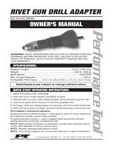
1742A
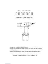
Operation Manual
Heavy duty & professional hand rivet nut with Quick-Drill Unit
This Illustrated Operation Manual includes the FEATURES, SPECIFICATIONS, PARTS LIST, OPERATION
INSTRUCTIONS, MAINTENANCE and TROUBLESHOOTING.
Before operating this tool, make sure you read this Illustrated OPERATION MANUAL carefully to ensure a
safe, correct and satisfactory use.
GB

A. FEATURES
- 1742A RIVET NUT TOOL is designed to fasten RIVET NUTS with THREADED MANDRELS, from M5 x 0.8
up to M10 x 1.5 or from 10-24/32 up to 3/8-16, in all materials (Aluminium, Steel and Stainless Steel/Inox)
and to firmly and securely forge Female Threads in thin base metals and pipes with weldless, tapping-free
and one-side work in order to fasten them to bolts.
- 1742A is equipped with a QUICK-DRILL UNIT, simply "Push & Pull" the DRILL UNIT KNOB to drive the
THREADED MANDREL or THREADED SOCKET to engage with and be released from the RIVET NUT or
RIVET BOLT/STUD quickly!
- 1742A is equipped with a FIXING-HOLE DEVICE, simply inserting the FIXING-HOLE PIN not only to
solve the problem of RIVET NUT stuck on the working THREADED MANDREL that might happen when
fastening RIVET NUT, but also to assist THREADED MANDREL to mount or dismount the TOOL easily just
with a single SERVICE WRENCH.
B. SPECIFICATIONS
1742A Tool Dimensions and Net Weight:
Dimensions (Closed type): L 530 x W 130 mm. Net Weight: 2.15 kgs.
- Working Capacity:
1) RIVET NUTS/THREADED INSERTS (Aluminium, Steel, Stainless Steel) ISO Metric Thread Size: M5x0.8,
M6x1.0, M8x1.25, M10x1.5 or UN Inch Thread Size: 10-24, 10-32, 1/4-20, 5/16-18, 3/8-16.
1742A Standard Accessories:
1) THREADED MANDRELS: ISO Metric Thread Size: M5x0.8, M6x1.0, M8x1.25, M10x1.5 : 1 pc of each.
or UN Inch Thread Size: 10-24, 10-32, 1/4-20, 5/16-18, 3/8-16 : 1 pc of each.
2) NOSEPIECES: ISO Metric Size: M5, M6, M8, M10 : 1 pc of each. or UN Inch Size: #10, 1/4, 5/16, 3/8 :
1 pc of each.
3) NOSEPIECE LOCK NUT, SERVICE WRENCH, SMALL RULE, FIXING-HOLE PIN, PIN RETAINER, PARTS
PLASTIC BOX, TRAY, STEEL CARRY CASE, OPERATION MANUAL: 1 pc of each.
16
J-3) What to do should a rivet nut be stuck on the threaded mandrel.
A
d
j
ust the stroke
adjuster
downwards
Protruding rivet
nut len
g
th L
Rivet nut
hei
g
ht
(
H
)
Rotate
nose
p
iece
Rear body
Stroke
indicator
Figure on the stroke
indicator=stroke distance
Press down both handles completely (1) till they
touch the rear body, and adjust the stroke adjuster
downwards so that its bottom is aligned to the
figure on the stroke indicator (2). The correct stroke
distance is set.
Having readjusted the stroke distance, the
protruding length (L) of the threaded mandrel
needs to be readjusted to the rivet nut height (H),
L=H, as per instructions in point “G”.
Head fixing
holes
Pull the drill unit knob downwards
then push it upwards to align the
head fixing holes and the long fixing
hole of the mandrel seat (1); fit the
fixing hole pin into the holes and
fasten it with the pin retainer (2).
The threaded mandrel free rotation
should cease.
Turn the tool anti-
clockwise
Fixing hole
p
in
Stuck rivet
nut
Threaded
mandrel
pliers
pliers
Stuck rivet
nu
t
head
Pin retainer
Drill unit knob
It is recommended two people do this job: while one holds
the rivet nut with pliers, the other turns the tool anti-
clockwise to unscrew the threaded mandrel from the rivet
nut (2). Remove the pin retainer and the fixing hole pin. (3)

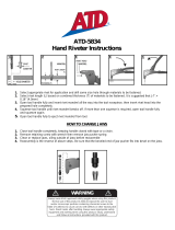
C. MAIN PARTS
NOSEPIECE
T
HREADED MANDREL
T
HREADED MANDREL
UPPER THREADS TO
ENGAGE RIVET NUT
THREADS
HEAD FIXING HOLES
HEAD
NOSEPIECE LOCK NUT
FIXING HOLE PIN
PIN RETAINER
MANDREL SEAT
MANDREL SEAT
FRONT BODY
LONG MANDREL SEAT
FIXING HOLE
J-2) How to readjust the correct stroke distance to protect the tool and the rivet nut
threads from damage, should you not manage to manually press the handles to touch
the rear body:
Gripped rivet nut &
work
p
iece
Stroke
indicator
Figure on stroke
indicator=stroke
distance
Rear body
handle handle
Gripped rivet nut &
work
p
iece
Threaded
mandrel
Drill unit
knob
Pull downwards,
without twisting
WARNING: do not insist in pressing
the handles.
Holding both handles, check and memorise
the figure on the stroke indicator.
Open both handles completely (1) and pull the drill
unit knob downwards, without twisting (2), to
unscrew the threaded mandrel from the gripped
rivet nut and Workpiece (3)

NOSEPIECE
T
HREADED MANDREL
HEAD
STROKE ADJUSTER
HANDLE
DRILL UNIT KNOB
GRIP
QUICK-DRILL
UNIT
GRIP
HANDLE
STROKE INDICATOR
FRONT BODY
FIXING-HOLES OF HEAD
NOSE PIECE LOC
K
NUT
Rotate nosepiece
Rivet nut hei
g
ht
(
H
)
Rivet nut
protruding
length (L)
Turn the whole tool
anti-clockwise
Pull
downwards,
without twistin
g
Drill unit
knob
T
hreaded mandrel
Gripped rivet nut & workpiece
Gripped rivet nut & workpiece
Open both handles completely (1),
pull the drill unit knob downwards,
without twisting, to unscrew the
threaded mandrel from the gripped
rivet nut and Workpiece (2).
NB. If the threaded mandrel still
does not unscrew from the rivet
nut and Workpiece, turn the whole
tool anti-clockwise to unscrew the
mandrel completely.
A
s the stroke distance has been
readjusted, the protruding length
(L) of the threaded mandrel has to
be readjusted to fit the rivet nut
height (H). L
=
H, as per point
“
G
”
.

D. HOW TO CHANGE THE THREADED MANDREL AND NOSEPIECE
PRECAUTION : Check the Thread Size of the Fastening BOLT and the WORKPIECE Thickness to determine
the Thread Size, Grip Range, Material and Type of RIVET NUT, then drill or punch the correct size of Hole
in the WORKPIECE to fasten the RIVET NUT. The Working Size of the THREADED MANDREL and
NOSEPIECE should be same as the rivet nut thread size.
Nosepiece lock
Nosepiec
Service wrench
Nosepiece
T
urn anti-clockwise to
loosen nosepiece lock
nut
Fixin
g
-
hole
pin
Pin retainer
Fixin
g
holes
head
Rotate the
threaded
mandrel
Head
Nosepiece lock
nut
T
hreaded mandrel
Service
wrench
T
urn clockwise to
dismount threaded
mandrel
Close both
HANDLES
completely (1),
use the SERVICE
WRENCH to
loosen the
NOSEPIECE
LOCK NUT by
turning anti-
clockwise (2).
Unscrew the
NOSEPIECE
and the
NOSEPIECE
LOCK NUT
from the
HEAD (1),
then dismount
the
NOSEPIECE
LOCK NUT
from the
NOSEPIECE
(2).
Rotate the
THREADED
MANDREL to align
the 2 HEAD
FIXING-HOLES
with the inner
MANDREL SEAT
LONG FIXING-
HOLE (1), then fit
the FIXING-HOLE
PIN through the
FIXING-HOLES
and insert the
PINRETAINER into
the fixing-hole pin
end (2) . The free
rotation of the
MANDREL SEAT is
locked.
Use the
SERVICE
WRENCH to
loosen and
dismount the
THREADED
MANDREL from
the MANDREL
SEAT by turning
clockwise. (NB:
the MANDREL
SEAT has Left-
Handed female
Threads.)
The tool is now
ready to change
another size of
threaded mandrel
and nosepiece.
J. TROUBLESHOOTING
J-1) How to reset the rivet nut if, at the first use, it is not set firmly.
Rear body
workpiece
Unfastened rivet nu
t
A
d
j
ust the
stroke adjuster
upwards to
increase stroke
distance
Unfastened
rivet nut
workpiece
nosepiece
Drill unit knob
Push upwards, without
twistin
g
nosepiece
workpiece
Press the handles to touch the rear
body (1), tentatively adjust the
stroke adjuster upwards to increase
the stroke distance (2)
Open both handles completely (1)
and push the drill unit knob
upwards, without turning, until the
rivet nut touches the nosepiece
slightly (2)
Press both handles (1), to touch
the rear body, to grip the rivet nut
(2). If the rivet nut is still loose,
repeat these steps until is properly
fastened.
I. MAINTENANCE
This tool is extremely sturdy and reliable, it only requires an occasional application of Light Oil to the
mandrel (1), nosepiece (2) and stroke adjuster (3) threads.
Threaded
mandrel
threads
Nosepiece threads
Stroke adjuster
threads

Service
wrench
Turn ANTI-
CLOCKWISE to
A
ssemble the
t
hr
eaded
m
a
n
d
r
e
l
head
Fixin
g
holes
Pin retainer
Fixin
g
hole pin
nosepiece
Nosepiece
lock nut
nosepiece
Threaded
mandrel
Use the
service
wrench to
assemble
the working
size of the
threaded
mandrel into
the mandrel
seat firmly
by turning
anti-
clockwise.
(NB. The
mandrel
seat has left
handed
female
threads)
A
ssemble
the
nosepiece
lock nut into
the working
size of the
nosepiece
Screw the
nosepiece into
the head by
turning clock-
wise
Finally,
remove the
pin retainer
and the fixing
pin from the
holes.
H. HOW TO FASTEN THE SAME SIZE OF RIVET NUT.
If you are using a rivet nut with the same size as the previous one, simply repeat the steps indicated in H.
above.
NB. We recommend you always carry out a pilot test before setting different sizes of rivet nut
to ensure correct fastening and to avoid damage to the tool and threads.
Complete the fastening by fixing a
bolt to the gripped rivet nut
Gripped rivet nut workpiece
bol
t
Gripped rivet nut
Rivet nut threads
Workpiece

E. HOW TO ADJUST THE STROKE DISTANCE
Rotate the
STROKE
A
DJUSTER
Rotate the
STROKE
A
DJUSTER
WARNING
The correct stroke distance is defined on the basis of the Workpiece thickness and the rivet nut
grip range. Each rivet nut has its own grip range, maximum and minimum grip.
The Workpiece thickness must be within the grip range of the rivet nut or between the maximum
and minimum, to ensure a safe and firm fastening.
If the rivet nut maximum grip is inferior to the Workpiece thickness, the tool and the rivet nut
threads might be damaged.
If the minimum grip of the rivet nut is superior to the Workpiece thickness, the rivet nut will not
grip firmly to the Workpiece.
An excessive stroke distance might result in damage of the tool and the rivet nut threads; the
rivet nut will not ad
j
ust firml
y
to the Work
p
iece.
Stroke
indicator
Figure on the
stroke indicator
= stroke
d
i
sta
n
ce
Close the handles completely (1),
rotate the stroke adjuster (2) to
adjust the correct stroke distance
EITHER) rotate the stroke ad
j
uster to reveal the
figure on the stroke indicator parallel to the
bottom of the stroke adjuster. Figure on the
indicator
=
stroke distance
Rotate
STROKE
A
DJUSTER
1 black line
corresponds to
1mm or 0.04”.
total of line
indicates the
stroke distance.
Workpiece
thickness
Small rule
OR) rotate the stroke adjuster to reveal the
number of exposed lines: 1 line corresponds
to 1mm or 0.04” stroke distance.
The rule is to measure the Workpiece thickness.
NB. We recommend to press handles with a
balanced force to deform the rivet nut.
Gripped
rivet nu
t
workpiece
T
hreaded mandrel
downwards
bul
g
e
Prepared
hole
Screwed
rivet nu
t
Rear body
workpiece
Screwed
rivet nu
t
Prepared
hole
WARNING
If you can not press the handles manually
to touch the rear body, stop immediately
as this may be caused by an excessive
stroke distance. Reduce the strake
distance to avoid damaging the tool and
the rivet nut threads. See Troubleshooting
J-2.
Insert the Screwed RIVET NUT into the Prepared
Hole of the WORKPIECE completely (1). Press
both HANDLES to touch the REAR BODY (2) , that
drives the THREADED MANDREL to deform the
RIVET NUT to fasten the RIVET NUT in the
WORKPIECE ( 3) .
Pull downwards
without twisting
Drill unit
knob
Threaded
mandrel
Gripped rivet
nut &
work
p
iece
Open both handles completely (1), pull the drill
unit knob downwards (without twisting) (2) to
unscrew the threaded mandrel from the gripped
rivet nut (3).
The rivet nut is therefore gripped in the
Workpiece firmly and is secured.
NB. If the rivet nut is not firmly fastened,
please refer to Troubleshooting J-1.
If handles can not be pressed to touch the
rear body, please refer to Troubleshooting
J-2.

F. HOW TO ADJUST THE PROTRUDING LENGHT (L) OF THREADED MANDREL
Open 2 HANDLES completely (1),
use SERVICE WRENCH to loose
NOSEPIECE LOCK NUT by turning
Counter-Clockwise (2).
Rotate the NOSEPIECE to adjust the
PROTRUDING LENGHT (L) of THREADED
MANDREL, it must be the same as the RIVET
NUT HEIGHT (H), L=H.
Use SERVICE WRENCH to fasten NOSEPIECE
LOCK NUT by turning CLOCKWISE.
NOTE: after adjusting the protruding lenght (L)
of THREADED MANDREL, the Screwed RIVET
NUT should be flush with the THREADED
MANDREL.
G. HOW TO OPERATE THIS TOOL TO SET RIVET NUT
PRECAUTION: Before operating this TOOL, it is strongly requested to follow the above "E" to install the
correct size of the THREADED MANDREL and NOSEPIECE, the above "F" to adjust the proper Stroke
Distance, and the above "G" to adjust the suitable Protruding Length (L) of THREADED MANDREL to
engage with RIVET NUT.
Pull down,
without
twisting
Drill unit
knob
Drill unit
knob
Push upwards,
without twistin
g
nosepiece
Rivet
nu
t
Threaded
mandrel
Rivet nu
t
nosepiece
Open both handles completely (1), pull the drill
unit knob down to the end, without twisting.
Screw the rivet nut into the threaded mandrel by pushing
the drill unit knob up slowly, without turnin
g
, until the rivet
nut touches the nosepiece. It is recommended the rivet nut
touch the nosepiece only slightly. The screwed rivet nut
should be in line with the threaded mandrel.
/