Page is loading ...

Beta
1946C 7,8
ISTRUZIONI PER L’USO
I
INSTRUCTIONS
GB
MODE D’EMPLOI
F
GEBRUIKSAANWIJZING
NL
GEBRAUCHSANWEISUNG
D
INSTRUCCIONES
E
INSTRUÇÕES
P
BRUKSANVISNING
S
KÄYTTÖOHJEET
SF
INSTRUKTION
DK
BRUKSANVISNING
N
HASZNÁLATI UTASÍTÁS
H
TALI
.
MATLAR
TR
INSTRUKCJA OBSŁUGI
PL
2.1

RIVETTATRICE OLEOPNEUMATICA art. 1946C 7,8 (dal sn 00900-01099)
AIR RIVETER item 1946C 7,8 (from sn 00900-01099)
Part. N° Codice Descrizione
Part. No. Code Description
1 019460901 Coperchio del cilindro
Cylinder Cap
2 019460902 Parte inferiore
Rubber Bottom
3 019460903 Corpo del cilindro
Air Cylinder Body
4 019460904 O-Ring
O-Ring
5 019460905 Paracolpi
Crash Washer
6 019460906 Rondella
Washer
7 019460907 Pistone dell'aria
Air Piston
8 019460908 O-Ring
O-Ring
9 019460809 O-Ring (2 pz.)
O-Ring (2 pcs.)
10 019460810 O-Ring
O-Ring
11 019460805 Gommino paracolpi
Crash Washer
12 019460912 O-Ring
O-Ring
13 019460913 Tubo
Tube
14 019460914 Asta
Rod
15 019460915 Madrevite
Stem Nut
16 019460816 Guarnizione
Seal
17 019460917 O-ring
O-ring
18 019460918 Boccola
Wear Ring
19 019460919 Cilindro
Stem
20 019460820 Silenziatore
Muffler
21 019460821 Boccola
Pad
22 019460822 O-Ring (4 pz.)
O-Ring (4 pcs.)
23 019460823 Boccole guida (4 pz.)
Cage (4 pcs.)
24 019460824 Molla
Spring
25 019460825 Valvola
Valve
26 019460826 Coperchio della valvola
Valve Cap
27 019460827 Anello di sicurezza
Retaining Ring
28 019460828 Pistone della valvola
Valve Piston
29 019460829 Corpo dell'impugnatura
Handle Body
30 019460830 O-Ring
O-Ring
31 019460831 Guida valvola
Trigger Insert
32 019460832 Testa valvola
Trigger Head
33 019460833 Grilletto
Trigger
34 019460834 Perno della molla
Spring Pin
35 019460835 O-Ring
O-Ring
36 019460836 O-Ring
O-Ring
37 019460937 Ugello per rivetti 6,4 mm
Nosepiece 6,4 mm
Part. N° Codice Descrizione
Part. No. Code Description
37-1 019460970 Ugello per rivetti 5,6 mm
Nosepiece 5,6 mm
37-2 019460971 Ugello per rivetti 4,8 mm
Nosepiece 4,8 mm
37-3 019460972 Ugello per rivetti 7,8 mm
Nosepiece 7,8 mm
3
8 019460938 Canotto
Frame Head
39 019460939 Cono porta morsetti
Jaw Housing
40 019460940 Morsetti (3 pz.)
Jaw (3 pcs.)
41 019460941 Apri morsetti
Jaw Pusher
42 019460942 Testa porta cono
Jaw Housing Coupler
43 019460943 Molla
Spring
43-1 019460944 Boccola sede molla
Spring Collar
44I 019460974 O-ring
O-ring
45 019460946 Rondella dentata
Case Washer
46 019460947 Dado di bloccaggio
Case Lock Nut
47 019460948 Guarnizione
Seal
48 019460848 O-Ring
O-Ring
49 019460849 Guarnzione
Oil Seal Washer
50 019460951 Vite esagonale
Hexagon Socket Screw
51 019460851 Gancio
Hook
52I 019460975 Asta asse posteriore
Rod rear axle
52-1I 019460976 O-ring
O-ring
53 019460953 Corpo del cilindro
Oil Cylinder Body
54I 019460977 Asta del pistone
Piston rod
55 019460955 Anello posteriore
Back-up Ring
56 019460956 Molla
Spring
57 019460957 O-Ring
O-Ring
58I 019460978 Valvola di rotazione
Frame cap nut
59 019460959 Raccogli rivetti
Spent Mandrel Bottle
60 019460859 O-Ring
O-Ring
61 019460860 Tappo
Cushion
61-1 019460861 Silenziatore
Silencer
62 019460963 Chiave
Spanner
63 019460964 Chiave calibro
Spanner Gauge
64 019460965 Siringa per l'olio
Oil Can
65 019460865 Attacco aria
Shoutoff Valve
67 019460967 O-Ring (5 pz.)
O-Ring (5 pcs.)
68 019460868 Protezione Tappo
Protection Cap
TUTTI I PARTICOLARI POSSONO ESSERE SOGGETTI A MODIFICHE SENZA PREAVVISO / ALL THE DETAILS MAY BE SUBJECT TO CHANGES WITHOUT ANY PRIOR NOTICE

RIVETTATRICE OLEOPNEUMATICA art. 1946C 7,8 (fino al num. di serie 00900-01099)
AIR RIVETER item 1946C 7,8 (until serial number 00900-01099)
Part. N° Codice Descrizione
Part. No. Code Description
1 019460901 Coperchio del cilindro
Cylinder Cap
2 019460902 Parte inferiore
Rubber Bottom
3 019460903 Corpo del cilindro
Air Cylinder Body
4 019460904 O-Ring
O-Ring
5 019460905 Paracolpi
Crash Washer
6
019460906 Rondella
Washer
7 019460907 Pistone dell'aria
Air Piston
8 019460908 O-Ring
O-Ring
9 019460809 O-Ring (2 pz.)
O-Ring (2 pcs.)
10 019460810 O-Ring
O-Ring
11 019460805 Gommino paracolpi
Crash Washer
12 019460912 O-Ring
O-Ring
13 019460913 Tubo
Tube
14 019460914 Asta
Rod
15 019460915 Madrevite
Stem Nut
16 019460816 Guarnizione
Seal
18 019460918 Boccola
Wear Ring
19 019460919 Cilindro
Stem
20 019460820 Silenziatore
Muffler
21 019460821 Boccola
Pad
22 019460822 O-Ring (4 pz.)
O-Ring (4 pcs.)
23 019460823 Boccole guida (4 pz.)
Cage (4 pcs.)
24 019460824 Molla
Spring
25 019460825 Valvola
Valve
26 019460826 Coperchio della valvola
Valve Cap
27 019460827 Anello di sicurezza
Retaining Ring
28 019460828 Pistone della valvola
Valve Piston
29 019460829 Corpo dell'impugnatura
Handle Body
30 019460830 O-Ring
O-Ring
31 019460831 Guida valvola
Trigger Insert
32 019460832 Testa valvola
Trigger Head
33 019460833 Grilletto
Trigger
34 019460834 Perno della molla
Spring Pin
35 019460835 O-Ring
O-Ring
36 019460836 O-Ring
O-Ring
37 019460937 Ugello per rivetti 6,4 mm
Nosepiece 6,4 mm
Part. N° Codice Descrizione
Part. No. Code Description
37-1 019460970 Ugello per rivetti 5,6 mm
Nosepiece 5,6 mm
37-2 019460971 Ugello per rivetti 4,8 mm
Nosepiece 4,8 mm
37-3 019460972 Ugello per rivetti 7,8 mm
Nosepiece 7,8 mm
38 019460938 Canotto
Frame Head
39 019460939 Cono porta morsetti
Jaw Housing
40 019460940 Morsetti (3 pz.)
Jaw (3 pcs.)
41 019460941 Apri morsetti
Jaw Pusher
42 019460942 Testa porta cono
Jaw Housing Coupler
43 019460943 Molla
Spring
43-1 019460944 Boccola sede molla
Spring Collar
44 019460945 O-Ring
O-Ring
45 019460946 Rondella dentata
Case Washer
46 019460947 Dado di bloccaggio
Case Lock Nut
47 019460948 Guarnizione
Seal
48 019460848 O-Ring
O-Ring
49 019460849 Guarnzione
Oil Seal Washer
50 019460951 Vite esagonale
Hexagon Socket Screw
51 019460851 Gancio
Hook
53 019460953 Corpo del cilindro
Oil Cylinder Body
54 019460954 Asta del pistone
Piston Rod
55 019460955 Anello posteriore
Back-up Ring
56 019460956 Molla
Spring
57 019460957 O-Ring
O-Ring
58 019460958 Valvola di rotazione
Frame Cap Nut
59 019460959 Raccogli rivetti
Spent Mandrel Bottle
60 019460859 O-Ring
O-Ring
61 019460860 Adattatore del raccogli rivetti
Mandrel Bottle Adaptor
61-1 019460861 Silenziatore
Silencer
62 019460963 Chiave
Spanner
63 019460964 Chiave calibro
Spanner Gauge
64 019460965 Siringa per l'olio
Oil Can
65 019460865 Attacco aria
Shoutoff Valve
67 019460967 O-Ring (4 pz.)
O-Ring (4 pcs.)
68 019460868 Tappo
Cushion
69 019460969 O-Ring (2 pz.)
O-Ring (2 pcs.)
TUTTI I PARTICOLARI POSSONO ESSERE SOGGETTI A MODIFICHE SENZA PREAVVISO / ALL THE DETAILS MAY BE SUBJECT TO CHANGES WITHOUT ANY PRIOR NOTICE

Beta
SCHEMA D’IMPIANTO / INSTALLATION SYSTEM
1 COMPRESSORE
AIR COMPRESSOR
2 SERBATOIO ARIA
AIR TANK
3 SCARICO AUTOMATICO CONDENSA
AUTOMATIC CONDENSATE DRAIN
4 FILTRO PRINCIPALE
MAIN FILTER
5 TUBAZIONE IMPIANTO CENTRALIZZATO
MAIN PIPEWORK
6 TUBAZIONE D’UTILIZZO
SUPPLY LINE
7 SCARICO CONDENSA
CONDENSATE DRAIN
8 FILTRO REGOLATORE LUBRIFICATORE 1/4”
FILTER-REGULATOR-LUBRICATOR 1/4”
9 RUBINETTO 1/4”
COUPLER 1/4”
10 INNESTO RAPIDO 1/4”
COUPLING 1/4”
11 TUBO 10 mm
HOSE 10 mm
12 RUBINETTO 1/4”
COUPLER 1/4”
13 INNESTO RAPIDO 1/4”
COUPLING 1/4”

Beta
INSTRUCTIONS
GB
AIR RIVETER
item 1946C 7,8
INSTRUCTION MANUAL FOR AIR RIVETERS
Tool distributed by:
BETA UTENSILI SPA
VIA A. VOLTA, 18
20845 SOVICO (MB)
ITALY
TO BE ABSOLUTELY DELIVERED TO THE
USER
To reduce the risk of any, damage to people, before using
or repairing the tool, doing any maintenance jobs or
replacing any accessories,
READ ALL THE SECTIONS OF THE INSTRUCTION
MANUAL CAREFULLY.
SAFETY INSTRUCTIONS FOR AIR RIVETERS
It is our aim to supply air tools which allow you to work
efficiently and SAFELY.
It is however understood that YOU are the most important
‘safety device’ for any tool, as taking meticulous care is the
best way of preventing injury.
Although we cannot enumerate all types of risks here, we tried
to lay stress on some of the most significant ones.
Let us remind you that this tool must be used only by skilled
workers and that the machine must never be forced; do not
overload the tool.
RISKS DUE TO CONNECTION TO COMPRESSED AIR
Compressed air may harm people severely.
Do not direct air towards you or any other people.
The air coming out of the hoses may harm people severely;
periodically check whether the hoses and/or fittings are loose
and/or have been damaged.
Whipping hoses may cause severe damage.
Before handling the tool, close the main plant, release residual
pressure and disconnect the tool only when it is not working.
Pressure must not exceed 6.2 bar, as measured at the air inlet
while the tool is working, or the value shown on the tool plate.
RISKS OF VARIOUS KINDS
Stay at a safety distance from the rotating parts of the tool.
Do not wear any accessory round your neck, such as chains or
necklaces. Do not wear any bracelets or loose clothes.
Avoid contact of accessories and tools with your hair.
Avoid contact with any accessories in motion, while the tool is
being used or after it has been used.
Always wear work gloves to reduce the risk of cutting and
burning yourself.
RISKS DUE TO SPLINTERS AND FRAGMENTS
Warning: small splinters and fragments may also harm your
eyes and result in blindness.
Always wear eye protection while using the tool, doing any
maintenance jobs and replacing any accessories or spare
parts. This measure must also be taken by anyone who
works nearby.
RISKS RELATED TO WORKING CONDITIONS
Mind too long hoses left at the work station; stumbling and
falling is likely to result in severe injury.
High noise levels may result in permanent loss of hearing;
wear ear protection, as recommended by the employer
and/or the regulations.
Stay in a safe, well-balanced position.
Repetitive movements and awkward positions combined with
vibrations may cause your hands and arms to be harmed;
special precautions should be taken.
Do not breathe dust and waste; partially protect yourself
with a filtering mask.
Both the workers and the maintainers must be physically fit for
the size, weight and power of this tool.
This tool was not designed to be used in areas exposed to the
risk of explosion and is not so insulated as to come into contact
with power sources.
OTHER SAFETY REQUIREMENTS
This tool and its parts and accessories must not be modified
and/or tampered with.
The building material of this tool may be subject to wear.
Working with compressed air tools may result in high
vibrations; therefore, take any precautions needed.
Prevent your hands from being trapped between the tool and
any object.
FOR FURTHER INFORMATION ABOUT SAFETY REFER TO
THE FOLLOWING:
The documents, information and instructions supplied with this
tool;
The employer, trade associations and/or trade unions;
The EEC Council and/or local authorities
“Safety Requirements for Hand Held Non-Electric Tools”,
available at: European Committee for Standardization, Rue de
Stassart 36, 1050 Brussels, Belgium.
REQUIREMENTS FOR PROPER AIR CONNECTION
Feed the tool with clean air, free from water or condensate, at
a pressure of 6.0 bar, as measured at the air inlet, while the
tool is working.
An excessively high pressure results in a shorter life for the
mechanical parts and may cause people to be severely
harmed.
Connect the tool to the feeding plant, using accessories of the
same size as that shown in the enclosed drawing.
Do not fix any quick couplers directly into the air inlet.
Consult the instructions to connect the accessories properly.
Consult the specifications in this manual.

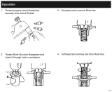
A. Preparing air riveter
Follow the steps below to install the required rivet nozzle:
– Loosen and remove the screw (part 37). To make it easier
to replace the nozzle, unscrew the nozzle holder by 2 or 3
turns (part 38). Then fit the required nozzle (part 37 ~ 37-3)
onto the nozzle holder.
– Loosen the nozzle holder (part 38) and remove it from the
cylinder body (part 53).
– Loosen the clamps holding cone (part 39) from the cone
holding head (part 42).
– Take out the clamp and the clamp opener (parts 40 and 41);
then replace them with the relevant clamp and clamp
opener.
– Then install the clamps holding cone and check adjustment,
so that it can match the caliper wrench (part 63).
– Finally, assemble the nozzle holder and lock it with the
relevant, previously loosened nut.
Fixing problems
Stop using the tool immediately if any of the following problems should occur. Any repair or replacement must be performed by a
trained person or an authorized service centre.
Problem Cause Remedy
Rivet jammed Wrong size of rivet Different rivets require different nozzles, clamps and clamp
openers. Read manual and check rivet size again (fig. 1).
Filings jammed in part 39 Use adjustable wrench or wrench 63 to remove part 38;
then use supplied wrench to remove spare part 39.
Remove any deposits from parts.
Lock parts 38 and 39 (fig. 1).
Filings on part 37 This might occur when aluminium rivets are pulled.
Use a sharp tool to remove filings from part 37.
No suction Shut-off valve has not been opened See fig. 2.
Air leaking Damaged O-rings Replace O-rings.
Loose screws Tighten screws.
Air riveter runs slow Air line is loose Reinstall and tighten airline.
or suffers a loss of
Exhaust port (part 20) is blocked Clean out exhaust port (part 20).
power
Operating pressure is too low Increase operating pressure to 5.9÷6.6 bar.
B. Using air riveter
– Open the air inlet (part 65), to let air into the air riveter.
While using the air riveter, the air inlet (part 65) must be
open, to allow rivet suction.
– Turning the adjusting screw in part 58 allows suction
adjustment. Turning the screw clockwise allows suction to
be reduced.
– Use the nozzle with the relevant rivet; then press the trigger
(part 33) to release the rivet rod into the rivet container (part
59).
– When the rivet container (part 59) is full, unscrew the
adapter (part 61) and empty the rivet container.
– After cleaning it all, screw the adapter (part 61) into the rivet
container (part 59). Then use the air riveter again, following
the steps above.
Tips
Clean parts 38~42 and oil every 500 uses.
Replace parts 40~43 every 2,000 uses (if stainless steel rivets
with Ø 6.4 mm are pulled).
The rivet container (part 59) must be emptied when it reaches
approximately 35 rivets.

LUBRICATION
For optimal use, connect the tool to a filter-lubricator unit
provided with an air-oil microfog mixer (items 1919F...), set at
two drops per minute, pouring special oil ISO 32 (item 1919L)
in. The above-mentioned accessories will translate into a high-
performing tool and wear-resistant mechanical parts.
Do not use kerosene or diesel oil.
MAINTENANCE
Should the riveter be used over long periods of time, impurities
may form on the clamps, thus causing them to slip from the
nail; clean the clamps with either petrol or some degreasers;
then lubricate them.
To lubricate, use Mobilgrease XHP 222.
We recommend replacing any worn clamps.
Regularly check the oil level, as this riveter is an air tool; fill up
whenever a shorter stroke is suddenly shown.
Take the following steps:
1) Disconnect the tool from the feeding plant.
2) Remove the nozzle holder (38).
3) Open the cylinder cover (1).
4) Remove the whole piston unit, using a plier and pulling
without loosening the nut (5).
5) Pour Mobilgrease XHP 222 directly into the body (29), filling
up under part 16.
6) After cleaning and greasing the piston stem and the rubber
piston ring (7-8), put the piston unit back in.
7) Before retightening the nozzle holder, restore the clamps
holding cone (39) and the cone holding head (42) the their
original sizes, using the spanner (63) and the drawing
enclosed with the exploded view. Then connect air and
reighten the nozzle holder keeping the lever (33) pressed.
We recommend using the enclosed exploded view as a manula
to disassemble and assemble the tool as well as to identify any
spare parts.
WARRANTY
This tool is manufactured and tested with the greatest care, in
accordance with current safety regulations, and is covered by a
24-month warranty.
We will repair any breakdowns caused by material or
manufacturing defects by fixing the defective pieces or
replacing them at our discretion. Should assistance be asked
for during the warranty period, the expiry date of this warranty
will remain unchanged.
This warranty will not cover any defects due to wear, misuse,
or breakdowns caused by blows and/or falls. In addition, this
warranty will no longer be valid if any changes are made, or if
the tool is tampered with or sent to the customer service in
pieces.
This warranty explicitly excludes any damage to people and/or
things, whether direct or consequential.
DECLARATION OF CONFORMITY TO THE “MACHINE”
DIRECTIVE
we
BETA UTENSILI SPA
VIA A. VOLTA, 18
20845 SOVICO (MB)
ITALY
hereby certify, assuming full responsability, that the product:
AIR RIVETER
item 1946C 7,8
complies with the following standards, according to the
requirements set by the “Machine Directive”:
2006/42/CE
Place and date of issue
SOVICO (MB) ITALY
January 2014
Name and title of the person in charge
MASSIMO CICERI
(Managing Director)
SPECIFICATIONS
TRACTION POWER 16900 N
STROKE LENGHT 22,5 mm
AIR INLET 1/4” taper GAS
WORKING PRESSURE 6,0 Bars
MAXIMUM WORKING PRESSURE 6,2 Bars
MINIMUM INTERNAL HOSE SIZE 10 mm
MAXIMUM AIR CONSUMPTION 4,9 l
WEIGHT 1,8 Kg
OVERALL LENGTH 305 mm
SOUND PRESSURE 78,5 dB (A)
(pr EN 50144)
SOUND POWER 82,5 dB (A)
(pr EN 50144)
MAXIMUM RIVET CAPACITY 7,8 STEINLESS STEEL
/