
Multi Zone Amplifier
Amplificateur Multizone
XDA-AMP5400RK
OWNER’S MANUAL
MODE D’EMPLOI
MANUAL DE INSTRUCCIONES
ES
FR
EN
UAGLF
(XDA-AMP5400 + Brackets)
(XDA-AMP5400 + Supports)

2 En
BEFORE USING THE UNIT 3
Accessories ..................................................................... 3
About this manual ....................................................... 3
PART NAMES AND FUNCTIONS 4
Front panel ..................................................................... 4
Rear panel ....................................................................... 5
PLACEMENT AND CONNECTION 6
Placing the unit .............................................................6
Mounting the unit on a rack ................................ 6
Placing the unit without a rack........................... 6
Connecting devices .....................................................7
Connecting speakers.............................................. 8
Connecting speakers in bridge mode .............. 8
Connecting external devices ............................... 8
Connecting the power cord................................. 8
Connection examples ............................................ 9
SPECIFICATIONS 13
Specifications .............................................................. 13
CONTENTS

En 3
EN
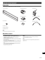
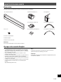
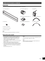
Accessories
Confirm that all the following items are included in the package.
Power cord
Owner’s Manual
Safety Brochure
Note:
Screws for rack mounting are not included.
About this manual
• This OWNER’S MANUAL explains preparations and
operations for installers of the unit. Make sure to deliver this
OWNER’S MANUAL to the user after the placement,
connection and setup of the unit.
• Read the supplied booklet “Safety Brochure” before installing
and using the unit.
• Due to product improvements, specifications and appearance
are subject to change without notice.
• The illustrations in this manual are for instructional purposes
only.
• Access the Yamaha Downloads site to download the latest
Owner’s Manual and Safety Brochure.
http://download.yamaha.com/
Notice:
Indicates precautions for use to avoid the possibility of
malfunction/damage to the unit.
Note:
Indicates instructions and supplementary explanations for
optimum use.
BEFORE USING THE UNIT
Front cover x 1 Euroblock plug x 4 Bracket x 2
Screw x 4
Non-skid pad x 4
Jumper plug x 6
Monaural RCA cable x 2
Control cable x 3

4 En
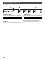
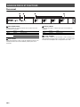
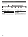
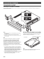
Front panel
a MAIN STATUS indicator
Indicates the unit status depending on its color and whether it is
lit or flashing.
b RESET key
Resets the unit. The unit is restarted forcibly by holding down
RESET key for over 10 seconds.
c STATUS indicators
Indicate the AMP1 - AMP4 status depending on whether they are
lit or flashing.
d STANDBY keys
Set AMP1 - AMP4 to on / standby. The unit consumes a small
power even in standby mode. The unit’s standby power
consumption depends on the standby configuration.
PART NAMES AND FUNCTIONS
ab c
d
– Unlit Standby
White Lit Power on
Red Lit Audio Sense on
Flashing Error occurred
– Unlit Standby
White Lit Power on

En 5
EN
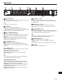
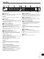
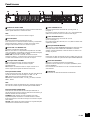
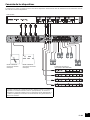
Rear panel
a GND screw terminal
Connecting the source device chassis to the GND terminal of the
unit may reduce noise in the signal.
Note
The ground is not a safety ground.
b IR IN/OUT jack
Connection: 3.5 mm monaural mini-plug
For connecting to an external remote control device and
inputting/outputting remote control signals. The output with pass-
through function is enabled even in standby mode.
c AMP 1– 4: IN/THRU. OUT jacks
Connection: stereo RCA plug (L/R)
IN: For connecting to an audio playback device such as a CD
player (analog out jack) and inputting audio signals in AMP1–
AMP4.
THRU. OUT: For outputting analog audio signals input in
AMP 1– 4 : IN jacks by pass-through function. The output is
enabled even in standby mode.
d AUTO STANDBY switch
Enables/disables the auto-standby function.
OFF: does not set the unit to standby mode automatically.
ON: sets the unit to standby mode when there are no operations
for 8 hours.
AUDIO SENSE switch
Enables/disables the audio sense function that detects analog
audio signals input in AMP 1– 4 : IN.
OFF: disables the audio sense function.
ON: detects the input in AMP 1– 4 : IN, and thereby turns
AMP1– AMP4 to on.
Note
Unplug the unit’s power cord from the AC wall outlet before
changing the AUDIO SENSE switch setting.
AUDIO SENSE MODE switch
Selects the audio sense mode that determines the amount of
time required between input of analog audio signals being
detected and analog audio signals being output.
STANDBY: outputs analog audio signals about 7 seconds after
detecting the input of them. This setting reduces the unit’s
standby power consumption..
ACTIVE: outputs analog audio signals within 1 second after
detecting the input of them.
e TRIGGER IN 1– 4 jacks
Connection: 3.5 mm monaural mini-plug (Tip: + / Sleeve:
-
)
For inputting trigger signals (DC 12 V). Each AMP is powered on
by inputting “High”.
f TRIGGER OUT 1– 4 jacks
Connection: 3.5 mm monaural mini-plug (Tip: + / Sleeve:
-
)
For outputting trigger signals (DC 12 V) iby powering on each
AMP.
g NORMAL/BRIDGE switch
Selects NORMAL/BRIDGE connection of speakers. This switch
is normally set to NORMAL. Change the setting to BRIDGE only
when the speaker is used in bridge connection.
Note
Unplug the unit’s power cord from the AC wall outlet before
changing the NORMAL/BRIDGE switch setting.
h SPEAKERS terminals
Connection: Euroblock connectors (supplied)
Speaker impedance: 4 or over (NORMAL), 8 or over
(BRIDGE)
For connecting to speakers with supplied Euroblock connectors.
i AC IN jack
For connecting the supplied power cord.
i
ad
b
c
e gf
h

6 En
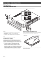
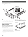
Placing the unit
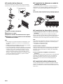
Mounting the unit on a rack
Use the supplied brackets to mount the unit on an EIA standard rack. Screw the brackets to the unit horizontally.
Notice
• Do not use the brackets for devices other than the XDA-
AMP5400.
• When installing brackets, use the included screws.
• Tighten the screws until the brackets are securely fixed.
Note
Screws for rack mounting are not included.
Precautions for rack mounting
If the unit is mounted together with additional units and/or other
devices in an EIA standard equipment rack, the internal
temperature can rise due to heat generated from the devices,
resulting in impaired performance. If the unit is mounted in a rack,
always observe the following requirements to avoid heat buildup:
• If the unit is mounted in a rack with other devices that
generate a significant amount of heat, such as a power
amplifier, leave more than 1U of space between the unit and
other devices (both above and below). Also, make sure to
either leave any open spaces uncovered or install appropriate
ventilating panels to minimize the possibility of heat buildup.
• To ensure sufficient airflow, leave the rear of the rack open
and position it at least 10 cm from walls or other surfaces.
Placing the unit without a rack
Affix the supplied non-skid pads at the four corners on the bottom
of the unit, and then place the unit on a shelf or rack.
Note
Allow ventilation space of at least 10 cm (4 in.) on the top, either
side and back of the unit.
PLACEMENT AND CONNECTION
Without the supplied front cover
With the supplied front cover
Non-skid pads
Bottom face

En 7
EN
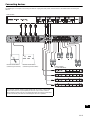
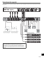
Connecting devices
The following is an example of connecting the devices. Unplug the unit’s power cord from the AC wall outlet before connecting the
devices.
Remote control device
(Infrared signal receiver)
Remote control device
(Infrared signal transmitter)
XDA-QS5400
Power amplifier
(i.e. XDA-AMP5400)
The unit does not have volume controls. Make sure you connect a device with
volume control (such as a pre-amplifier) to the unit. If you connect a device
without volume control (such as a CD player) directly to the unit, the volume may
become excessively loud and result in damage to the unit or speakers.

8 En
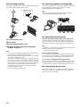
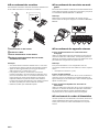
Connecting speakers
Connect the speakers to the unit with the supplied Euroblock plug
and commercially-available speaker cables.
1 Loosen terminal screws.
2 Insert cables.
3 Securely tighten terminal screws.
4 Insert the Euroblock plug into the SPEAKERS
terminals of the unit.
Note
• You must use the supplied Euroblock plugs. If the plugs have
been lost, please contact your Yamaha dealer.
• Recommended cable gauges for the Euroblock plug: AWG26
(0.13 mm
2
) to AWG16 (1.3 mm
2
)
• To prepare the cable for attachment to a Euroblock connector,
strip the wire as shown in the illustration using stranded wire
to make connections. With a Euroblock connection, stranded
wires may be prone to breakage because of metal fatigue due
to the weight of the cable or due to vibration. When rack
mounting your device, use a lacing bar when possible to
bundle and fasten the cables.
• Do not tin (solder) the exposed end.
Connecting speakers in bridge mode
Connect the speakers to the unit with the supplied Euroblock plug
and commercially-available speaker cables, and set the
NORMAL/BRIDGE switch to “BRIDGE”.
Note
Unplug the unit’s power cord from the AC wall outlet before
changing the NORMAL/BRIDGE switch setting.
Connecting external devices
For an external device with analog stereo audio output
Use a commercially-available analog stereo pin cable (stereo
audio RCA cable). You can also use supplied jumper plugs and
monaural RCA cables for various sound system configurations.
Note
For details on the configurations with supplied jumper plugs and
monaural RCA cables, see the following:
• “Connection examples” (p.9)
For a remote control device
Use a commercially-available 3.5 mm monaural mini-plug cable.
For connecting to an infrared signal receiver/emitter that allows
you to operate the unit and other devices from another room.
For a device compatible with the trigger function
Use a commercially-available 3.5 mm monaural mini-plug cable.
The trigger function can be controlled by external devices (such
as XDA-QS5400) in conjunction with powering on/off the device.
Connecting the power cord
After all the connections are complete, plug the supplied power
cord into the AC IN jack on the rear panel, and then plug the
power cord to an AC wall outlet.
d
a
b
c
Approx. 5 mm
(approx. 1/4")

En 9
EN
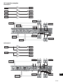
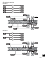
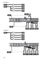
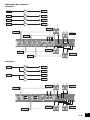
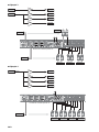
Connection examples
Example 1
Example 2
Source1
Source2
Source3
Source4
Speaker1
Speaker2
Speaker3
Speaker4
AMP1
AMP2
AMP3
AMP4
Speaker1
Speaker2
Speaker3
Speaker4
Source2
Source4
Source1
Source3
L
R
L
R
L
R
L
LR
LR
LR
LR
R
Source1
Source2
Speaker1
Speaker2
Speaker3
Speaker4
AMP1
AMP2
AMP3
AMP4
Source1
Source2
L
R
L
R
LR LR
LR LR
Speaker1
Speaker3
Speaker2
Speaker4
Jumper plug x 4

10 En
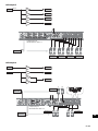
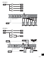
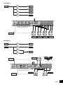
Example 3
Example 4
Source1
Source2
Speaker1
Speaker2
Speaker3
Speaker4
AMP1
AMP2
AMP3
AMP4
Source1
Source2
L
LR
LR LR LR
R
L
R
Speaker1
Speaker2 Speaker3 Speaker4
Jumper plug x 4
Stereo
Source1
Speaker1
Speaker2
Speaker3
Speaker4
AMP1
AMP2
AMP3
AMP4
Source1
LR LR LR LR
L
R
Speaker1 Speaker2 Speaker3 Speaker4
Jumper plug x 6

En 11
EN
Example 5
Example 6
Mono
Source1
Speaker1
Speaker2
Speaker3
Speaker4
AMP1
AMP2
AMP3
AMP4
Source1
Mono
Mono Mono Mono Mono Mono Mono Mono Mono
Speaker1 Speaker2 Speaker3 Speaker4
Jumper plug x 6
Monaural RCA cable x 1
Source1
Source2
Speaker1
Speaker2
Speaker3
AMP1
AMP2
AMP3
AMP4
Source1
Source2
L
R
L
R
LR
LR LR
Speaker1
Speaker2 Speaker3
Jumper plug x 1
Monaural RCA cable x 1
(High Power)

12 En
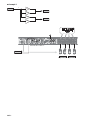
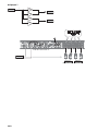
Example 7
L
R
Source1
Speaker1
Speaker2
AMP1
AMP2
AMP3
AMP4
Source1
LRLR
L
R
Speaker1 Speaker2
Monaural RCA cable x 2
(High Power) (High Power)

En 13
EN
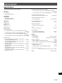
Specifications
The specifications of the unit are as follows.
Input jacks
Analog Audio
• Stereo Audio (RCA) x 4
Output jacks
Analog Audio
• Speaker Out x 4 (L/R)
• Stereo Audio (RCA) x 4
Other jacks
Trigger In x 4
Trigger Out x 4
Remote In x 1
Remote Out x 1
Audio Section
Rated Output Power
• (2-channel driven, 1 kHz, 0.9% THD, NORMAL, 4/8 )
90/50 W
• (2-channel driven, 1 kHz, 0.9% THD, BRIDGE, 8 ) 100 W
• (1-channel driven, 1 kHz, 0.9% THD, NORMAL, 4/8 )
100/50 W
• (1-channel driven, 1 kHz, 0.9% THD, BRIDGE, 8 ) 200 W
Dynamic Power
• (2-channel driven, 20 Hz to 20 kHz, 0.08% THD,
20ms Burst, NORMAL, 4/8 ) 80/40 W
• (2-channel driven, 20 Hz to 20 kHz, 0.08% THD,
20ms Burst, BRIDGE, 8 ) 150 W
• (2-channel driven, 1 kHz, 0.9% THD, 20ms Burst,
NORMAL, 4/8 ) 100/50 W
• (2-channel driven, 1 kHz, 0.9% THD, 20ms Burst,
BRIDGE, 8 ) 200 W
• (All channel driven, 1 kHz, 0.9% THD, 20ms Burst,
NORMAL(8-ch), 4/8 ) 80/50 W
• (All channel driven, 1 kHz, 0.9% THD, 20ms Burst,
BRIDGE(4-ch), 8 ) 170 W
Maximum Effective Output Power (JEITA)
• (1-channel driven, 1 kHz, 10% THD, NORMAL, 4/8 )
130/65 W
• (1-channel driven, 1 kHz, 10% THD, BRIDGE 8 ) 260 W
Total Harmonic Distortion (THD)
• (20 Hz to 20 kHz, SP OUT, 25 W, 8 ) 0.04% THD
Frequency Response (+0/
-
3 dB)
• SP OUT (AMP IN) 5 Hz to 40 kHz
Signal to Noise Ratio (IHF-A)
• SP OUT (AMP IN) 108 dB
Maximum Input Signal
• AMP IN (1 kHz, 0.9% THD) 1.0 V
Gain
• SP OUT (1 V INPUT) 25.8 dB
Input Sensitivity
• 1 W power (1 W/8 output) 150 mV
• MAX power (50 W/8 output) 1.0 V
General
Power Supply
• [U.S.A. model] AC 120 V, 60 Hz
• [Other models] AC 220 to 240 V, 50/60 Hz
Power Consumption 130 W
• Amp1 - Amp4 On, No Signal Condition 32 W
• Amp1 - Amp4 Off, Audio Sense On, Audio Sense Mode Active
14.8 W
Standby Power Consumption
• Audio Sense Off 0.3 W
• Audio Sense On, Audio Sense Mode Standby 0.5 W
Dimensions (W x H x D)
437 x 46 x 443 mm (17-1/4” x 1-3/4” x 17-3/8”)
Weight 6.0 kg (13.2 lbs)
SPECIFICATIONS

14 En
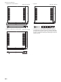
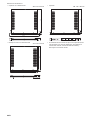
Reference Dimensions
• Brackets with front cover
481 x 44 x 453 mm (18-7/8" x 1-3/4" x 17-7/8")
• Table Top Mount-with front cover
437 x 46 x 453 mm (17-1/4" x 1-3/4" x 17-7/8")
• Brackets
481 x 44 x 443 mm (18-7/8" x 1-3/4" x 17-3/8")
* The contents of this manual apply to the latest specifications
as of the publishing date. To obtain the latest manual, access
the Yamaha website then download the manual file.
44
1-3/4"
481
18-7/8"
453
17-7/8"
5.0
1/4"
437
443
17-3/8"
44
1-3/4"
46
1-3/4"
453
17-7/8"
17-1/4"
481
18-7/8"
443
17-3/8"
5.0
1/4"
44
1-3/4"
Page is loading ...
Page is loading ...
Page is loading ...
Page is loading ...
Page is loading ...
Page is loading ...
Page is loading ...
Page is loading ...

Fr 23
FR
Exemples de connexion
Exemple 1
Exemple 2
Source 1 Enceinte 1
AMP1
Source 2 Enceinte 2
AMP2
Source 3 Enceinte 3
AMP3
Source 4 Enceinte 4
AMP4
Source 1
Source 2
Source 3
Source 4
Enceinte 1
Enceinte 2
Enceinte 3
Enceinte 4
G D
G D
G D
G D
G
D
G
D
G
D
G
D
Connecteur cavalier x 4
Source 1 Enceinte 1
AMP1
Enceinte 2
AMP2
Source 2 Enceinte 3
AMP3
Enceinte 4
AMP4
G D
G D
Enceinte 1
Enceinte 2
Enceinte 3
Enceinte 4
Source 1
Source 2
G
D
G
D
G DG D

24 Fr
Exemple 3
Exemple 4
Connecteur cavalier x 4
Source 1 Enceinte 1
AMP1
Source 2 Enceinte 2
AMP2
Enceinte 3
AMP3
Enceinte 4
AMP4
G
D
G
D
G D
G D
G D
G D
Source 1
Source 2
Enceinte 1
Enceinte 2
Enceinte 3
Enceinte 4
Connecteur cavalier x 6
Source 1 Enceinte 1
AMP1
Enceinte 2
AMP2
Enceinte 3
AMP3
Enceinte 4
AMP4
G
D
Source 1
Enceinte 2
Enceinte 3
Enceinte 4
Enceinte 1
G D
G D
G D
G D
Stereo
Page is loading ...
Page is loading ...
Page is loading ...
Page is loading ...
Page is loading ...
Page is loading ...
Page is loading ...
Page is loading ...
Page is loading ...
Page is loading ...
Page is loading ...
Page is loading ...
Page is loading ...
Page is loading ...
Page is loading ...
Page is loading ...
Page is loading ...
Page is loading ...
Page is loading ...

Published 12/2018 NVEM-C0
© 2018 Yamaha Corporation
Manual Development Group
Yamaha Global Site
https://www.yamaha.com/
Yamaha Downloads
https://download.yamaha.com/
VCM9320
-
 1
1
-
 2
2
-
 3
3
-
 4
4
-
 5
5
-
 6
6
-
 7
7
-
 8
8
-
 9
9
-
 10
10
-
 11
11
-
 12
12
-
 13
13
-
 14
14
-
 15
15
-
 16
16
-
 17
17
-
 18
18
-
 19
19
-
 20
20
-
 21
21
-
 22
22
-
 23
23
-
 24
24
-
 25
25
-
 26
26
-
 27
27
-
 28
28
-
 29
29
-
 30
30
-
 31
31
-
 32
32
-
 33
33
-
 34
34
-
 35
35
-
 36
36
-
 37
37
-
 38
38
-
 39
39
-
 40
40
-
 41
41
-
 42
42
-
 43
43
-
 44
44


Yamaha XDA-AMP5400RK Owner's manual
- Type
- Owner's manual
- This manual is also suitable for
Ask a question and I''ll find the answer in the document
Finding information in a document is now easier with AI
in other languages
- italiano: Yamaha XDA-AMP5400RK Manuale del proprietario
- français: Yamaha XDA-AMP5400RK Le manuel du propriétaire
- español: Yamaha XDA-AMP5400RK El manual del propietario
- Deutsch: Yamaha XDA-AMP5400RK Bedienungsanleitung
- русский: Yamaha XDA-AMP5400RK Инструкция по применению
- Türkçe: Yamaha XDA-AMP5400RK El kitabı
- svenska: Yamaha XDA-AMP5400RK Bruksanvisning