
GB
DRAWING DESSIN ZEICHNUNG
DISEGNO TEKENING
DRAWING DESSIN ZEICHNUNG
DISEGNO TEKENING
GB DESCRIPTION
FR DESCRIPTION
DE BESCHREIBUNG
IT DESCRIZIONE
NL BESCHRIJVING
Date: 2017-08-22
123620-280 Rev B ECN 276816
Page 1 of 6 www.asco.com
Installation and Maintenance instructions
ameproof solenoid operator (WSNFX - MXX)
GENERAL
This installation and maintenance
instruction sheet of the solenoid is a general
supplement to the particular I&M sheet for
the valve. The identification is made by
prex WSNFX to the catalogue number.
Always use both I&M sheets for installing
and maintaining the solenoid valve.
DESCRIPTION
The solenoid valves are designed in
accordance with annex II of the European
directive 2014/34/EU. EC type examination
certificate FTZÚ 04 ATEX 0213X in
compliance with the international and
European standards
ATEX
EN 13463-1
EN 60079-0
EN 60079-1
Classication:
I M2 Ex db I Mb IP66/67.
INSTALLATION
ASCO components are intended to be used
only within the technical characteristics as
specied on the nameplate. Changes to the
equipment are only allowed after consulting
the manufacturer or its representative.
These solenoid valves are intended for
installation in potentially explosive mine
atmospheres, Group I, Category M2.
Depending on the ambient temperature/
wattage, a heat resistant cable, suitable for
temperature as indicated on the nameplate,
must be used. This equipment is intended to
be de-energized in the event of an explosive
atmosphere. The means of protection relating
to equipment in this category assure the
requisite level of protection during normal
operation and also in the case of more severe
operating conditions, in particular those
arising from rough handling and changing
environmental conditions.
ELECTRICAL INSTALLATION
Wiring must comply with local and national
regulations of explosion proof equipment.
For the cable/conduit entry, the enclosure
is provided with a ½” NPT or M20x1,5
threaded hole. Entry of external conductors
and cables must be through properly installed
and suitable certied for potentially explosive
mine atmosphere ameproof cable entry
devices. To make connection to the coil
terminals, remove solenoid cover. Strip the
outer insulation of the cable over approx.
150 mm and the insulation from the leads
over 8 mm. Insert wires through the cable
gland and connect wires to the terminals
of the coil. Connect cable ground wire to
the internal ground terminal. Keep some
slack in the leads between cable entry and
coil to avoid excessive strain on the leads.
Assemble the cable gland and tighten the
elastomer compression seal so that it ts
tightly around the cable. When the set screw
is unscrewed, the solenoid can be rotated
360° to select the most favorable position
for the cable entry. Close the enclosure and
tighten 4 cover screws securely to torque
indicated. The solenoid housing is provided
with an external connection facility for an
earthing or bonding conductor.
CAUTION
Electrical load must be within the range stated
on the nameplate. Failure to stay within the
electrical range of the coil rating results in
damage to or premature failure of the coil.
It will also invalidate the approval. WARNING:
It is not permitted to have the solenoid
cover removed by unauthorized personnel.
The spigot of the solenoid cover and the
bore in the solenoid housing constitute the
tightly toleranced amepath of the ameproof
solenoid. When removing or re-assembling the
solenoid cover, utmost care should be taken to
avoid any damage to either the spigot or the
bore. Do not paint these surfaces. However,
some grease or lubricant may be sparingly
applied.
SERVICE
To prevent the possibility of personal or
property damage, do not touch the solenoid.
It can become hot under normal operation
conditions. If the solenoid valve is easily
accessible, the installer must provide
protection preventing accidental contact.
MAINTENANCE
Maintenance depends on service conditions.
Periodic cleaning is recommended, the
timing of which will depend on the media
and service conditions. During servicing,
components should be examined for
excessive wear. A complete set of internal
parts is available as a spare parts kit.
If a problem occurs during installation/
maintenance or in case of doubt please
contact ASCO or authorized representative.
CAUTION: Before servicing the solenoid
valve, turn off electrical power, depressurize
valve and vent uid to a safe area. Do not
open the solenoid when energized recently,
delay opening for 35 minutes. Solenoid must
be fully reassembled as the housing and
internal parts complete the magnetic circuit.
At screw Nr 1 replacement: use only screws
with 700 N/mm2 minimum tensile strength.
In case of any replacement of parts by the
user, the traceability of the final product
can not be guaranteed by ASCO. Wrong
assembly will invalidate the approval.
SOLENOID/VALVE (DIS)-ASSEMBLY
Tighten the set screw, (un)screw the
complete solenoid (from)/to the valve by
means of a hook spanner.
For additional information visit our
internet site: www.asco.com
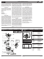
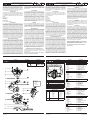
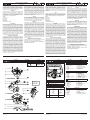
1. Screw
2. Cover
3. O-ring
4. Clip
5. Plate
6. Washer, spring
7. Coil
8. Yoke
9. Housing
10. Cable entry
11. Set screw
12. Hook wrench
13. Washer, spring (2x)
14. Screw (2x)
15. Mounting bracket
1. Vis
2. Couvercle
3. Joint torique
4. Clip
5. Plaque
6. Rondelle élastique,
ressort
7. Bobine
8. Culasse
9. Boîtier
10. Entrée de câble
11. Vis de l’ensemble
12. Clé à crochet
13. Rondella élastique (2x)
14. Vis (2x)
15. Support de montage
1. Schraube
2. Deckel
3. Dichtungsring
4. Klammer
5. Platte
6. Federscheibe
7. Magnetspule
8. Joch
9. Gehäuse
10. Kabeleinführung
11. Einstellschraube
12. Hakenschlüssel
13. Federscheibe (2x)
14. Schraube (2x)
15. Montagehalterung
1. Vite
2. Coperchio
3. Anello di ritenuta
4. Clip
5. Targhetta
6. Rondella, molla
7. Bobina
8. Giogo
9. Sede
10. Ingresso del cavo
11. Vite di fermo
12. Chiave per dadi
13. Rondella elastica (2x)
14. Vite (2x)
15. Squadra di ssaggio
1. Bout
2. Deksel
3. O-ring
4. Bevestigingsclip
5. Plaat
6. Veerring
7. Spoel
8. Juk
9. Huis
10. Kabeldoorvoer
11. Stelschroef
12. Haaksleutel
13. Veering (2x)
14. Schroef (2x)
15. Montagebeugel
TORQUE CHART
A
B
C
D
E
F
G
7 ± 0,5
1,5 ± 0,2
1 ± 0,2
0,5 ± 0,1
20 ± 3
15 ± 2
4 ± 0,5
62 ± 5
12 ± 2
8 ± 2
4 ± 1
175 ± 25
135 ± 15
35 ± 5
ITEMS NEWTON.METRES INCH.POUNDS
GB
Supplied in spare part kit
FR
Livrées en pochette de rechange
DE
Enthalten im Ersatzteilsatz
IT
Disponibile nel Kit parti di ricambio
NL
Geleverd in vervangingsset
GB optional
FR en option
DE optional
IT facoltativo
NL optioneel
SERIES
WSNFX - MXX
Page is loading ...
Page is loading ...
Page is loading ...
Page is loading ...
Page is loading ...
-
 1
1
-
 2
2
-
 3
3
-
 4
4
-
 5
5
-
 6
6


Ask a question and I''ll find the answer in the document
Finding information in a document is now easier with AI
in other languages
- italiano: Asco Series WSNF Solenoid Manuale del proprietario
- français: Asco Series WSNF Solenoid Le manuel du propriétaire
- español: Asco Series WSNF Solenoid El manual del propietario
- Deutsch: Asco Series WSNF Solenoid Bedienungsanleitung
- Nederlands: Asco Series WSNF Solenoid de handleiding
- português: Asco Series WSNF Solenoid Manual do proprietário
- dansk: Asco Series WSNF Solenoid Brugervejledning
- polski: Asco Series WSNF Solenoid Instrukcja obsługi
- čeština: Asco Series WSNF Solenoid Návod k obsluze
- svenska: Asco Series WSNF Solenoid Bruksanvisning
- suomi: Asco Series WSNF Solenoid Omistajan opas
Related papers
-
Asco Series WSNFX Solenoid M12-I User manual
-
-
-
-
-
-
-
-
Asco Series WPIS WSIS Solenoid M12 Low Power User manual
-
