
Instructions
For series progressive, oil and grease lubrication. For Professional Use Only.
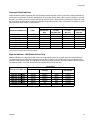
Models/Maximum Pressure
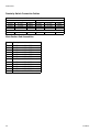
Table 1: Maximum Pressure Lube Points Table 2: MGO Series-Flo Divider Maximum
Operating Pressures
Important Safety Instructions
Read all warnings and instructions in this
manual. Keep these instructions.
Divider Type
Maximum
Operating
Pressure kPSI
(MPa, bar)
Maximum
Sections
MD 3.0 (20.7, 207) 2
MJ 2.0 (13.8, 138) 8
MSP/MSPSS 3.5 (24.1, 241) 8
MHH 7.5 (51.7, 517) 8
MX 3.0 (20.7, 207) 10
MXP 3.0 (20.7, 207) 10
MGO See Table 2 11
Maximum Operating
Pressure kPSI (MPa, bar)
Number of Sections
6.0 (41.4, 414) 3 to 7
5.5 (37.9, 379) 8
4.0 (27.6, 276) 9
4.5 (31.0, 310) 10
4.0 (27.6, 276) 11
312497P
EN
Trabon
Divider Valves

Warnings
2 312497P
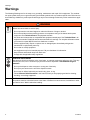
Warnings
The following Warnings are for the setup, use, grounding, maintenance and repair of this equipment. The exclama-
tion point symbol alerts you to a general warning and hazard symbols refer to procedure-specific risks. Refer back to
these Warnings. Additional, product-specific warnings may be found throughout the body of this manual where appli-
cable.
WARNING
EQUIPMENT MISUSE HAZARD
Misuse can cause death or serious injury.
• Do not operate the unit when fatigued or under the influence of drugs or alcohol.
• Do not exceed the maximum working pressure or temperature rating of the lowest rated system
component. See Technical Data in all equipment manuals.
• Use fluids and solvents that are compatible with equipment wetted parts. See Technical Data in all
equipment manuals. Read fluid and solvent manufacturer’s warnings. For complete information about
your material, request MSDS forms from distributor or retailer.
• Check equipment daily. Repair or replace worn or damaged parts immediately with genuine
manufacturer’s replacement parts only.
• Do not alter or modify equipment.
• Use equipment only for its intended purpose. Call your distributor for information.
• Keep children and animals away from work area.
• Comply with all applicable safety regulations.
SKIN INJECTION HAZARD
High-pressure fluid from dispense valve, hose leaks, or ruptured components will pierce skin. This may
look like just a cut, but it is a serious injury that can result in amputation. Get immediate surgical
treatment.
• Do not point dispense valve at anyone or at any part of the body.
• Do not put your hand over the end of the dispense nozzle.
• Do not stop or deflect leaks with your hand, body, glove, or rag.
• Follow Pressure Relief Procedure in this manual, when you stop spraying and before cleaning,
checking, or servicing equipment.
CALIFORNIA PROPOSITION 65
This product contains a chemical known to the State of California to cause cancer, birth defects or other
reproductive harm. Wash hands after handling.

Setup
312497P 3
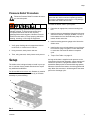
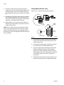
Pressure Relief Procedure
Follow the Pressure Relief Procedure whenever
you see this symbol.
1. Verify pump feeding valve is stopped and discon-
nected from, or locked out of it’s driver.
2. Using a wrench, slowly loosen inlet nut.
3. Then, using a wrench, slowly loosen each port nut.
Setup
The divider valve is shipped ready to install in your sys-
tem. It has been factory-tested and should not require
any additional modification.
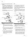
For MJ and MX series valves only
: Gaskets (a) must be
installed between every valve section (b) of the block
assembly to prevent leaking.
To install the divider valve in your system:
1. Determine an appropriate, remote mounting loca-
tion.
2. Install a rupture to atmosphere fitting with a blow-out
disk that is rated for 7,500 psi (52 MPa, 517 bar) or
less between the force feed lubricator pump and
master divider valve inlet.
3. Install an analog pressure gauge at the inlet to the
divider valve.
4. Install a slow or no cycle shutdown in one of the pis-
ton enclosure plugs. Program it to shut down after
no more than 180 seconds without a complete
cycle.
5. Torque. See Table 4 on page 15.
As long as lubricant is supplied under pressure to the
inlet section of the divider assembly, valves sections will
continue to operate in a progressive manner. Divider
assemblies always follow a constant discharge pattern.
Whenever lubricant flow ceases, the valving pistons will
stop. When flow resumes, it will start again at the same
point in the discharge cycle.
This equipment stays pressurized until pressure is
manually relieved. To help prevent serious injury
from pressurized fluid, such as skin injection,
splashing fluid and moving parts, follow the Pressure
Relief Procedure when you stop spraying and before
cleaning, checking, or servicing the equipment.
FIG. 1
a
b
b
NOTICE
Do not install a divider valve into a system rated for
more than the valve’s maximum operating pressure.
This type of installation could result in o-ring damage
and cause the divider valve to leak.

Setup
4 312497P
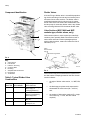
Component Identification
Key:
A Valve Section
B Inlet Section
C Indicator / Port Plug
D Crossport Plate
E End Plug
F Subplates with Outlet Ports
G End Section
H Tie Rod Nut
Table 3: Typical Divider Valve
Combinations
Divider Valves
A Series-Flo type divider valve is a manifold proportion-
ing device consisting of an inlet and end section plus a
minimum of three valve sections. The divider valve is
manifolded together with tie rods and nuts. A master
divider valve is the first divider valve downstream from
the lube pump. A secondary divider valve is any divider
valve receiving lubricant from the master divider valve.
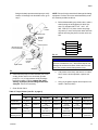
Valve Sections (MSP, MHH and MXP
modular-type, divider valves, only)
Valve sections (three or more required per manifold)
contain a piston specially fitted to that section, built in
outlet check valves and various passageways that,
working with the piston, meters and valves the flow of
lubricant (F
IG. 3).
Valve sections may be manufactured to require one or
two lube outlets. Stamping located on the face of each
section indicates:
• the style of divider valve section, i.e., MSP, MX,
etc.,
• the discharge per piston stroke expressed in
thousandths of cubic inches (35 = .035 in
3
)
and,
• the number of lube outlets required (S = single,
one outlet only; T = twin, two lube outlets
required).
FIG. 2
MASTER SECONDARY
TYPE OF
APPLICATION
MJ MD Machine tools, Printing,
Wire Forging &
Packaging Machinery
MSP MJ, MSP Machine tools, Textile,
Glass & Can Machinery,
Mobile Equipment
MX, MXP MX, MXP, MSP Cranes, Presses, Steel
Mills, etc.
MGO MX Levellers, Shears,
Conveyors, etc.
A
B
C
D
E
F
G
H
FIG. 3
TI11102
Piston
Enclosure/End
Enclosure Plug Gasket
Piston
Indicator
Indicator Port Plug
Port
O-Rings
Check
Valve
Plug

Setup
312497P 5
Prefilling Lubricant Distributor Lines
Follow the following procedure exactly as written, in the
order written.
Filling Secondary-to-Lube Point Lines
Refer to FIG. 4. when performing this procedure
.
1. Remove port plugs or performance indicators from
all of the indicator ports on front of secondary
divider valves.
2. Connect a hand pump filled with clean, filtered lubri-
cant to the indicator port closest to the first line to be
filled that corresponds to the output port that is feed-
ing the line to be filled.
3. In order to verify when lubricant is flowing and has
reached the end of the lube line, loosen the connec-
tor at the lube point of the line that is to be filled.
4. Stroke the hand pump until air-free lubricant is
observed flowing from the end of the lube line.
5. Tighten the lube line connector at the lube point, but
do not replace the port plugs or performance indica-
tors into the ports on the front of the working sec-
tion.
6. Repeat steps 1-5 for each of the other lube lines
connected to the other outlet ports in the secondary
divider valve assembly and for any other secondary
divider assemblies in the system.
NOTE: Do not replace any of the performance indica-
tors or port plugs removed in Step 1 until the line-filling
procedure described in Section 2 (Filling Master
-to-Secondary Lube Lines) has been completed.
Filling Master-to-Secondary Lube Lines
Refer to FIG. 5. when performing this procedure.
1. Remove the port plugs or performance indicators
from all the indicator ports on the front of the master
divider valve.
2. Connect a hand pump filled with clean, filtered lubri-
cant to the indicator port closest to the lube output
port that is feeding the line to the secondary divider
valve.
3. Stroke the hand pump to fill the line between the
master divider valve and secondary divider valve.
NOTICE
• The initial startup and operation is the most critical
operating period for a newly installed machine in
terms of potential for being damaged by unre-
moved/unfiltered lubricant contaminants and lack of
adequate lubrication. Proper prefilling of lubrication
system ensures that lubricant is immediately avail-
able to every lube point during machine startup,
protecting them from damage.
• Use only clean oil filtered to the SAE -recom-
mended cleanliness level of ISO 18/14 (ISO Stan-
dard 4406) when prefilling a system. The
manufacturers of the machine tool and its compo-
nent bearings should be consulted to ensure that
the ISO 18/14 cleanliness level is adequate.
FIG. 4
TI11098
MASTER
HAND PUMP
BLEED HOSE
REMOVE INDICATOR
OR PORT PLUG
SECONDARY
LUBE POINT
HERE
FIG. 5
TI11099
MASTER
SECONDARY
LUBE POINT
REMOVE INDICATOR
OR PORT PLUG
HAND PUMP
BLEED
ALL PORTS
THROUGH

Setup
6 312497P
4. Continue to stroke the pump until the lubricant
purges all the air out of the internal passages of the
secondary divider valve and lubricant flows freely
from all indicator ports with no evidence of included
air.
5. Reinstall the port plugs or performance indicators in
their respective positions in the secondary divider
valve. Do not replace the port plugs or performance
indicators in the master divider valve yet.
6. Repeat Steps 1-5 for each of the other lube lines
between the master divider valve and all other sec-
ondary divider valves.
NOTE: Do not replace any of the performance indica-
tors or port plugs removed in Step 1 from the master
divider valve assembly until the air-purging procedure
described in Section 3 (Filling Master Divider Valve) has
been completed.
Filling Master Divider Valve
Refer to FIG. 6. when performing this procedure.
1. Verify that all port plugs or performance indicators
have been removed from all indicator ports in the
master divider valve.
2. Verify that the system pump is properly connected
to the inlet port of the master divider valve.
3. Cycle the system pump sufficiently to fill the main
feeder line between the pump and the master
divider valve and the lubricant is observed being
discharged from all of the indicator ports on the front
of the master divider valve with no evidence of
included air.
4. Reinstall the master divider valve port plugs or per-
formance indicators into their respective positions.
FIG. 6
TI11000
MASTER
BLEED
SECONDARY
LUBE POINT
HERE
CYCLE PUMP

Repair
312497P 7
Repair
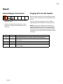
General Repair Instructions
• Before performing any repair procedures, relieve
pressure, page 3.
• Pressure test distribution blocks yearly or every
8000 hours. Replace seals and divider valves as
necessary.
Purging Air From the System
Before machine operation is resumed following mainte-
nance or repair, manual system air purging must be per-
formed.
There are several air purging procedures available
depending upon the maintenance or repair procedure.
NOTE: Use only clean oil filtered to the SAE -recom-
mended cleanliness level of ISO 18/14 (ISO Standard
4406) when prefilling a system. The manufacturers of
the machine tool and its component bearings should be
consulted to ensure that the ISO 18/14 cleanliness level
is adequate.
Page Section Air purging after:
8 1 Replacing line between a secondary divider valve and lube point.
9 2 Replacing a line between the master divider valve and a secondary
divider valve.
10 3 Replacing a line between pump and master divider valve.
11 4 Adding or replacing any component in a master divider valve assembly.
12 5 Adding or replacing any component in module in a secondary divider
valve assembly.

Repair
8 312497P
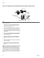
Section 1: Purging Air from Secondary Divider Valve Lube-to-Lube Point Lines
Steps 1-6, refer to FIG. 7.
1. Install the line from the secondary divider valve to
the lube point, but do not completely tighten the
connection at the lube point.
2. Remove the performance indicator port plug or the
performance indicator from the working valve sec-
tion on the secondary divider valve assembly corre-
sponding to the outlet port and the line connected to
the lube point.
3. Attach a hand pump filled with clean, filtered lubri-
cant to the port on the secondary divider valve that
was opened in Step 2.
4. Operate the hand pump until air-free lubricant is
observed flowing from the line at the lubrication
point.
5. Tighten the fitting at the lubrication point while lubri-
cant is still flowing.
6. Remove the hand pump and reinstall the perfor-
mance indicator or indicator port plug removed in
Step 2.
NOTE: If check valves were not installed at the lubrica-
tion point, lubricant may continually drain out of the line
when the secondary port is open. Therefore, when
check valves are not used, the method for bleeding this
line is to tighten the line at both ends and repeatedly
cycle the secondary divider valve via hand pump opera-
tion until lubricant, free of air, flows from the lubrication
point
FIG. 7
TI11098
MASTER
HAND PUMP
BLEED HOSE
REMOVE INDICATOR
OR PORT PLUG
SECONDARY
LUBE POINT
HERE

Repair
312497P 9
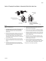
Section 2: Purging Air from Master to Secondary Divider Valve Lube Lines
Steps 1- 9, refer to FIG. 8.
1. Install the lines from the master divider valve to the
secondary divider valve, but do not completely
tighten the connection at the secondary divider
valve’s inlet.
2. Remove the performance indicator port plug or the
performance indicator from the working valve sec-
tion on the master divider valve assembly corre-
sponding to the outlet port and the line connected to
the secondary valve.
3. Attach a hand pump filled with clean, filtered lubri-
cant on the master divider valve that was opened in
Step 2.
4. Operate the hand pump until air-free lubricant is
observed flowing freely from the secondary valve’s
lube inlet connector.
5. Tighten the fitting at the secondary valve’s inlet
while lubricant is still flowing.
6. Remove all of the indicators or indicator port plugs
from the secondary divider valve’s working sections.
7. Operate the hand pump again until air-free lubricant
is observed flowing out of all the secondary divider
valve’s indicator ports.
8. Reinstall all of the performance indicators or port
plugs in the secondary divider valve while lubricant
is still flowing from the ports.
9. Remove the hand pump and reinstall the perfor-
mance indicator or indicator plug removed in Step 2
into the master divider working valve’s open port.
The system is now ready for operation.
FIG. 8
TI11113
MASTER
HAND PUMP
REMOVE INDICATOR
OR PORT PLUG
SECONDARY
LUBE POINT
BLEED HERE
FIRST
AFTER BLEEDING INLET,
REMOVE ALL INDICATORS
OR PORT PLUGS AND BLEED
ALL PORTS

Repair
10 312497P
Section 3: Purging Air from Pump to Master Divider Valve Lines
Steps 1-3, refer to FIG. 9.
1. Install the line from the system pump to the master
divider valve, but do not completely tighten the con-
nection at the master valve’s lube inlet.
2. Cycle the system pump until air-free lubricant is
observed flowing from the line at the master divider
valve’s lube inlet.
3. Tighten the fitting at the lube inlet port while lubri-
cant is still flowing.
The system is now ready for operation.
FIG. 9
TI11114
BLEED THROUGH
SECONDARY
MASTER
ALL PORTS
SYSTEM PUMP
LUBE POINT

Repair
312497P 11
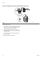
Section 4: Purging Air After Adding or Replacing a Master Divider Valve Module
Steps 1-7, refer to FIG. 10.
1. Install the new or replacement module into the mas-
ter divider valve assembly. Also connect the tubing
or hoses to the appropriate secondary divider
valve(s) or lubrication point(s) if the new/replace-
ment module is a base section.
2. Do not completely tighten the connection(s) at the
secondary divider valve’s inlet or at lubrication
points.
3. Disconnect and remove the line from the pump at
the inlet of the master divider valve.
4. Attach a hand pump filled with clean, filtered lubri-
cant to the inlet port on the master divider valve.
5. Operate the hand pump until air-free lubricant is
observed flowing from each secondary valve’s lube
inlet connector and/or each lubrication point’s con-
nector.
6. Tighten the fitting at the secondary valve inlet or at
the lubrication port while lubricant is still flowing.
7. Remove the hand pump and reconnect the system
pump to the inlet of the master divider valve.
The system is now ready for operation.
FIG. 10
TI11116
BLEED
SECONDARY
MASTER
HAND PUMP
LUBE POINT
DISCONNECT
LINE
HERE
NEW VALVE
BLOCK

Repair
12 312497P
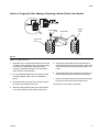
Section 5: Purging Air After Adding or Replacing a Secondary Divider Valve Module
Steps 1-8, refer to FIG. 11.
1. Install the new or replacement module to the sec-
ondary divider valve assembly. Also connect the
tubing or hoses to the appropriate lubrication point if
the new/replacement module is a base section.
2. Do not completely tighten the connection(s) at the
lubrication point.
3. Remove the performance indicator or indicator port
plug from the working valve section on the second-
ary divider valve assembly corresponding to the out-
let port and line connected to a particular lube point.
4. Attach a hand pump filled with clean, filtered lubri-
cant to the port on the secondary divider valve that
was opened in Step 3.
5. Operate the hand pump until air-free lubricant is
observed flowing from the loosened connector at
the lube point.
6. Tighten the fitting at the lube point while lubricant is
still flowing.
7. Repeat Steps 3 - 6 for any additional lubrication
points connected to the new module.
8. Remove the hand pump and reinstall the perfor-
mance indicator or port plug removed in Step 3 into
the secondary divider valve’s open port.
The system is now ready for operation.
FIG. 11
TI11115
MASTER
HAND PUMP
BLEED HOSE
REMOVE INDICATOR
OR PORT PLUG
SECONDARY
LUBE POINT
HERE
NEW VALVE
BLOCK
BLEED
HERE

Repair
312497P 13
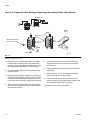
Locating and Repairing
Blockages
Blocks will cause a higher than normal pumping pres-
sure. Depending on the application or system design,
this blockage will usually result in a complete loss of
lubricant flow into the total system and no bearing will be
receiving lubrication.
The loss of flow due to a blockage is first indicated with
the higher than normal system pressure that is devel-
oped by the pump as it attempts to overcome this block-
age. Higher pressure is limited, isolated and signaled
through the use of various performance indicators, reset
and relief, incorporated into the system design.
Performance Indicators
Performance indicators are pressure-sensitive devices
that pinpoint excessive pressure in the lubricating sys-
tem.
These devices are installed in the indicator ports of
divider valves, signal a fault either by causing an indica-
tor pin to protrude or by releasing lubricant into the
atmosphere.
NOTE: Never block a lube outlet that is designed to dis-
charge lubricant.
Reset Indicator with Memory
Reset indicators stop lube system operation when a
fault occurs. These devices can be used in either master
or secondary divider valves.
When a lube line becomes blocked, the resultant high
pressure pushes the indicator pin through the opening in
the cap. The high pressure prevents the affected divider
valve piston from completing its cycle, causing a pres-
sure backup through the divider valve which trips a pres-
sure switch upstream from the valve and shuts off the
pump.
The indicator pin remains extended until it is reset man-
ually. This helps locate the lube line that is blocked.
Rupture Indicator
Rupture indicators are used on MSP/MH divider valve
applications where lube system pressure exceed 2500
psi (17 MPa, 172 bar). The high pressure from the lube
line blockage causes a disc to rupture. The lubricant
then forces an indicator to protrude, locating the block-
age. The high pressure backs up through the system
and trips a switch to shut the system off. When the fault
is corrected, the disc must be replaced and the pin reset
manually.
Automatic Relief Indicator
An automatic relief indicator pinpoints lube line blockage
but allows the lube system to continue supplying lubri-
cant to points that are not blocked. They are used pri-
marily in secondary divider valves. The excessive
pressure created by line blockage moves a piston,
enabling the lubricant to escape through a vent. When
the pressure is relieved, the spring resets the piston.
Because these devices permit the lube system to keep
operating when a lube point is blocked, a separate pres-
sure switch connected to an audible alarm should be
used to warn of high pressure.
Locating and Repairing Blockages
1. Make a visual inspection of the system. Check for
crushed lines or improper divider valve installation.
2. Verify that each divider valve outlet required to dis-
charge lubricant can do so and that no pipe plugs
have been installed in an outlet designed to serve a
bearing or another divider valve.
3. Use a manual pump with a gauge. Fill the pump with
clean, filtered lubricant. Connect the manual pump
to the inlet of the master divider valve and slowly
operate pump. If system will not cycle freely, below
1500 psi, see Master Divider Valve Equipped with
Performance Indicator [Step 4a (below)].
NOTE: Use only clean oil filtered to the SAE -recom-
mended cleanliness level of ISO 18/14 (ISO Standard
4406) when prefilling a system. The manufacturers of
the machine tool and its component bearings should be
consulted to ensure that the ISO 18/14 cleanliness level
is adequate.

Repair
14 312497P
4a. Master Divider Valve Equipped With Performance
Indicator
With manual pump connected to the master divider
valve as outlined in Locating Blockages, Step 3,
raise pressure to 2000 psi (14 MPa, 138 bar). The
indicators in the indicator ports will signal the loca-
tion of the blockage. An indicator in the up position
indicates pressure is in that outgoing line and sig-
nals the blockage is in the area being served from
this outlet (F
IG. 12).
If no indicator pins are protruding, the blockage is in
the master divider valve.
4b. Master Divider Valve Equipped Without Performance
Indicator
1) With manual pump connected to the master
divider valve as outlined in Locating Blockages,
Step 3, raise pressure to 2000 psi (14 MPA, 138
bar).
2) Remove, one at a time, each indicator port plug
and attempt to operate manual pump after each
plug is removed. Do not exceed 2000 psi (14
MPa, 138 bar)
3) If pressure drops and the master cycles freely
after an indicator port plug is removed, then
blockage is downstream in the area that is
being served from that outlet. See Locating
Blockages, Step 3.
NOTE:
• If all indicator port plugs are removed, the master
will not cycle. Blockage is in this divider valve.
• When indicator port plug of a blocked area is
removed, a small shot of trapped lubricant will usu-
ally surge out of this outlet as the inlet pressure on
the divider valve drops.
• If testing (Step 4) indicates a blockage in the master
divider valve, this divider valve must be disassem-
bled and cleaned. See Clean Divider Valve, Step 7,
page 15.
5. If in Step 4, a blockage has been indicated
downstream of the master divider valve, install a
manual pump in the indicator port of the master
divider valve that is common to the blocked area.
(See F
IG. 13).
a. Proceed to downstream secondary divider valve
and remove all indicator port plugs.
b. Slowly operate manual pump. If lubricant can be
discharged freely through each of the indicator
ports of this divider valve, the blockage is not in
the supply line or the divider valve. Go to step 6.
If lubricant is not freely discharged through open
indicator ports of the second divider valve, the
blockage is in this divider valve or its supply
line. Disconnect supply line at secondary inlet
FIG. 12
HAND PUMP
LUBE
INDICATOR PIN UP
MASTER
SECONDARY
OUTLETS
DIVDER
VALVE
DIVIDER
VALVE
TI11103
FIG. 13
TI11104
HAND PUMP
SYSTEM PUMP
MASTER
DIVDER
VALVE
SECONDARY
DIVIDER
VALVE
LUBE
OUTLETS
INDICATOR
PORT
PLUGS
REMOVED

Repair
312497P 15
fitting and slowly operate manual pump to verify
location. If blockage is in this divider valve, go to
step 7.
6. Install manual pump into each indicator port of sec-
ondary divider valve in turn and slowly operate
pump (F
IG. 14). If high pressure exists, blockage
has been located. Look for crushed line, tight
bearing, improperly drilled fittings and/or lube
inlet port. Correct as necessary.
7. Clean Divider Valve
NOTE: Dirt and foreign material will damage lubricating
equipment. Perform all service and disassembly under
the cleanest possible conditions.
a. Before disassembling any divider valve, make a
sketch noting the arrangement of Valve Sec-
tions. For example: INLET 10T - 20S - 10T -
30S - END (F
IG. 15). Also remove end plugs
only and try to move each piston back and forth
without removing the piston from the valve sec-
tion.
b. If all pistons move freely and there is no indica-
tion of a more serious problem, replace end
plugs.
c. Using a new gasket, tighten and torque as indi-
cated in Table 4 (below).
FIG. 14
HAND PUMP
SYSTEM PUMP
MASTER
DIVDER
VALVE
SECONDARY
DIVIDER
VALVE
LUBE
OUTLET
INDICATOR PORT
PLUGS REMOVED
BEARING
LUBE OUTLETS
FIG. 15
NOTICE
Do not insert hard metal objects into piston bore (i.e.,
punches, screwdrivers, etc.). Hard metal objects can
damage the surface and cause divider valves to leak
fluid. Use a brass rod and hand pressure only.
Inlet
10T
20S
10T
30S
End
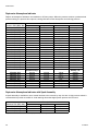
Table 4: Torque Values (*see FIG. 2, page 4)
Assembly Torque ft-lbs (N.m)
MJ MD MSP/MH MX MXP MGO MSD-SST
Tie Rod Nuts 12 (16.3) - 5-8 (6.8-10.9) 23 (31.2) 6-9 (8.1-12.2) 12 (16.3) 5-8 (6.8-10.9)
Indicator Plugs* 6-7
(8.1-9.5)
15 (20.3) 8-9
(10.9-12.2)
18 (24.4) 12-15
(16.3-20.3)
6-8
(8.1-10.9)
5-7 (6.8-9.5)
End Plugs* 11-13
(14.9-17.6)
- 12-15
(16.3-20.3)
46 (62.4) 46-50
(62.4-67.8)
15 (20.34) 6-8 (8.1-10.9)
Valve Section
Mounting Screw
- - 8-9
(10.9-12.2)
- 12-13
(16.3-17.6)
-8-9
(10.9-12.2)

Repair
16 312497P
d. Clean sections and pistons in suitable clean sol-
vent until all lubricant has been removed.
e. Use compressed air to dry and blow out all ports
thoroughly.
A small metal probe should be used to make
sure all passages are clean and open.
Inspect cylinder bore and piston carefully for
scratches, score marks or other damage.
NOTE: If either piston or cylinder bore is damaged, a
new section must be installed. All pistons are selectively
fitted to the bore for proper clearance. Be sure to rein-
stall piston only into the valve section from which it was
removed.
f. If divider valve section and piston both appear
in good condition, reassemble section making
certain piston slides smoothly but snugly in cyl-
inder bore.
g. Repeat cleaning and inspection of each section.
After all sections have been cleaned, blown out,
inspected and found to be in good condition,
reassemble divider valve using notes and
sketches (Step 7) as a reference.
NOTE:
• Always use new gaskets.
• Test operation of divider valve using manual pump.
Contamination Blockage
If dirt, foreign material or any other form of contamina-
tion is found in a divider valve, cleaning that divider
valve will only temporarily solve contamination blockage
problems. The source of the contamination must be
eliminated for satisfactory service.
The system filtering method must be investigated, filter
elements should be inspected and cleaned if necessary.
The reservoir filling method should be reviewed to elimi-
nate any chance of foreign material entering the reser-
voir during filling.
Separation Blockage
If a hard wax or soap-like material is found in the Valve
Section, grease separation is occurring. This means that
the oil is being squeezed from the grease at normal sys-
tem operating pressure and the grease thickener is
being deposited in the divider valve. Cleaning the
divider valve will only temporarily solve the problem.
Consult your lubricant supplier for recommendations on
alternate lubricants and your local Graco/Trabon distrib-
utor to verify compatibility with centralized lubricating
systems.
If all indictor port plugs are removed, master will not
cycle. Blockage is in this divider valve.(F
IG. 12).

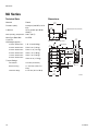
MD Series
312497P 17
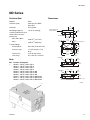
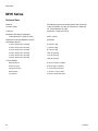
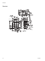
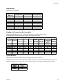
MD Series
Technical Data
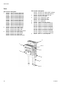
Parts
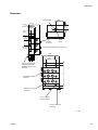
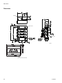
Dimensions
Material Steel
Pressure (max) 3,000 psi (20.7 MPA,
206.8 bar)
Lubricant Oil or grease
Net Weight (approx.) 1-lb. 8 oz (0.68 kg)
Volume (Lubricant to cycle
divider valve one com-
plete cycle)
MD-2, MD-3, MD-4
0.080 in.
3
(1.31 ccm)
MD-6
0.060 in.
3
(0.98 ccm)
Torque Ratings
Assembly Bolts
8-9 ft. lbs (10.9-12.2 N.m)
Enclosure Plugs
11-13 ft. lbs (14.9-17.6
N.m)
Indicator Plug
15 ft. lbs (20.3 N.m)
Outlet Plugs
6-7 ft. lbs. (8.1-9.5 N.m)
Ref Part No. Description
1 562656 VALVE, feeder, MD 2
562657 VALVE, feeder, MD 3
562658 VALVE, feeder, MD 4
562659 VALVE, feeder, MD 6
562653 VALVE, feeder, MD 2, IND
562654 VALVE, feeder, MD 3, IND
562655 VALVE, feeder, MD 4, IND
563270 VALVE, feeder, MD 2, IND/Switch
563271 VALVE, feeder, MD 3, IND/Switch
564356 VALVE, feeder, MD 4, IND/Switch
1
1.19
(30.2
0.87
(22.0)
0.28
(7.11)
1.21
(30.9)
1.19
(30.2
0.87
(22.0)
0.28
(7.11)
1.21
(30.9)
1/8”OUTLET
LUBE INLET
1/8” OUTLET
3.12
(79.3)
3.00
(76.2)
Assembly
Bolts
0.25
(6.3)
1.25
(31.7)
1.75
(44.4)
2.12
(53.9)
0.40
(10.7)
0.28
(7.11) Dia. 2-Mtg. Holes
1.19
(30.2)
0.87
(22.0)
0.28
(7.11)
1.46
(37.0)
OUTLET
,5"%).,%4
v/54,%4-$/NLY
CYCLE INDICATOR
PIN (OPTIONAL)
ti11472

MJ Series
18 312497P
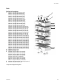
MJ Series
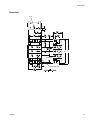
Technical Data Dimensions
Material Plated
Pressure (max) 2,000 psi (13.8 MPa, 137.9
bar)
Lubricant Oil or grease up to NLGI
Grade 1
Max Operating Temperature
200°F (93°C)
Max Cycle Rate With
Cycle Pin
60 CPM
Net Weight (approx.)
3 section divider valve
1-lb. 15 oz (0.88 kg)
4 section divider valve
2 lbs. 5 oz (1.04 kg)
5 section divider valve
2 lbs. 11 oz (1.21 kg)
6 section divider valve
3 lbs. 1 oz (1.38 kg)
7 section divider valve
3 lbs. 7 oz (1.55 kg)
8 section divider valve
3 lbs. 13 oz (1.72 kg)
Torque Ratings
Tie Rod Nut
12 ft. lbs (16.3 N.m)
Enclosure Plug
11-13 ft. lbs (14.9-17.6
N.m)
Outlet Port Plugs
6-7 ft. lbs. (8.1-9.5 N.m)
3.23
(82.2)
1.06
(26.9)
.750
(19.0)
CYCLE INDICATOR PIN (OPTIONAL)
LUBE INLET
INDICATOR OUTLET
.750
(19.0)
1.37
(34.9)
1.09
(27.7)
4 MTG. HOLES
.270 (6.8)
.858
(21.79)
LUBE
OUTLET
B
.250
(6.3)
.582 TYPICAL
(14.7)
2.54
(64.5)
2.12
(53.9)
.687
(17.4)
A
ti11474

MJ Series
312497P 19
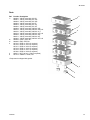
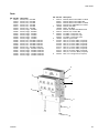
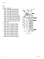
Parts
*Component is shipped with gasket
Ref Part No. Description
1* 562500 VALVE, assembly, MJ 5S
562501 VALVE, assembly, MJ 10S
562502 VALVE, assembly, MJ 15S
562503 VALVE, assembly, MJ 5T
562504 VALVE, assembly, MJ 10T
562505 VALVE, assembly, MJ 15T
562508 VALVE, assembly, IND MJ 10S
562512 VALVE, assembly, IND MJ 10S Left
562510 VALVE, assembly, IND MJ 10 T
562513 VALVE, assembly, IND MJ 10T Left
562509 VALVE, assembly, IND MJ 15S
562511 VALVE, assembly, IND MJ 15T
564205 VALVE, assembly, IND MJ 15T Left
2* 560643 INLET, CRS, MJ
3* 560645 END, CRS, MJ
4 557515 ROD, tie, MJ 3 (3 required)
557516 ROD, tie, MJ 4 (3 required)
557517 ROD, tie, MJ 5 (3 required)
557518 ROD, tie, MJ 6 (3 required)
557519 ROD, tie, MJ 7 (3 required)
557520 ROD, tie, MJ 8 (3 required)
5 556371 NUT, tie rod, 1/4-28 (3 required)
6 557514 GASKET, feeder, MJ
2
1
6
5
4
3

MSP Series
20 312497P
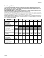
MSP Series
Technical Data
Material Corrosion Protected Steel (optional: Type 303 Stainless
Steel)
Pressure (max)
Zero Leak Inlet
1500 psi (10.3 MPa, 103.4 bar)
Shunt/Shutoff Inlet
3000 psi (20.7 MPa, 206.8 bar)
Ambient Temperature (max) 140°F (60°C)
Lubricant
Zero Leak Inlet
Oil Only - up to 5000 SUS, requires 25 micron (min) fil-
tration
Shunt/Shutoff Inlet
Oil and fluid grease - filter oil through 25 micron filter and
grease through 100 micron mesh strainer
New Weight (approx.)
Carbon Steel
3 section divider valve assembly
5.9 lbs (2.7 kg)
4 section divider valve assembly
7.3 lbs (3.3 kg)
5 section divider valve assembly
8.7 lbs (4.0 kg)
6 section divider valve assembly
10.2 lbs (4.6 kg)
7 section divider valve assembly
11.6 lbs (5.6 kg)
8 section divider valve assembly
13.0 lbs (5.9 kg)
Stainless Steel
3 section divider valve assembly
8.2 lbs (3.7 kg)
4 section divider valve assembly
9.9 lbs (4.5 kg)
5 section divider valve assembly
11.7 lbs (5.3 kg)
6 section divider valve assembly
13.5 lbs (6.2 kg)
7 section divider valve assembly
15.2 lbs (6.9 kg)
8 section divider valve assembly
16.9 lbs (7.7 kg)
Torque Ratings
Mounting Screw
8-9 ft. lbs (10.9-12.2 N.m)
Enclosure Plugs
6-8 ft. lbs (8.1-9.5 N.m)
Indicator Port Plug
5-7 ft. lbs (6.8-9.5 N.m)
Bleed Screws
1-2 ft. lbs. (1.4-2.7 N.m)
Tie Rod Nut
5-8 ft. lbs. (6.8-10.9 N.m)
Page is loading ...
Page is loading ...
Page is loading ...
Page is loading ...
Page is loading ...
Page is loading ...
Page is loading ...
Page is loading ...
Page is loading ...
Page is loading ...
Page is loading ...
Page is loading ...
Page is loading ...
Page is loading ...
Page is loading ...
Page is loading ...
Page is loading ...
Page is loading ...
Page is loading ...
Page is loading ...
Page is loading ...
Page is loading ...
Page is loading ...
Page is loading ...
-
 1
1
-
 2
2
-
 3
3
-
 4
4
-
 5
5
-
 6
6
-
 7
7
-
 8
8
-
 9
9
-
 10
10
-
 11
11
-
 12
12
-
 13
13
-
 14
14
-
 15
15
-
 16
16
-
 17
17
-
 18
18
-
 19
19
-
 20
20
-
 21
21
-
 22
22
-
 23
23
-
 24
24
-
 25
25
-
 26
26
-
 27
27
-
 28
28
-
 29
29
-
 30
30
-
 31
31
-
 32
32
-
 33
33
-
 34
34
-
 35
35
-
 36
36
-
 37
37
-
 38
38
-
 39
39
-
 40
40
-
 41
41
-
 42
42
-
 43
43
-
 44
44


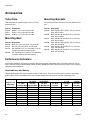
Graco 312497P - Trabon Divider Valves User manual
- Type
- User manual
- This manual is also suitable for
Ask a question and I''ll find the answer in the document
Finding information in a document is now easier with AI
Related papers
-
Graco 312497ZAE - Trabon Divider Valves Operating instructions
-
-
Graco 333113B Inline Filter User manual
-
-
-
-
-
-
-
Other documents
-
sks MSP User manual
-
ABB M2004 User manual
-
BENDIX TCH-001-038 User manual
-
Danfoss Oil Pump BFPW Installation guide
-
Toro Remote Oil Filter Kit, Z Master Installation guide
-
Terex TS14G Maintenance Manual
-
 WÄRTSILÄ WÄRTSILÄ 50DF User manual
-
 Lugger L1066A User manual
-
-
Nothern Lights M175C2 User manual

